EP0031002A1 - Machine rotative avec deux axes non parallèles l'un par rapport à l'autre - Google Patents
Machine rotative avec deux axes non parallèles l'un par rapport à l'autre Download PDFInfo
- Publication number
- EP0031002A1 EP0031002A1 EP80105799A EP80105799A EP0031002A1 EP 0031002 A1 EP0031002 A1 EP 0031002A1 EP 80105799 A EP80105799 A EP 80105799A EP 80105799 A EP80105799 A EP 80105799A EP 0031002 A1 EP0031002 A1 EP 0031002A1
- Authority
- EP
- European Patent Office
- Prior art keywords
- rotor
- working space
- unit according
- rotary unit
- housing
- Prior art date
- Legal status (The legal status is an assumption and is not a legal conclusion. Google has not performed a legal analysis and makes no representation as to the accuracy of the status listed.)
- Granted
Links
Images




Classifications
-
- F—MECHANICAL ENGINEERING; LIGHTING; HEATING; WEAPONS; BLASTING
- F01—MACHINES OR ENGINES IN GENERAL; ENGINE PLANTS IN GENERAL; STEAM ENGINES
- F01C—ROTARY-PISTON OR OSCILLATING-PISTON MACHINES OR ENGINES
- F01C3/00—Rotary-piston machines or engines with non-parallel axes of movement of co-operating members
- F01C3/06—Rotary-piston machines or engines with non-parallel axes of movement of co-operating members the axes being arranged otherwise than at an angle of 90 degrees
Definitions
- the invention relates to a rotary assembly according to the preamble of claim 1.
- the known construction entails that the Inlet and outlet channels of the unit designed as a displacement machine must also be provided in a relatively complicated shape on the housing periphery, which in the case of the conveyance of impure media carrying solids towards the end of compression can also lead to jamming of the solid body between the two end walls of the working area.
- the invention is based on the object for the corresponding genus Rotationsaggre g at a simpler and more particularly from simple parts can be prepared to find existing construction, which also has no outgoing from the working space as possible dead spaces.
- Such trained Rotationsag g re g at only consists of relatively simple construction parts, start from the working space and no dead spaces more.
- the required at a training unit of the rotation as displacement inlet and outlet channels can thereby originate from the housing bottom, reducing the risk of a q uetschungen about entrained debris in the compression end is virtually impossible.
- a structurally particularly simple embodiment of the invention is characterized in claim 2.
- the vanes can be combined with an input shaft that penetrates the housing to form an impeller, and the rotor can be taken from the vanes.
- a further, also advantageous embodiment of the invention is characterized in claim 5, which makes it possible to provide the impeller with four vanes, of which only two diametrically opposed to the transmission of the drive torque are rigidly connected to the drive shaft, while the other two, also diametrically opposite wings can easily yield to the slight operational fluctuations in position compared to the rigid wings.
- a further advantageous embodiment which is particularly advantageous when the rotary unit is used as a vacuum pump, is characterized in claim 16.
- the tapered radial cross-sectional profile towards the floor of the work area makes it possible for a pump provided with an impeller to always position the impeller tightly against the walls of the work area and, in the event of wear on the wings, to automatically adjust to the floor of the work area , so that an optimal sealing of the sash against that of the work area is ensured at all times.
- the radial cross-sectional profile can have, for example, a V-shape or else the shape of a circular section or an arc of a circle which in the middle also forms the bottom.
- the rotary unit is designed to form a double-acting displacement machine, the two stages of which can be connected in series, for example in the interest of increasing the delivery pressure of the machine designed as a compressor.
- Another, also advantageous embodiment of the invention is characterized in claim 20.
- the possibility is created to change the delivery rate of a rotary unit designed as a pump independently of the speed.
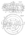
- Fi g . 1 and 2 as a displacement machine designed for different uses, consists of an approximately pot-shaped housing 1, the cover 2 of which is axially penetrated by a drive shaft 3 of an impeller 4 rotatably mounted in the housing 1.
- the housing 1 accommodates the impeller 4 at the top in a free space 5, which is delimited at the bottom by a support surface 6, which runs obliquely for an annular disk-shaped rotor 7 and which is held by a retaining screw 8 about an axis running perpendicular to the support surface 6 9 is rotatable, which includes a pointed Winekl a with the axis of rotation 10 of the impeller 4.
- the bottom part of the Ge formed below the support surface 6 housing 1 is penetrated by an annular working space 11 which is concentric with the axis of rotation 10 and which has a cone-shaped bottom 11a.
- the tip of the cone shell containing the base 11a coincides with the intersection S between the axis 9 and the axis of rotation 10.
- the working space 11 is cylindrical with two side walls 11b and 11c concentric with the axis of rotation 10. From Fig.
- the interruption point 11e in the bottom 11a of the working space 11 is adjoined on both sides by an annular section-shaped inlet and outlet channel 12a or 12b which penetrates downward through the bottom of the housing 1.
- the impeller connected to the drive shaft 3 consists of a circular disk-shaped base body 4a, of which four vanes 13 are distributed uniformly along a concentric circle running above the annular working space 11, each within a radial plane down into the Extend working space 11, each penetrating a radial slot 14 of the rotor 7 corresponding to the wing width.
- the vanes 13 are adapted to the radial cross-sectional profile of the working space 11 so that they rest on the bottom 11a and the side walls 11b and 11c thereof with only a small amount of play, which allows the frictionless rotation of the impeller 4 in the working space 11.
- the mode of operation of the displacement machine according to FIGS. 1 and 2 as a pump is comparable to the mode of operation of a conventional impeller pump.
- the vanes 13 according to FIG. 2 By driving the impeller 4 from the drive shaft 3, the vanes 13 according to FIG. 2, for example, pass over clockwise from the point of interruption 11e the inlet channel 12a and thus each form an increasingly larger suction space in the direction of rotation, into which the liquid to be pumped is sucked in through the inlet channel.
- the liquid to be conveyed is conveyed further into the outlet channel 12b from the pressure space opposite the inlet channel, which becomes smaller in the direction of rotation of the vanes 13.
- the working space 11 can also have a flat floor 11a, in which case, however, the bearing surface 6 must be conically inclined towards the axis 9 of the rotor 7 after the intersection S and in such a way that in the one shown in FIG 3 on the right, the radial plane of the displacement machine, the radial direction of the support surface 6 there also runs within the plane of the base 11a.
- the lower side surface 7d of the rotor 7 facing the bearing surface 6 and forming the second end wall of the working space 11 must also be correspondingly conical.
- this also results in lower end faces for the wings 13 which are located in a common transverse plane to the axis of rotation 10 and which slide along the floor 11a during operation of the displacement machine.
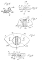
- each slot 14 which consists of two rectangular plates 15a and 15b running parallel to one another, which extend over their two ends at a distance corresponding to the radial wing width from each other arranged approximately semicircularly curved bracket parts 15c in the sense of pressing the facing plate edges against the Side surfaces of the wing 13 passing through the seal 15 are connected to one another in an elastically resilient manner.
- the seals 15 ° can also consist of two approximately semicircular plates 15'a and 15'b, the 'c a along their e common circular periphery m arranged, radially resilient ring 15 against its diametrical gap penetrating wing 1 3 are pressed.
- a suitable recess 7a is then expediently used to accommodate the seal 15 'at the location of each radial slot 14 on the side of the rotor 7 facing the working space 11.
- the inclination of the support surface 6 does not have to be adapted to the radial inclination of the base 11a in the manner shown in FIG. 1, as long as only the flattening of the base 11a provided at the support point of the rotor 7 runs exactly in the plane of the support surface 6. It is then understandably no longer a question of a particular conical shape of the base 11a, which, apart from the point of interruption 11e, can then also be flat.
- the impeller 4 need only have two diametrically opposed vanes 13, which are then rigidly connected to the drive shaft 3. Although four blades 13 provide a slightly larger and virtually pulse-free F örder- stream, but can not follow during their rotation the slots 14 of the rotor 7 closely. If the acute angle ⁇ between the axis 9 of the rotor 7 and the axis of rotation 10 of the drive shaft 3 is not chosen to be very small, which of course also leads to a correspondingly low delivery capacity of the unit, it is advantageous if, in addition to the seals 15 and 15 ' also special measures are taken on the impeller 4, which can avoid a larger game at the location of the slots 14. In the embodiment shown in FIG.
- the impeller 4 is provided with two diametrically opposed vanes 13a for this purpose, which are rigidly connected to the drive shaft 3 via spokes 13'a, while another two, also diametrically opposed Overlying vanes 13b are connected to the drive shaft 3 via a thinner, elastically resilient spoke 13'b each with the drive shaft 3.
- the drive transmission to the rotor 7 then takes place essentially via the vanes 13a, while the vanes 13b cause the movements of the associated slots 14 from the cross shape of the vane wheel 4 shown in FIG can yield in the manner shown in FIG. 4 in a greatly exaggerated dashed line.
- the size of the acute angle a shown in FIG. 1 and the corresponding inclination of the rotor 7 there is only a deflection of only about 1 °.
- the rotor 7 is in front of each radial slot 14a in the direction of rotation of the rotor 7 indicated by an arrow 16 in FIG. 11
- the side facing the support surface 6 is provided with a respective working space with a groove 17 or 17a which leads radially inwards and is indicated by dashed lines in FIG. 11, the groove 17 extending beyond the circle having the outlet duct 12b and the groove 17a extending beyond the circle having the outlet duct 12 'b receiving circle in the bottom of the housing 1 protrudes.
- FIGS. 12 and 13 again show a displacement machine which is intended in particular for the compression of gases. It differs from the displacement machine according to the first embodiment mainly in that the vanes 13 in plan view an approximately trapezoidal cross section with a ents p recnend large sealing surface opposed to the bottom 11a of the working space 11 have and the working space 11 is tapered in a radial cross-section towards its bottom 11a. Accordingly, the aforementioned flüael 13 are tapered V-shaped towards their free ends. Such or similar tapering of the working space 11 and the vanes 13 makes it possible in a simple manner to compensate for unavoidable wear and tear at the sealing contact points of the vanes 13 by a simple axial adjustment of the impeller 4 after the working space 11.
- This readjustment can be carried out, for example, by a helical spring 19 surrounding the drive shaft 3 and supported on the one hand on the base body 4a of the impeller 4 and on the other hand on the cover 2 of the housing 1.
- a helical spring 19 surrounding the drive shaft 3 and supported on the one hand on the base body 4a of the impeller 4 and on the other hand on the cover 2 of the housing 1.
- the helical spring 19 shown in FIG. 12 can also be dispensed with if the space of the housing 1 located above the rotor 7 is acted upon by the pressurized conveying medium, for example from the pressurized outlet channel 12b. Since this results in a pressure component on the impeller after the working space 11, an automatic readjustment of the impeller 4 also takes place in this way.
- the cover 2 extends with a cylindrical projection 2a to the support surface 6 of the housing 1 and receives the outer edge of the rotor 7 in an annular groove 20, which prevents the rotor 7 from lifting off the support surface 6. There is therefore no need for any further axial guidance of the rotor 7, which, for manufacturing reasons, is only centered on an axial pin 1a of the housing 1.
- the disk-shaped rotor 7 is in an annular groove 20 along its outer circumference which is coherent in a ring of the housing 1 and axially centered on a ball 21 which is mounted in a ball socket 22 arranged axially to the impeller 4 in the bottom of the housing 1.
- the impeller 4 has only two diametrically opposite vanes 13, which start from a circular disk-shaped base body 4a of the impeller 4.
- the end face 4b of the base body 4a facing the rotor 7 has the shape of a cone which is a mirror image of the conical surface of the bottom 11a of the working space 11, and the impeller 4 is arranged axially so that the rotor 7 does the same according to FIG. 14 along one in this FIG touches the surface line on the left.
- the inlet and outlet ducts 12a and 12b designed for the lower working space 11 in the manner described so far are indicated by dashed lines in FIG.
- the similar displacement machine corresponding to the next exemplary embodiment shown in FIGS. 16 and 17 is likewise designed to be double-acting, an annular disk-shaped rotor 7 being both axially guided and radially centered in an annular groove 20.
- the vanes 13 do not extend axially but radially from the base body 4a of the impeller 4, connecting to the disk-shaped base body 4a in each case via a short connecting rod 23 projecting radially outwards.
- the disc-shaped base body extending 4a according to Fi g. 16 at the same time within the central transverse plane of the wings 13, within which the centers of gravity S 'of the wings 13 are thus also located.
- the wings 13 are thus securely held on the base body 4a even at high speeds and correspondingly large centrifugal forces without the risk of tilting moments occurring on them.
- the advantageous embodiment has the advantage that the inlet and outlet ducts 12'a and 12'b assigned to the upper annular working space 11 "and indicated by dash-dotted lines in FIG. 17 can now be provided in a simple shape in the cover 2 of the housing 1. Also 3, of course, is connected to corresponding inlet and outlet ducts, which are mirror images of the vertical plane there according to FIG. 3 and which are located in the bottom of the housing 1. Otherwise, the shape of the inlet and outlet ducts 12 'shown results from a and 12'b that this displacement machine works as a compressor.
- the construction shown entails that the plane of the base body 4a also accommodates the intersection S between the axis 9 of the rotor 7 and the axis of rotation 10 of the drive shaft 3.
- FIG. 18 shows a further embodiment of a single-acting displacement machine which has a working space 11 in its housing 1 with a radial cross-sectional profile in the form of a ring section.
- the vanes 13 of the impeller 4 immersed in the working space 11 also have an annular section-shaped profile in the plane shown, the center of both ring sections simultaneously being the center of an upwardly projecting spherical head 24 located at the lower tip of the conical bottom 11a of the working area 11 of the housing 1, on which the rotor 7 is mounted by means of an axial lower ball socket 25.
- the rotor 7 In its outer circumferential area located above the working space 11, the rotor 7 has a ring 7 'which plunges downward into the working space 11 and which, with an adapted ring-shaped radial cross-sectional profile in the working space 11, depending on the angular position of the adjustable in a manner not shown Immerse Rotors 7 more or less deeply.
- this rotor 7 also has a ralial slot 14 at the location of each wing 13, through which the wing 13 plunges into the working space 11 as far as the bottom 11a thereof.
- the rotor 7 If the rotor 7 is not pressed against the ball head 24 by an above-mentioned upper pressurization, it could also be pressed against the ball head 24 by a compression spring 26 arranged axially to the base body 4a of the impeller 4 between the latter.
- a compression spring 26 arranged axially to the base body 4a of the impeller 4 between the latter.
- the rotary drive takes place via the disk-shaped rotor 7, which in turn is non-rotatably connected to the drive shaft 18.
- the two working spaces 11 and 11 "located here together form an annular space which is rectangular in radial cross section, the central plane 11d of which is inclined with respect to the central plane 7b of the rotor 7 running transverse to the drive shaft 18, the central axis 10 'of this annular space defining the axis 9 of the drive shaft 18 on the Center plane 7b intersects and forms an angle a with axis 9.
- the wings 13 Since the wings 13 perform slight back and forth tilting movements with respect to the two floors 11a and 11 "a cer both working spaces 11 and 11" due to the mutual inclination of the two central planes 7b and 11d, they also have rounded end faces 13d towards these floors whose axes of curvature lie on the center lines of the wings 13, which are simultaneously taken up by the central plane 11d and radially to the center lines running through the two working spaces 11 and 11 ".
- inlet and outlet channels are also provided in the bottom 11a and 11 "a, of which the ones in the bottom 11a (12a and 12b) are indicated by dashed lines in FIG. 20.
- the displacement machine according to Fig. 20 six wings 13 on.
- the mutually independent vanes 13 always find the most uniform possible external support against the occurring, correspondingly high centrifugal forces even at high speeds of the rotor 7, have in the exemplary embodiment shown in FIG. 21, modified compared to FIGS. 19 and 20 and kept only schematically the two working spaces 11 and 11 "combined to form a ring channel in the axial section of the rotor 7 have the shape of a ring section and also the radially outer edges 14 'of the slits 14 forming the closed recesses. are adapted in shape and position to the corresponding circular arc shape of the outer side walls 11b and 11 "b of the working spaces 11, 11 ".
- the wings 13 now also have the same ring-section-shaped profile, as can be seen from FIG. 21.
- the shaft 3 which penetrates the cover 2 outwards is guided there by means of an outer collar 3a in a driving fork 28 which penetrates the tube extension 27 in diametrically opposite slots 27a and which, in a conventional manner (not particularly illustrated), from the outside opposite the wing 13 into the working space 11 prestressing coil spring 19 can be moved axially to the tube extension 27 (according to FIG. 22) upwards.
- the two vanes 13 are also increasingly pulled out of the working space 11, which leads to a correspondingly increasing slip between the operationally rotating rotor 7 and the housing 1 entrained therefrom via the vanes 13.
- the sealing of the vanes in the slots of the rotor can be simplified in that the rotor consists of two, approximately semicircular disks that leave the slot spaces between them, the outside and / or in the place of an inner hub are held together by a spring ring which compresses the two parts in an elastically resilient manner, through which a sealing engagement of the two parts of the rotor 7 on the vanes 13 is then brought about at the same time.
- Special seals 15, such as those shown in FIGS. 5 to 9 can then be dispensed with. If a pump modified in this way, which otherwise corresponds to the exemplary embodiment shown in FIGS.
- annular working channel which, instead of a radial V cross section, has an approximately semicircular cross section, then such a pump is particularly suitable for conveying liquids with abrasive solids, for example also for pumping liquid concrete.
- the V in FIGS. 16 and 17 as well as 19 and 20 shown ER- closer may also be modified such that the one, for example, upper annular working chamber 11 is "11 downstream of the other working chamber in the gas stream as a second compressor stage and according to the now smaller volume the compressed G a-ses having a smaller radial width than the working space 11. of course, the profile of the upper portions of the blades 13 is then adjusted accordingly.
- the leading from the main body 4a to the wings 13 connecting rods 23 may in particular if, instead of the two illustrated opposite wings 13 are distributed along the circumference of the annular working spaces even more wings can be rotated about their radial axes or be elastically deformable so that the wings can better adapt to the changing displacements caused by the rotor 7.
- the latter could also consist of two or three identical disks lying one on top of the other, which can then experience minor displacements relative to one another during operation.
- the centrifugal forces which occur radially on the vanes 13 could also be absorbed by a cylindrical ring which surrounds all vanes and which can then also be used as a component of an external electric drive.
- the base body 4a and the drive shaft 3 can then be dispensed with and the vanes 13, according to the exemplary embodiments shown in FIGS. 19 to 21, can be arranged without an internal mutual cohesion.
- the wings 13 there could also be held via radial spokes on a ring surrounding the drive shaft 18, via which the centrifugal forces which occur on the wings 13 are then absorbed.
- the radial cross-sectional profile of the work space 11 could also be designed differently than in the illustrated embodiments, as long as it is ensured that the wings 13 completely fill this profile with their corresponding profile.
- the rotary unit could also have more annular work spaces arranged concentrically to one another in the radial direction, it being advantageous that this does not result in a larger number of parts which are movable relative to one another.
- a coolant can flow through the interior space of the housing remaining above the rotor in order to dissipate the heat which arises in particular in the case of high-speed units or when hot media are conveyed.
- a displacement machine according to the invention can also be used as an exhaust gas or displacement turbine, which is even suitable for the highest pressures.
- the described function of a hydrostatic clutch can also be used for use as a hydraulic transmission.
- a better sealing of the annular working space with respect to the space located above the rotor can also be achieved by arranging an annular seal along circles on both sides of the working space between the contact surface for the rotor and the rotor itself.
- the displacement machine can thus also be used advantageously as a volume meter, vacuum pump and compressed air motor at high speeds and also in oil-free operation.
- the thermal R-o bustheit can at a suitable cooling also provides a use for pumping hot media, such as liquid metals, or as a combustion engine (Verdrängerturbine) to. It can also be operated as an internal combustion engine with a work process similar to the known Stirling engines and two displacement machines, each designed as a turbine and compressor, can be coupled to one another to form a common unit.
- the same can, for example, be more or less immersed in an oil bath within a transmission housing, which may also act on the side of the rotor remote from the annular working space.
- the fact that the blades pass over the front end of the inlet channel in the direction of rotation each time in the manner of a knife can ultimately also be used to use the rotary aggregate, which is otherwise designed as a pump, as a comminution machine, for example for chopping straw.
Landscapes
- Engineering & Computer Science (AREA)
- Mechanical Engineering (AREA)
- General Engineering & Computer Science (AREA)
- Rotary Pumps (AREA)
- Treatment Of Fiber Materials (AREA)
- Preliminary Treatment Of Fibers (AREA)
- Press Drives And Press Lines (AREA)
- Reciprocating Pumps (AREA)
- Structures Of Non-Positive Displacement Pumps (AREA)
Priority Applications (1)
| Application Number | Priority Date | Filing Date | Title |
|---|---|---|---|
| AT80105799T ATE24346T1 (de) | 1979-11-16 | 1980-09-25 | Winkelachsige rotationskolbenmaschine. |
Applications Claiming Priority (2)
| Application Number | Priority Date | Filing Date | Title |
|---|---|---|---|
| DE2946304A DE2946304C2 (de) | 1979-11-16 | 1979-11-16 | Drehkolbenartige Rotationskolbenmaschine |
| DE2946304 | 1979-11-16 |
Publications (2)
| Publication Number | Publication Date |
|---|---|
| EP0031002A1 true EP0031002A1 (fr) | 1981-07-01 |
| EP0031002B1 EP0031002B1 (fr) | 1986-12-17 |
Family
ID=6086163
Family Applications (1)
| Application Number | Title | Priority Date | Filing Date |
|---|---|---|---|
| EP80105799A Expired EP0031002B1 (fr) | 1979-11-16 | 1980-09-25 | Machine rotative avec deux axes non parallèles l'un par rapport à l'autre |
Country Status (4)
| Country | Link |
|---|---|
| US (1) | US4548559A (fr) |
| EP (1) | EP0031002B1 (fr) |
| AT (1) | ATE24346T1 (fr) |
| DE (2) | DE2946304C2 (fr) |
Families Citing this family (3)
| Publication number | Priority date | Publication date | Assignee | Title |
|---|---|---|---|---|
| US4884957A (en) * | 1986-07-11 | 1989-12-05 | Wolfhart Wilimczik | Displacement machine having displacement body and sealing members rotating on non-parallel axes |
| US8834140B2 (en) | 2004-05-25 | 2014-09-16 | Cor Pumps + Compressors Ag | Leakage loss flow control and associated media flow delivery assembly |
| DE102004026048A1 (de) * | 2004-05-25 | 2005-12-29 | Cor Pumps + Compressors Ag | Spaltverluststromsteuerung |
Citations (11)
| Publication number | Priority date | Publication date | Assignee | Title |
|---|---|---|---|---|
| US2242058A (en) * | 1937-11-05 | 1941-05-13 | Ernest A Cuny | Rotary fluid displacement device |
| DE826331C (de) * | 1950-04-22 | 1951-12-27 | Rudolf Bock | Geblaese, bestehend aus zwei in einem Gehaeuse angeordneten, aufeinander abrollenden Drehkoerpern und radialen Scheidewaenden |
| US2828695A (en) * | 1954-02-04 | 1958-04-01 | Marshall John Wilmott | Rotary machine |
| US3034445A (en) * | 1958-01-14 | 1962-05-15 | Standard Res Consultants Inc | Pump |
| GB967636A (en) * | 1960-03-11 | 1964-08-26 | Pietro Mongitore | Rotary fluid engines and pumps |
| FR1503746A (fr) * | 1966-10-12 | 1967-12-01 | Pompe double corps à palettes | |
| US3487787A (en) * | 1967-12-06 | 1970-01-06 | Thompson Wendell L | Vane type rotary fluid displacement device |
| DE1553106A1 (de) * | 1966-04-25 | 1970-07-16 | Lusztig Dipl Ing Gavril | Drehkolbenpumpe |
| US3528242A (en) * | 1968-03-21 | 1970-09-15 | Michael D Hartmann | Rotary positive displacement machines |
| DE1628123A1 (de) * | 1967-10-23 | 1971-09-16 | Rudolf Jacob | Zweikreis-Hydrostatmotor |
| GB1423673A (en) * | 1973-11-19 | 1976-02-04 | Simpson J N | Rotary fluid pump |
Family Cites Families (7)
| Publication number | Priority date | Publication date | Assignee | Title |
|---|---|---|---|---|
| US173030A (en) * | 1876-02-01 | Improvement in rotary engines and water-wheels | ||
| US167146A (en) * | 1875-08-24 | Improvement in disk steam-engines | ||
| US764551A (en) * | 1904-05-13 | 1904-07-12 | William Hero Bot Jr | Rotary engine. |
| GB267509A (en) * | 1926-03-11 | 1928-04-19 | Farid Riz Camel | Improvements in rotary pumps |
| US2101051A (en) * | 1935-07-20 | 1937-12-07 | Cunward Inc | Rotary fluid displacement device |
| US2232599A (en) * | 1939-09-16 | 1941-02-18 | Frank P Fehn | Rotary fluid power device |
| US3622255A (en) * | 1969-08-07 | 1971-11-23 | Gavril T Lusztig | Pump |
-
1979
- 1979-11-16 DE DE2946304A patent/DE2946304C2/de not_active Expired
-
1980
- 1980-09-25 EP EP80105799A patent/EP0031002B1/fr not_active Expired
- 1980-09-25 AT AT80105799T patent/ATE24346T1/de not_active IP Right Cessation
- 1980-09-25 DE DE8080105799T patent/DE3071865D1/de not_active Expired
-
1984
- 1984-09-12 US US06/650,302 patent/US4548559A/en not_active Expired - Fee Related
Patent Citations (11)
| Publication number | Priority date | Publication date | Assignee | Title |
|---|---|---|---|---|
| US2242058A (en) * | 1937-11-05 | 1941-05-13 | Ernest A Cuny | Rotary fluid displacement device |
| DE826331C (de) * | 1950-04-22 | 1951-12-27 | Rudolf Bock | Geblaese, bestehend aus zwei in einem Gehaeuse angeordneten, aufeinander abrollenden Drehkoerpern und radialen Scheidewaenden |
| US2828695A (en) * | 1954-02-04 | 1958-04-01 | Marshall John Wilmott | Rotary machine |
| US3034445A (en) * | 1958-01-14 | 1962-05-15 | Standard Res Consultants Inc | Pump |
| GB967636A (en) * | 1960-03-11 | 1964-08-26 | Pietro Mongitore | Rotary fluid engines and pumps |
| DE1553106A1 (de) * | 1966-04-25 | 1970-07-16 | Lusztig Dipl Ing Gavril | Drehkolbenpumpe |
| FR1503746A (fr) * | 1966-10-12 | 1967-12-01 | Pompe double corps à palettes | |
| DE1628123A1 (de) * | 1967-10-23 | 1971-09-16 | Rudolf Jacob | Zweikreis-Hydrostatmotor |
| US3487787A (en) * | 1967-12-06 | 1970-01-06 | Thompson Wendell L | Vane type rotary fluid displacement device |
| US3528242A (en) * | 1968-03-21 | 1970-09-15 | Michael D Hartmann | Rotary positive displacement machines |
| GB1423673A (en) * | 1973-11-19 | 1976-02-04 | Simpson J N | Rotary fluid pump |
Also Published As
| Publication number | Publication date |
|---|---|
| US4548559A (en) | 1985-10-22 |
| DE2946304C2 (de) | 1983-02-03 |
| DE3071865D1 (en) | 1987-01-29 |
| ATE24346T1 (de) | 1987-01-15 |
| DE2946304A1 (de) | 1981-05-21 |
| EP0031002B1 (fr) | 1986-12-17 |
Similar Documents
| Publication | Publication Date | Title |
|---|---|---|
| DE3506375C2 (de) | Spiralkompressor | |
| EP2137378B1 (fr) | Pompe ou moteur | |
| DE1936492A1 (de) | Rotationsmaschine | |
| DE3519244A1 (de) | Hydraulische maschine der spiralart | |
| DE19509913A1 (de) | Umlaufkolbenmaschine | |
| EP0063240B1 (fr) | Machine à pistons rotatifs | |
| EP1527256B1 (fr) | Machine a piston rotatif avec enveloppe interne mobile | |
| WO1991019088A1 (fr) | Moteur a combustion interne a pistons rotatifs | |
| DE4011671C2 (de) | Regelbare Flügelzellenpumpe | |
| CH675896A5 (fr) | ||
| EP0031002A1 (fr) | Machine rotative avec deux axes non parallèles l'un par rapport à l'autre | |
| DE3146782A1 (de) | Rotationskolbenmaschine | |
| DE2850371A1 (de) | Fluegelzellenkompressor | |
| DE69325368T2 (de) | Regelbare verdrängerpumpe | |
| DE3242983A1 (de) | Regelbare fluegelzellenpumpe | |
| EP4217610B1 (fr) | Groupe moteur-pompe | |
| DE1043230B (de) | Hydraulische Maschine | |
| DE2533776A1 (de) | Drehmotor | |
| EP0474001B1 (fr) | Pompe à engrenages internes pour fluide hydraulique | |
| DE9207087U1 (de) | Rotationskolbenmaschine | |
| DE2555595C2 (de) | Flügelzellenpumpe | |
| EP0473025A1 (fr) | Pompe à engrenages internes pour fluide hydraulique | |
| DE102007039157B4 (de) | Flügelzellenpumpe | |
| DE3603327A1 (de) | Impulswerkzeug mit abschalteinrichtung | |
| DE290349C (fr) |
Legal Events
| Date | Code | Title | Description |
|---|---|---|---|
| PUAI | Public reference made under article 153(3) epc to a published international application that has entered the european phase |
Free format text: ORIGINAL CODE: 0009012 |
|
| AK | Designated contracting states |
Designated state(s): AT CH DE FR GB IT NL SE |
|
| RBV | Designated contracting states (corrected) |
Designated state(s): AT CH DE FR GB IT LI NL SE |
|
| 17P | Request for examination filed |
Effective date: 19811119 |
|
| RAP1 | Party data changed (applicant data changed or rights of an application transferred) |
Owner name: WILLIMCZIK, WOLFHART, DIPL.-PHYS. |
|
| ITF | It: translation for a ep patent filed | ||
| GRAA | (expected) grant |
Free format text: ORIGINAL CODE: 0009210 |
|
| AK | Designated contracting states |
Kind code of ref document: B1 Designated state(s): AT CH DE FR GB IT LI NL SE |
|
| REF | Corresponds to: |
Ref document number: 24346 Country of ref document: AT Date of ref document: 19870115 Kind code of ref document: T |
|
| REF | Corresponds to: |
Ref document number: 3071865 Country of ref document: DE Date of ref document: 19870129 |
|
| ET | Fr: translation filed | ||
| PLBE | No opposition filed within time limit |
Free format text: ORIGINAL CODE: 0009261 |
|
| STAA | Information on the status of an ep patent application or granted ep patent |
Free format text: STATUS: NO OPPOSITION FILED WITHIN TIME LIMIT |
|
| 26N | No opposition filed | ||
| PG25 | Lapsed in a contracting state [announced via postgrant information from national office to epo] |
Ref country code: NL Effective date: 19880401 |
|
| NLV4 | Nl: lapsed or anulled due to non-payment of the annual fee | ||
| PG25 | Lapsed in a contracting state [announced via postgrant information from national office to epo] |
Ref country code: GB Effective date: 19880925 Ref country code: AT Effective date: 19880925 |
|
| PG25 | Lapsed in a contracting state [announced via postgrant information from national office to epo] |
Ref country code: SE Effective date: 19880926 |
|
| PG25 | Lapsed in a contracting state [announced via postgrant information from national office to epo] |
Ref country code: LI Effective date: 19880930 Ref country code: CH Effective date: 19880930 |
|
| PG25 | Lapsed in a contracting state [announced via postgrant information from national office to epo] |
Ref country code: FR Free format text: LAPSE BECAUSE OF NON-PAYMENT OF DUE FEES Effective date: 19890531 |
|
| REG | Reference to a national code |
Ref country code: CH Ref legal event code: PL |
|
| GBPC | Gb: european patent ceased through non-payment of renewal fee | ||
| REG | Reference to a national code |
Ref country code: FR Ref legal event code: ST |
|
| PGFP | Annual fee paid to national office [announced via postgrant information from national office to epo] |
Ref country code: DE Payment date: 19891103 Year of fee payment: 10 |
|
| PG25 | Lapsed in a contracting state [announced via postgrant information from national office to epo] |
Ref country code: DE Effective date: 19910702 |
|
| EUG | Se: european patent has lapsed |
Ref document number: 80105799.3 Effective date: 19890614 |