EP0031002B1 - Machine rotative avec deux axes non parallèles l'un par rapport à l'autre - Google Patents
Machine rotative avec deux axes non parallèles l'un par rapport à l'autre Download PDFInfo
- Publication number
- EP0031002B1 EP0031002B1 EP80105799A EP80105799A EP0031002B1 EP 0031002 B1 EP0031002 B1 EP 0031002B1 EP 80105799 A EP80105799 A EP 80105799A EP 80105799 A EP80105799 A EP 80105799A EP 0031002 B1 EP0031002 B1 EP 0031002B1
- Authority
- EP
- European Patent Office
- Prior art keywords
- disc rotor
- rotor
- housing
- working space
- groove
- Prior art date
- Legal status (The legal status is an assumption and is not a legal conclusion. Google has not performed a legal analysis and makes no representation as to the accuracy of the status listed.)
- Expired
Links
Images




Classifications
-
- F—MECHANICAL ENGINEERING; LIGHTING; HEATING; WEAPONS; BLASTING
- F01—MACHINES OR ENGINES IN GENERAL; ENGINE PLANTS IN GENERAL; STEAM ENGINES
- F01C—ROTARY-PISTON OR OSCILLATING-PISTON MACHINES OR ENGINES
- F01C3/00—Rotary-piston machines or engines with non-parallel axes of movement of co-operating members
- F01C3/06—Rotary-piston machines or engines with non-parallel axes of movement of co-operating members the axes being arranged otherwise than at an angle of 90 degrees
Definitions
- the invention relates to an angular-axis rotary piston machine with an axially vane rotor rotor arranged rotatably in a housing and a disk rotor having radial slots, the axes of rotation of which enclose an acute angle, the vanes reaching through the slots of the disk rotor and on the walls of the working space, from the Disc rotor is covered, run along, the outer diameter of the disc rotor is larger than the outer diameter of the vane rotor. It can be used as a pump, compressor, compressed air or hot gas engine, flow meter, hydrostatic coupling or retarder.
- the object of the invention is to eliminate these disadvantages.
- the aim is to simplify the rotary piston machine mentioned at the beginning and to solve the sealing problem so well that it is not only superior to all other rotary piston machines, but can even compete with the reciprocating piston system in terms of tightness.
- the sealing problem can only be completely solved on one side of the disc rotor, the work area above the disc rotor is initially dispensed with.
- the sealing lines on the disc rotor can be placed from its center plane in its end face, which at the same time forms a contact surface with the groove edges.
- all sealing lines then lie in the plane of contact between the disc rotor and the obliquely cut groove edges.
- the cross-section of the slits is V-shaped in such a way that the narrowest point lies in the plane of contact or surface so that the sealing lines on the groove edge, the wings and the slits converge exactly at one point.
- Angular-axis rotary piston machines with vane rotor and disk rotor with only one-sided working space are known per se from DE-C-8 263 381 and GB-A-967 636.
- the walls of the slots are slightly more inclined than the two axes of rotation to each other.
- the wings also incline in the slots, which is why they are longer than the wings in the radial direction are wide.
- a two-stage displacement machine can easily be implemented without increasing the number of moving parts by accommodating several or two coaxial axial ring grooves in the side of the housing.
- the blades rotate here on different sized concentric circles.
- the advantage here is that the cross-sectional shape, but above all the size of the two work rooms can be made different independently of one another.
- Cylindrical walls can now be used as easy-to-produce walls due to the lack of radial blow holes.
- (Claim 3) On the other hand, a simple automatic adjustment option with even sliding sealing for the wings relative to the walls of the work area is obtained if the cross-section of the annular groove tapers towards the floor, e.g. the lateral walls are conical surfaces or the annular groove is toroidal. If you press the axially displaceable vane rotor against the groove base, for example by an axially working spring (the delivery pressure itself could also generate pressure), the vanes have a very good sealing effect and wear is automatically compensated. (Claim 8) This pressure can, if you want, even during the operation of the machine, be set to the desired level (including zero pressure) and remains independent of the speed and the delivery pressure!
- the bottom of the ring groove can, because its cross-sectional shape is also freely selectable, e.g. be frustoconical. If the oblique angle of this cone coincides with the angle between the two axes of rotation and if the cone tip of the completed cone lies at the intersection of the two axes of rotation in the inclined plane, the surface of the bottom of the annular groove merges with the oblique plane of the housing at a circumferential point, So where the ring groove is interrupted, that is, the fixed separation point between the suction and pressure chamber. In this case there is no dead volume.
- the sloping groove edges can in any case be milled to such an extent that in a more or less long circumferential area (this length is basically also arbitrary) the cross section of the ring groove disappears completely. Since the disc rotor only has a sealing function in the circumferential direction at this circumferential point, where there is no ring groove at all, it is clear that its shape can also be selected independently of the shape of the ring groove.
- the surface of the disc rotor located on the housing wall can e.g.
- the number of wings is basically arbitrary and can be adapted to the respective problem. For good tightness in the slots, however, it must be taken into account that even fixed angles between the vanes in the oblique disc rotor plane constantly change somewhat depending on the angle of rotation. (For an observer in the disk rotor plane, the penetration points of rigid wings through the disk rotor move back and forth somewhat.) To solve this problem, only movable seals or elastic wings have been proposed so far, which makes this machine unsuitable for many applications. The simplest and best solution is of course the one in which these shifts do not occur. This is exactly the case with a wing spacing of 180 °, because this is the only angle (except 0 °) that remains invariant when projected onto an inclined plane, i.e. it does not change. (A straight line remains a straight line for any projection onto another plane). So if you only use two diametrically positioned wings, the problem is completely solved and the seal in the slots is good. (Claim 7)
- This principle has a very high variability and can meet all conditions for the applications already mentioned.
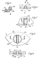
- Figs. 1 and 2 shows e.g. a simple pump.
- the power unit is the vane rotor 4, which is rigidly connected to the shaft 3. It consists of a disk-shaped base body 4a, to which four vanes 13 are rigidly fastened on a concentric circle, which completely fill the cross section of the annular or working space 11.
- the disc rotor 7 has only a sealing function; it lies on the inclined plane 6 with its flat end face 7d and seals the working space 11 towards the open side at least on the pressure or suction side and is carried along by the wings 13 which penetrate it through the radial slots 14.
- the working space is worked into the housing part 1 in the form of an annular groove 11 with cylindrical wall parts 11b, 11c and a cone-shaped groove bottom 11a and is delimited at the top by the inclined plane 6, which is just inclined so that the inclined plane 6 in at a circumferential point 11e the surface of the groove base 11a merges where a linear or areal seal is created between the suction and pressure chamber.
- the axes of rotation and symmetry 9, 10 of the disk rotor 7 and vane rotor 4 intersect at the intersection S in the inclined plane 6 and form an acute angle a.
- the disc rotor 7 is held on the surface 6 by a retaining screw 8. In operation, it is already pressed on the suction side onto surface 6 by the pressure prevailing in space 5, which is sufficient for sealing.
- the slots 14 of the planar disk rotor 7 are cross-sectioned in a V-shape in order to intercept the angle of rotation of the blades 13, which is dependent on the angle of rotation, and to prevent blowholes from being created.
- FIG. 2 shows a plan view of the division of the annular space or the annular groove 11 or the working space.
- the actual conveying area is 13 90 ° long with four blades 13. This is followed on both sides by large-area inlet and outlet channels 12a, b, which extend as far as the separation point 11e.
- FIG. 3 shows the longitudinal section of a pump similar to the first, only that the surface 6 of the housing part 1 is formed by an obliquely lying cone and the end face 7d of the disk rotor 7 is correspondingly conical.
- the bottom 11 of the annular space 11 is flat and touches a surface line of the conical disk rotor 7 at a circumferential point. If one wishes to dispense with elastic slot edges, the other two rigid vanes 13b must be compared with the first rigid diametrical pair of vanes 13a via circumferentially elastic arms 13 Connect 'b to the remaining vane rotor 4 or shaft 3.
- the two wings 13b can then follow the displacements of the slots 14.
- the seal 15 of Fig.5-7 consists of two plates 15a, b, which form the slot edges in a recess of the disc rotor 7 in the slot 14, are elastically connected by two arcuate parts 15c and otherwise have so much play together in the circumferential direction that they can follow the displacements of the slots 14.
- the seal 15 'of Figures 8 and 9 is housed in a circular recess in the disc rotor 7.
- Two half disks 15'a and 15'b are stretched around the wings 13 by a circular wave spring 15'c and at the same time are supported against the wall 7a of the recess.
- 11 e.g. shows a two-stage compressor for oil-free compressed air.
- the disc rotor 7 runs here without contact because it is also supported by a shaft 18 which leads to the outside. (The disc rotor 7, however, requires only a very small drive power to overcome the bearing friction, since it is not a power part).
- the vane rotor 4 consists of the base body 4a, on each of which a diametrical pair of vanes 13b, 13c for an annular space 11 or 11 'is arranged along a diameter.
- Two wings 13 and 13c reach through a common slot 14a.
- the outlet 12b of the first stage lies next to the annular groove and is only connected to the annular groove 11 after a certain internal compression by the groove 17a in the disk rotor 7.
- the gas passes through the inlet 12'a into the inner second stage, the annular or working space 11 'and finally through the control groove 17 to the outlet 12'b in the indicated direction of rotation 16.
- the seal 15 in the slot 14a is not absolutely necessary, since with this arrangement of the wings there are no displacements between the wings and the slots.
- FIG. 12 shows a machine running with contact between the moving parts, for example a compressor.
- the four wings 13 of the wing rotor 4 are tapered by the spring 19 on the shaft 3 into the bottom Ring groove 11 pressed.
- the disc rotor 7 is guided in the radial groove 20.
- the housing part 2 is enlarged by the cylindrical piece 2a, which has been turned out obliquely and receives the oblique groove 20.
- An annularly offset part of the disc rotor 7 also runs in a flat axial annular groove, whereby the flat pin la of the housing part 1 is also formed.
- the slot edges of a slot 14 are not parallel because the cross-section of the wing 13 is not rectangular here, but trapezoidal. The wearing parts automatically adjust themselves here.
- the inlet and outlet channels 12a and 12b lie behind or in front of the fixed separation point between the suction and pressure space, where the cross-section of the annular groove disappears.
Landscapes
- Engineering & Computer Science (AREA)
- Mechanical Engineering (AREA)
- General Engineering & Computer Science (AREA)
- Rotary Pumps (AREA)
- Treatment Of Fiber Materials (AREA)
- Preliminary Treatment Of Fibers (AREA)
- Press Drives And Press Lines (AREA)
- Reciprocating Pumps (AREA)
- Structures Of Non-Positive Displacement Pumps (AREA)
Claims (8)
Priority Applications (1)
| Application Number | Priority Date | Filing Date | Title |
|---|---|---|---|
| AT80105799T ATE24346T1 (de) | 1979-11-16 | 1980-09-25 | Winkelachsige rotationskolbenmaschine. |
Applications Claiming Priority (2)
| Application Number | Priority Date | Filing Date | Title |
|---|---|---|---|
| DE2946304A DE2946304C2 (de) | 1979-11-16 | 1979-11-16 | Drehkolbenartige Rotationskolbenmaschine |
| DE2946304 | 1979-11-16 |
Publications (2)
| Publication Number | Publication Date |
|---|---|
| EP0031002A1 EP0031002A1 (fr) | 1981-07-01 |
| EP0031002B1 true EP0031002B1 (fr) | 1986-12-17 |
Family
ID=6086163
Family Applications (1)
| Application Number | Title | Priority Date | Filing Date |
|---|---|---|---|
| EP80105799A Expired EP0031002B1 (fr) | 1979-11-16 | 1980-09-25 | Machine rotative avec deux axes non parallèles l'un par rapport à l'autre |
Country Status (4)
| Country | Link |
|---|---|
| US (1) | US4548559A (fr) |
| EP (1) | EP0031002B1 (fr) |
| AT (1) | ATE24346T1 (fr) |
| DE (2) | DE2946304C2 (fr) |
Families Citing this family (3)
| Publication number | Priority date | Publication date | Assignee | Title |
|---|---|---|---|---|
| US4884957A (en) * | 1986-07-11 | 1989-12-05 | Wolfhart Wilimczik | Displacement machine having displacement body and sealing members rotating on non-parallel axes |
| US8834140B2 (en) | 2004-05-25 | 2014-09-16 | Cor Pumps + Compressors Ag | Leakage loss flow control and associated media flow delivery assembly |
| DE102004026048A1 (de) * | 2004-05-25 | 2005-12-29 | Cor Pumps + Compressors Ag | Spaltverluststromsteuerung |
Family Cites Families (18)
| Publication number | Priority date | Publication date | Assignee | Title |
|---|---|---|---|---|
| US173030A (en) * | 1876-02-01 | Improvement in rotary engines and water-wheels | ||
| US167146A (en) * | 1875-08-24 | Improvement in disk steam-engines | ||
| US764551A (en) * | 1904-05-13 | 1904-07-12 | William Hero Bot Jr | Rotary engine. |
| GB267509A (en) * | 1926-03-11 | 1928-04-19 | Farid Riz Camel | Improvements in rotary pumps |
| US2101051A (en) * | 1935-07-20 | 1937-12-07 | Cunward Inc | Rotary fluid displacement device |
| US2242058A (en) * | 1937-11-05 | 1941-05-13 | Ernest A Cuny | Rotary fluid displacement device |
| US2232599A (en) * | 1939-09-16 | 1941-02-18 | Frank P Fehn | Rotary fluid power device |
| DE826331C (de) * | 1950-04-22 | 1951-12-27 | Rudolf Bock | Geblaese, bestehend aus zwei in einem Gehaeuse angeordneten, aufeinander abrollenden Drehkoerpern und radialen Scheidewaenden |
| US2828695A (en) * | 1954-02-04 | 1958-04-01 | Marshall John Wilmott | Rotary machine |
| US3034445A (en) * | 1958-01-14 | 1962-05-15 | Standard Res Consultants Inc | Pump |
| GB967636A (en) * | 1960-03-11 | 1964-08-26 | Pietro Mongitore | Rotary fluid engines and pumps |
| DE1553106A1 (de) * | 1966-04-25 | 1970-07-16 | Lusztig Dipl Ing Gavril | Drehkolbenpumpe |
| FR1503746A (fr) * | 1966-10-12 | 1967-12-01 | Pompe double corps à palettes | |
| DE1628123A1 (de) * | 1967-10-23 | 1971-09-16 | Rudolf Jacob | Zweikreis-Hydrostatmotor |
| US3487787A (en) * | 1967-12-06 | 1970-01-06 | Thompson Wendell L | Vane type rotary fluid displacement device |
| US3528242A (en) * | 1968-03-21 | 1970-09-15 | Michael D Hartmann | Rotary positive displacement machines |
| US3622255A (en) * | 1969-08-07 | 1971-11-23 | Gavril T Lusztig | Pump |
| GB1423673A (en) * | 1973-11-19 | 1976-02-04 | Simpson J N | Rotary fluid pump |
-
1979
- 1979-11-16 DE DE2946304A patent/DE2946304C2/de not_active Expired
-
1980
- 1980-09-25 EP EP80105799A patent/EP0031002B1/fr not_active Expired
- 1980-09-25 AT AT80105799T patent/ATE24346T1/de not_active IP Right Cessation
- 1980-09-25 DE DE8080105799T patent/DE3071865D1/de not_active Expired
-
1984
- 1984-09-12 US US06/650,302 patent/US4548559A/en not_active Expired - Fee Related
Also Published As
| Publication number | Publication date |
|---|---|
| US4548559A (en) | 1985-10-22 |
| DE2946304C2 (de) | 1983-02-03 |
| DE3071865D1 (en) | 1987-01-29 |
| ATE24346T1 (de) | 1987-01-15 |
| DE2946304A1 (de) | 1981-05-21 |
| EP0031002A1 (fr) | 1981-07-01 |
Similar Documents
| Publication | Publication Date | Title |
|---|---|---|
| DE3432915C2 (de) | Innenachsige Drehkolbenmaschine | |
| CH656185A5 (de) | Seitenkanalpumpe. | |
| DE19509913A1 (de) | Umlaufkolbenmaschine | |
| DE4017760A1 (de) | Drehkolbenbrennkraftmaschine | |
| DE2835457C2 (fr) | ||
| EP0031002B1 (fr) | Machine rotative avec deux axes non parallèles l'un par rapport à l'autre | |
| CH675896A5 (fr) | ||
| DE1653921B2 (de) | Rotationskolbenpumpe | |
| EP0137421B1 (fr) | Machine à piston rotatif à axe externe | |
| DE3727281C2 (fr) | ||
| DE3519170C2 (fr) | ||
| DE2913608A1 (de) | Verdraengermaschine | |
| EP0024006B1 (fr) | Ventilateur à piston rotatif | |
| DE3634094A1 (de) | Hydraulische oder pneumatische arbeits- und kraftmaschine | |
| DE1803362A1 (de) | Drehkolbenmaschine | |
| EP1118773A2 (fr) | Pompe ou moteur à palettes | |
| DE2448982A1 (de) | Ls pumpe oder motor arbeitende drehkolbenmaschine | |
| WO1997013957A1 (fr) | Moteur a piston rotatif | |
| CH578677A5 (en) | Rotating hydraulic motor with rotor and vanes - has curved vanes able to slide within curved guides within rotor | |
| EP0277114A1 (fr) | Machine a refoulement. | |
| DE1813216A1 (de) | Stroemungsmittel-Rotationspumpe | |
| DE650691C (de) | Pumpe oder Verdichter mit unter ungleichfoermiger Winkelgeschwindigkeit umlaufenden Doppelfluegelkolben | |
| DE3513073A1 (de) | Starrfluegelverdraengermaschine | |
| CH430027A (de) | Rotationskolbenmaschine | |
| DE4428222C1 (de) | Rotationskolbenpumpe (Lamellenpumpe) |
Legal Events
| Date | Code | Title | Description |
|---|---|---|---|
| PUAI | Public reference made under article 153(3) epc to a published international application that has entered the european phase |
Free format text: ORIGINAL CODE: 0009012 |
|
| AK | Designated contracting states |
Designated state(s): AT CH DE FR GB IT NL SE |
|
| RBV | Designated contracting states (corrected) |
Designated state(s): AT CH DE FR GB IT LI NL SE |
|
| 17P | Request for examination filed |
Effective date: 19811119 |
|
| RAP1 | Party data changed (applicant data changed or rights of an application transferred) |
Owner name: WILLIMCZIK, WOLFHART, DIPL.-PHYS. |
|
| ITF | It: translation for a ep patent filed | ||
| GRAA | (expected) grant |
Free format text: ORIGINAL CODE: 0009210 |
|
| AK | Designated contracting states |
Kind code of ref document: B1 Designated state(s): AT CH DE FR GB IT LI NL SE |
|
| REF | Corresponds to: |
Ref document number: 24346 Country of ref document: AT Date of ref document: 19870115 Kind code of ref document: T |
|
| REF | Corresponds to: |
Ref document number: 3071865 Country of ref document: DE Date of ref document: 19870129 |
|
| ET | Fr: translation filed | ||
| PLBE | No opposition filed within time limit |
Free format text: ORIGINAL CODE: 0009261 |
|
| STAA | Information on the status of an ep patent application or granted ep patent |
Free format text: STATUS: NO OPPOSITION FILED WITHIN TIME LIMIT |
|
| 26N | No opposition filed | ||
| PG25 | Lapsed in a contracting state [announced via postgrant information from national office to epo] |
Ref country code: NL Effective date: 19880401 |
|
| NLV4 | Nl: lapsed or anulled due to non-payment of the annual fee | ||
| PG25 | Lapsed in a contracting state [announced via postgrant information from national office to epo] |
Ref country code: GB Effective date: 19880925 Ref country code: AT Effective date: 19880925 |
|
| PG25 | Lapsed in a contracting state [announced via postgrant information from national office to epo] |
Ref country code: SE Effective date: 19880926 |
|
| PG25 | Lapsed in a contracting state [announced via postgrant information from national office to epo] |
Ref country code: LI Effective date: 19880930 Ref country code: CH Effective date: 19880930 |
|
| PG25 | Lapsed in a contracting state [announced via postgrant information from national office to epo] |
Ref country code: FR Free format text: LAPSE BECAUSE OF NON-PAYMENT OF DUE FEES Effective date: 19890531 |
|
| REG | Reference to a national code |
Ref country code: CH Ref legal event code: PL |
|
| GBPC | Gb: european patent ceased through non-payment of renewal fee | ||
| REG | Reference to a national code |
Ref country code: FR Ref legal event code: ST |
|
| PGFP | Annual fee paid to national office [announced via postgrant information from national office to epo] |
Ref country code: DE Payment date: 19891103 Year of fee payment: 10 |
|
| PG25 | Lapsed in a contracting state [announced via postgrant information from national office to epo] |
Ref country code: DE Effective date: 19910702 |
|
| EUG | Se: european patent has lapsed |
Ref document number: 80105799.3 Effective date: 19890614 |