EP0031076A2 - Gurt, insbesondere Bespannungsgurt für Möbel - Google Patents
Gurt, insbesondere Bespannungsgurt für Möbel Download PDFInfo
- Publication number
- EP0031076A2 EP0031076A2 EP80107770A EP80107770A EP0031076A2 EP 0031076 A2 EP0031076 A2 EP 0031076A2 EP 80107770 A EP80107770 A EP 80107770A EP 80107770 A EP80107770 A EP 80107770A EP 0031076 A2 EP0031076 A2 EP 0031076A2
- Authority
- EP
- European Patent Office
- Prior art keywords
- belt according
- band
- belt
- piece
- furniture
- Prior art date
- Legal status (The legal status is an assumption and is not a legal conclusion. Google has not performed a legal analysis and makes no representation as to the accuracy of the status listed.)
- Granted
Links
Images

Classifications
-
- A—HUMAN NECESSITIES
- A47—FURNITURE; DOMESTIC ARTICLES OR APPLIANCES; COFFEE MILLS; SPICE MILLS; SUCTION CLEANERS IN GENERAL
- A47C—CHAIRS; SOFAS; BEDS
- A47C7/00—Parts, details, or accessories of chairs or stools
- A47C7/02—Seat parts
- A47C7/22—Straps or the like for direct user support or for carrying upholstery
-
- A—HUMAN NECESSITIES
- A47—FURNITURE; DOMESTIC ARTICLES OR APPLIANCES; COFFEE MILLS; SPICE MILLS; SUCTION CLEANERS IN GENERAL
- A47C—CHAIRS; SOFAS; BEDS
- A47C23/00—Spring mattresses with rigid frame or forming part of the bedstead, e.g. box springs; Divan bases; Slatted bed bases
- A47C23/12—Spring mattresses with rigid frame or forming part of the bedstead, e.g. box springs; Divan bases; Slatted bed bases using tensioned springs, e.g. flat type
-
- A—HUMAN NECESSITIES
- A47—FURNITURE; DOMESTIC ARTICLES OR APPLIANCES; COFFEE MILLS; SPICE MILLS; SUCTION CLEANERS IN GENERAL
- A47C—CHAIRS; SOFAS; BEDS
- A47C23/00—Spring mattresses with rigid frame or forming part of the bedstead, e.g. box springs; Divan bases; Slatted bed bases
- A47C23/12—Spring mattresses with rigid frame or forming part of the bedstead, e.g. box springs; Divan bases; Slatted bed bases using tensioned springs, e.g. flat type
- A47C23/26—Frames therefor; Connecting the springs to the frame
-
- Y—GENERAL TAGGING OF NEW TECHNOLOGICAL DEVELOPMENTS; GENERAL TAGGING OF CROSS-SECTIONAL TECHNOLOGIES SPANNING OVER SEVERAL SECTIONS OF THE IPC; TECHNICAL SUBJECTS COVERED BY FORMER USPC CROSS-REFERENCE ART COLLECTIONS [XRACs] AND DIGESTS
- Y10—TECHNICAL SUBJECTS COVERED BY FORMER USPC
- Y10T—TECHNICAL SUBJECTS COVERED BY FORMER US CLASSIFICATION
- Y10T428/00—Stock material or miscellaneous articles
- Y10T428/24—Structurally defined web or sheet [e.g., overall dimension, etc.]
- Y10T428/24008—Structurally defined web or sheet [e.g., overall dimension, etc.] including fastener for attaching to external surface
-
- Y—GENERAL TAGGING OF NEW TECHNOLOGICAL DEVELOPMENTS; GENERAL TAGGING OF CROSS-SECTIONAL TECHNOLOGIES SPANNING OVER SEVERAL SECTIONS OF THE IPC; TECHNICAL SUBJECTS COVERED BY FORMER USPC CROSS-REFERENCE ART COLLECTIONS [XRACs] AND DIGESTS
- Y10—TECHNICAL SUBJECTS COVERED BY FORMER USPC
- Y10T—TECHNICAL SUBJECTS COVERED BY FORMER US CLASSIFICATION
- Y10T428/00—Stock material or miscellaneous articles
- Y10T428/24—Structurally defined web or sheet [e.g., overall dimension, etc.]
- Y10T428/24008—Structurally defined web or sheet [e.g., overall dimension, etc.] including fastener for attaching to external surface
- Y10T428/24017—Hook or barb
-
- Y—GENERAL TAGGING OF NEW TECHNOLOGICAL DEVELOPMENTS; GENERAL TAGGING OF CROSS-SECTIONAL TECHNOLOGIES SPANNING OVER SEVERAL SECTIONS OF THE IPC; TECHNICAL SUBJECTS COVERED BY FORMER USPC CROSS-REFERENCE ART COLLECTIONS [XRACs] AND DIGESTS
- Y10—TECHNICAL SUBJECTS COVERED BY FORMER USPC
- Y10T—TECHNICAL SUBJECTS COVERED BY FORMER US CLASSIFICATION
- Y10T428/00—Stock material or miscellaneous articles
- Y10T428/24—Structurally defined web or sheet [e.g., overall dimension, etc.]
- Y10T428/2419—Fold at edge
- Y10T428/24215—Acute or reverse fold of exterior component
-
- Y—GENERAL TAGGING OF NEW TECHNOLOGICAL DEVELOPMENTS; GENERAL TAGGING OF CROSS-SECTIONAL TECHNOLOGIES SPANNING OVER SEVERAL SECTIONS OF THE IPC; TECHNICAL SUBJECTS COVERED BY FORMER USPC CROSS-REFERENCE ART COLLECTIONS [XRACs] AND DIGESTS
- Y10—TECHNICAL SUBJECTS COVERED BY FORMER USPC
- Y10T—TECHNICAL SUBJECTS COVERED BY FORMER US CLASSIFICATION
- Y10T428/00—Stock material or miscellaneous articles
- Y10T428/24—Structurally defined web or sheet [e.g., overall dimension, etc.]
- Y10T428/24273—Structurally defined web or sheet [e.g., overall dimension, etc.] including aperture
- Y10T428/24322—Composite web or sheet
- Y10T428/24331—Composite web or sheet including nonapertured component
-
- Y—GENERAL TAGGING OF NEW TECHNOLOGICAL DEVELOPMENTS; GENERAL TAGGING OF CROSS-SECTIONAL TECHNOLOGIES SPANNING OVER SEVERAL SECTIONS OF THE IPC; TECHNICAL SUBJECTS COVERED BY FORMER USPC CROSS-REFERENCE ART COLLECTIONS [XRACs] AND DIGESTS
- Y10—TECHNICAL SUBJECTS COVERED BY FORMER USPC
- Y10T—TECHNICAL SUBJECTS COVERED BY FORMER US CLASSIFICATION
- Y10T428/00—Stock material or miscellaneous articles
- Y10T428/24—Structurally defined web or sheet [e.g., overall dimension, etc.]
- Y10T428/24273—Structurally defined web or sheet [e.g., overall dimension, etc.] including aperture
- Y10T428/24322—Composite web or sheet
- Y10T428/24331—Composite web or sheet including nonapertured component
- Y10T428/24339—Keyed
-
- Y—GENERAL TAGGING OF NEW TECHNOLOGICAL DEVELOPMENTS; GENERAL TAGGING OF CROSS-SECTIONAL TECHNOLOGIES SPANNING OVER SEVERAL SECTIONS OF THE IPC; TECHNICAL SUBJECTS COVERED BY FORMER USPC CROSS-REFERENCE ART COLLECTIONS [XRACs] AND DIGESTS
- Y10—TECHNICAL SUBJECTS COVERED BY FORMER USPC
- Y10T—TECHNICAL SUBJECTS COVERED BY FORMER US CLASSIFICATION
- Y10T428/00—Stock material or miscellaneous articles
- Y10T428/24—Structurally defined web or sheet [e.g., overall dimension, etc.]
- Y10T428/24273—Structurally defined web or sheet [e.g., overall dimension, etc.] including aperture
- Y10T428/24322—Composite web or sheet
- Y10T428/24331—Composite web or sheet including nonapertured component
- Y10T428/24339—Keyed
- Y10T428/24347—From both sides
-
- Y—GENERAL TAGGING OF NEW TECHNOLOGICAL DEVELOPMENTS; GENERAL TAGGING OF CROSS-SECTIONAL TECHNOLOGIES SPANNING OVER SEVERAL SECTIONS OF THE IPC; TECHNICAL SUBJECTS COVERED BY FORMER USPC CROSS-REFERENCE ART COLLECTIONS [XRACs] AND DIGESTS
- Y10—TECHNICAL SUBJECTS COVERED BY FORMER USPC
- Y10T—TECHNICAL SUBJECTS COVERED BY FORMER US CLASSIFICATION
- Y10T428/00—Stock material or miscellaneous articles
- Y10T428/24—Structurally defined web or sheet [e.g., overall dimension, etc.]
- Y10T428/24479—Structurally defined web or sheet [e.g., overall dimension, etc.] including variation in thickness
- Y10T428/24488—Differential nonuniformity at margin
-
- Y—GENERAL TAGGING OF NEW TECHNOLOGICAL DEVELOPMENTS; GENERAL TAGGING OF CROSS-SECTIONAL TECHNOLOGIES SPANNING OVER SEVERAL SECTIONS OF THE IPC; TECHNICAL SUBJECTS COVERED BY FORMER USPC CROSS-REFERENCE ART COLLECTIONS [XRACs] AND DIGESTS
- Y10—TECHNICAL SUBJECTS COVERED BY FORMER USPC
- Y10T—TECHNICAL SUBJECTS COVERED BY FORMER US CLASSIFICATION
- Y10T428/00—Stock material or miscellaneous articles
- Y10T428/249921—Web or sheet containing structurally defined element or component
- Y10T428/249924—Noninterengaged fiber-containing paper-free web or sheet which is not of specified porosity
- Y10T428/24994—Fiber embedded in or on the surface of a polymeric matrix
- Y10T428/249942—Fibers are aligned substantially parallel
- Y10T428/249946—Glass fiber
Definitions
- the invention relates to a belt, in particular a covering belt for furniture, consisting of a flat piece of tape made of plastic with reinforcing longitudinal threads made of glass fibers embedded therein and arranged parallel and at a distance from one another.
- Straps of this type are generally used as support elements, but in particular for covering seating and reclining furniture, in which they form a spring base for upholstery pads, mattresses, etc., in a parallel, possibly crossing arrangement.
- a significant problem when using such belts is their attachment to the wooden frame struts of the furniture body. In practice, this is done by first fixing an end region of the tape with the top facing downward using staples and then folding the tape over the already defined area and placing staples again. Only with such double stitching, which is complex and complicated, can a connection be made to the frame struts, which can transmit tensile forces in a size which corresponds to at least part of the tensile strength of the belt. However, the connection always remains a weak point with the frequently observed consequence of a detachment or tearing of the belt from the supporting furniture.
- the invention has for its object to provide a belt that is easy to connect to any part supporting it and with a strength of the connection that is not inferior to the tensile strength of the tape.
- the belt is characterized according to the invention is that it is at least at one end provided with an integrally molded connector body made of plastic which encloses the provided with a refolding and in the area of the secured by welding U mfaltung with through perforations tape end sides and penetrated in the area of the perforations.
- the belt according to the invention is directly and easily connectable via its connecting body to any part carrying it, such as the frame struts of a piece of furniture, by means of stapling, nailing or screwing on, wherein the risk of detachment of the connecting body as a result of tearing out of the staples or the connecting means otherwise used is completely avoidable is.
- the connection between the end of the band and the connector body also has a strength that at least withstands all loads in the area of the tensile strength of the band.
- the double layer formed by the folding and secured by the welding also remains in that area of the strip end in which the continuous perforations weaken the load-bearing strip cross-section, a tensile strength which corresponds at least to that of the normal strip.
- the fact that the connector body penetrates through the holes forming the casting channels when it is cast on or sprayed on is at least in the region of
- the tensile strength of the tape provides the strength of the anchoring of the tape end in the connector body, even if, due to the differences between the plastics selected for the tape piece and for the connector body, no fusion of the parts at the contact surfaces takes place during the casting process.
- Such a merging process is not very desirable anyway, because it also causes weakening phenomena in the band piece itself in the area of the transition from the band piece to the connecting body.
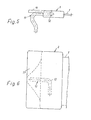
- the belt shown comprises in particular a flat piece of tape 1 made of plastic, in particular polyethylene, with embedded longitudinal reinforcing threads 2 made of glass fibers and a connecting body 3 made of plastic, in particular polypropylene, embedded parallel to one another and spaced apart from one another.
- a particularly strong plastic is preferably chosen for the connection body, since it is then possible Lich is the connection with a frame strut, not shown, of a piece of furniture or any other supporting part with the help of a single suitable staple or the like. Or by one (or more connection hooks).
- the band piece 1 is provided with a fold 4 at its band end.
- This folding 4 is secured by welding to the band piece 1 against leaving its position brought about and illustrated by the folding under load.
- the welding is preferential - performed as the entire surface and illustrated in the drawing in the fifth
- the band end is provided with continuous perforations 6, which form casting channels, which are filled by the material of the connector body 3 when it is poured or sprayed on.
- the perforations are arranged in a row running transversely to the longitudinal direction of the strip and in each case in the region between the longitudinal reinforcing threads 2, so that the longitudinal reinforcing threads remain undamaged.
- the perforations 6 are furthermore arranged close to and along the inner end edge 7 of the fold 4 of the band end, so that it is ensured that the connecting body 3 cannot open in the region of the inlet of the band piece 1 with a corresponding band load.
- the connector body 3 can be provided from its upper and / or its underside down to the adjacent strip surface recesses 8 and 9, which can be arranged in a circle and in a row transversely to the longitudinal direction of the strip.
- the number and size of the recesses depends on the extent of the possible material savings, which in turn depend on the strength of the plastic chosen for the connector body 3.
- Two such recesses are suitable for production technology both on the top and on the underside, because such recesses can be formed in the injection mold by suitable holding and centering members.
- the connector body 3 preferably has the shape of a flat plate rounded at the edges. On its upper side, this can have a shoulder 10 serving as a stop for a stapling or stapling machine (FIGS. 1 to 4).
- connecting body 3 there is considerable scope for modifications in view of specific tasks of the belt. So it is e.g. it is also conceivable to provide the connecting body 3 with an attachment rib which extends at an acute angle to the tape piece and downwards, with the aid of which the connecting body 3 can be fixed to a part provided with a corresponding receiving groove even without tacking or separate connecting means.
- the connector body 3 illustrated in FIGS. 4 and 5 has on its side facing away from the band piece 1 a connector hook 11 which is also injected into the connector body with an angled end 12. If necessary, several connection hooks 11 can also be used.
- the connecting hook 11 enables one Hang in a hole or the like. Cutout in a frame strut.
- the connector body 3 can also be provided with a flange extension 13 which overlaps the connector hook (s) and, as shown, optionally engages in regions on the upper side.
- the flange shoulder 13 can extend over the entire width of the connecting body or, as shown in dashed lines, occupy part of this width.
- the belt is usually provided at both ends with a corresponding connector body 3, especially when used as a clothing belt for furniture, in which the connector body 3 favor a mechanical fixing of the straps on the furniture body.
Landscapes
- Connection Of Plates (AREA)
- Belt Conveyors (AREA)
- Formation And Processing Of Food Products (AREA)
- Devices For Conveying Motion By Means Of Endless Flexible Members (AREA)
- Purses, Travelling Bags, Baskets, Or Suitcases (AREA)
- Buckles (AREA)
Abstract
Description
- Die Erfindung bezieht sich auf einen Gurt, insbesondere Bespannungsgurt für Möbel, bestehend aus einem flachen Bandstück aus Kunststoff mit darin eingebetteten, zueinander im Abstand parallel angeordneten Verstärkungslängsfäden aus Glasfasern.
- Gurte dieser Art finden als Tragelemente allgemein, insbesondere aber für Bespannungen von Sitz- und Liegemöbeln Anwendung, bei denen sie in untereinander paralleler, sich gegebenenfalls kreuzender Anordnung eine Unterfederung für Polsterauflagen, Matratzen etc. bilden. Ein erhebliches Problem bei der Verwendung derartiger Gurte ist deren Festlegung an den Holzrahmenstreben der Möbelkörper. In der Praxis geschieht dies in der Weise, daß zunächst ein Endbereich des Bandes mit nach unten weisender Oberseite durch Heftklammern festgelegt und dann das Band über den schon festgelegten Bereich gefaltet und nochmals Heftklammern gesetzt werden. Nur durch eine solche doppelte Heftung, die aufwendig und kompliziert ist, läßt sich eine Verbindung mit den Rahmenstreben herstellen, die Zugkräfte in einer Größe übertragen kann, die wenigstens einem Teil der Zugfestigkeit des Gurtes entspricht. Jedoch bleibt die Verbindung stets ein Schwachpunkt mit der häufig zu beobachtenden Folgeeines Ablösens bzw. Abreißens des Gurtes vom tragenden Möbel.
- Der Erfindung liegt die Aufgabe zugrunde, einen Gurt zu schaffen, der mit irgendeinem ihn tragenden Teil einfach und mit einer Festigkeit der Verbindung verbindbar ist, die der Zugfestigkeit des Bandes nicht nachsteht.
- Zur Lösung dieser Aufgabe ist der Gurt nach der Erfindung dadurch gekennzeichnet, daß er zumindest an einem Ende mit einem einstückig angegossenen Anschlußkörper aus Kunststoff versehen ist, der das mit einer Umfaltung und im Bereich der durch Verschweißen gesicherten Umfaltung mit durchgehenden Lochungen versehene Bandende allseitig umschließt und im Bereich der Lochungen durchsetzt. Hinsichtlich weiterer Ausgestaltungen wird auf die Unteransprüche 2 bis 9 verwiesen.
- Der Gurt nach der Erfindung ist über seinen Anschlußkörper unmittelbar und einfach an irgendeinem ihn tragenden Teil wie den Rahmenstreben eines Möbels durch Anheften mittels Klammern, Annageln oder Anschrauben verbindbar, wobei Gefahren eines Ablösens des Anschlußkörpers infolge eines Ausreißens der Heftklammern oder der sonst eingesetzten Verbindungsmittel völlig vermeidbar ist. Aber auch die Verbindung zwischen Bandende und Anschlußkörper besitzt eine Festigkeit, die jedenfalls im Bereich der Zugfestigkeit des Bandes allen Belastungen standhält. Die durch die Umfaltung gebildete und durch das Verschweißen gesicherte Doppellagigkeit verbleibt auch in jenem Bereich des Bandendes, in dem die durchgehenden Lochungen eine Schwächung des tragenden Bandquerschnitts herbeiführen, eine Zugfestigkeit, die zumindest der des normalen Bandes entspricht. Dadurch, daß der Anschlußkörper bei seinem Angießen oder Anspritzen am Bandende die Vergußkanäle bildenden Lochungen durchsetzt, ist eine jedenfalls im Bereich der Zugfestigkeit des Bandes liegende Festigkeit der Verankerung des Bandendes im Anschlußkörper gegeben, und zwar auch dann, wenn aufgrund der Unterschiede zwischen den für das Bandstück und für den Anschlußkörper gewählten Kunststoffe beim Angießvorgang kein Verschmelzen der Teile an den Kontaktflächen stattfindet. Ein solcher Verschmelzvorgang ist ohnehin nicht sehr wünschenswert, weil damit zugleich im Bereich des Überganges vom Bandstück zum Anschlußkörper Schwächungserscheinungen im Bandstück selbst eintreten.
- Hinsichtlich weiterer Ausgestaltungen wird auf die Patentansprüche 2 bis 10 verwiesen.
- In der Zeichnung sind zwei Ausführungsbeispiele des Gegenstands der Erfindung näher veranschaulicht. Im einzelnen zeigen:
- Fig. 1 eine Seitenansicht des einen Endbereiches eines Gurtes,
- Fig. 2 eine Draufsicht zu Fig. 1,
- Fig. 3 einen Schnitt nach der Linie III-III in Fig. 2,
- Fig. 4 einen Schnitt nach der Linie IV-IV in Fig.2, und
- Fig. 5 Seitenansicht und Draufsicht ähnlich Fig.1 und 6 und 2 einer abgewandelten Ausführung.
- Der dargestellte Gurt umfaßt im einzelnen ein flaches Bandstück 1 aus Kunststoff, insbesondere Polyäthylen, mit darin eingebetteten, zueinander im Abstand parallel angeordneten Verstärkungslängsfäden 2 aus Glasfasern und einen Anschlußkörper 3 aus Kunststoff, insbesondere Polypropylen. Für den Anschlußkörper wird vorzugsweise ein besonders fester Kunststoff gewählt, da es dann möglich ist, die Verbindung mit einer nicht dargestellten Rahmenstrebe eines Möbels oder irgendeinem sonstigen tragenden Teil mit Hilfe schon einer einzigen geeigneten Heftklammer od. dgl. oder auch durch einen (oder mehrere Anschlußhaken) vorzunehmen.
- Das Bandstück 1 ist an seinem Bandende mit einer Umfaltung 4 versehen. Diese Umfaltung 4 ist durch Verschweißen mit dem Bandstück 1 dagegen gesichert, seine durch die Umfaltung herbeigeführte und dargestellte Lage unter Belastung zu verlassen. Die Verschweißung ist vorzugs- weise vollflächig ausgeführt und in der Zeichnung bei 5 veranschaulicht.
- Im Bereich der Umfaltung 4 ist das Bandende mit durchgehenden Lochungen 6 versehen, die Vergußkanäle bilden, die beim Angießen bzw. Anspritzen des Anschlußkörpers 3 von dessen Material ausgefüllt werden. Bei dem dargestellten Beispiel sind die Lochungen in einer quer zur Bandlängsrichtung verlaufenden Reihe und jeweils im Bereich zwischen Verstärkungslängsfäden 2 angeordnet, so daß die Verstärkungslängsfäden unbeschädigt bleiben.
- Dies ist für die Erhaltung der vollen Zugfestigkeit des Bandstücks 1 und der Verbindung vom Bandstück 1 zum Anschlußkörper 3 wichtig, denn durch die Umfaltung am Bandende erhalten auch die Verstärkungslängsfäden 2 eine solche Umfaltung, die verhindert, daß sich die Verstärkungslängsfäden 2 im Kunststoffmaterial des Bandstücks unter Belastung zurückziehen können. Die Lochungen 6 sind bei dem dargestellten Beispiel ferner nahe und entlang der inneren Endkante 7 der Umfaltung 4 des Bandendes angeordnet, so daß sichergestellt ist, daß der Anschlußkörper 3 nicht im Bereich des Einlaufs des Bandstücks 1 bei entsprechender Bandbelastung aufklaffen kann.
- Zur Einsparung von Material können im Anschlußkörper 3 von dessen Ober- und/oder dessen Unterseite jeweils bis auf die benachbarte Bandfläche herabreichende Ausnehmungen 8 bzw. 9 vorgesehen sein, die kreisförmig und in einer Reihe quer zur Bandlängsrichtung angeordnet werden können. Die Zahl und die Größe der Ausnehmungen hängt vom Umfang der möglichen Materialeinsparungen ab, die ihrerseits von der Festigkeit des für den Anschlußkörper 3 gewählten Kunststoffs abhängig sind. Zwei derartige Ausnehmungen bieten sich sowohl an der Ober- als auch an der Unterseite fertigungstechnisch an, weil derartige Ausnehmungen durch geeignete Halte- und Zentrierglieder in der Spritzgießform gebildet werden können.
- Der Anschlußkörper 3 hat bevorzugt die Form einer an den Kanten abgerundeten flachen Platte. Diese kann an ihrer Oberseite einen als Anschlag für eine Klammersetz- oder Heftmaschine dienenden Absatz 10 aufweisen (Fig.1 bis 4).
- Es versteht sich, daß insbesondere in der Form des Anschlußkörpers 3 ein erheblicher Spielraum für Abänderungen in Ansehung jeweils spezieller Aufgaben des Gurtes besteht. So ist es z.B. auch denkbar, den Anschlußkörper 3 mit einer sich spitzwinklig zum Bandstückfzurück und abwärts vorerstreckenden Befestigungsrippe zu versehen, mit deren Hilfe der Anschlußkörper 3 auch ohne Heft- oder gesonderte Verbindungsmittel an einem mit einer entsprechenden Aufnahmenut versehenen Teil festlegbar ist.
- Der in Fig. 4 und 5 veranschaulichte Anschlußkörper 3 weist auf seiner dem Bandstück 1 abgewandten Seite einen Anschlußhaken 11 auf, der mit einem abgewinkelten Ende 12 in den Anschlußkörper mit eingespritzt ist. Im Bedarfsfalle können auch mehrere Anschlußhaken 11 Anwendung finden. Der Anschlußhaken 11 ermöglicht ein Einhängen in eine Bohrung od.dgl. Aussparung in einer Rahmenstrebe. Der Anschlußkörper 3 kann ferner mit einem Flanschansatz 13 versehen sein, der den oder die Anschlußhaken über- und gegebenenfalls, wie dargestellt, oberseitig bereichsweise umgreift. Der Flanschansatz 13 kann sich über die ganze Breite des Anschlußkörpers erstrecken oder, wie gestrichelt dargestellt ist ein Teil dieser Breite einnehmen.
- Es versteht sich ferner, daß der Gurt in der Regel an beiden Enden mit einem entsprechenden Anschlußkörper 3 versehen ist, insbesondere bei Verwendung als Bespannungsgurt für Möbel, bei der im übrigen die Anschlußkörper 3 ein maschinelles Festlegen der Gurte an den Möbelkörper begünstigen.
Claims (10)
Priority Applications (2)
| Application Number | Priority Date | Filing Date | Title |
|---|---|---|---|
| AT80107770T ATE4083T1 (de) | 1979-12-20 | 1980-12-10 | Gurt, insbesondere bespannungsgurt fuer moebel. |
| DE19813116114 DE3116114A1 (de) | 1980-12-10 | 1981-04-23 | Gurt, insbesondere bespannungsgurt fuer moebel |
Applications Claiming Priority (2)
| Application Number | Priority Date | Filing Date | Title |
|---|---|---|---|
| DE2951329 | 1979-12-20 | ||
| DE2951329A DE2951329C2 (de) | 1979-12-20 | 1979-12-20 | Gurt, insbesondere Bespannungsgurt für Möbel |
Publications (3)
| Publication Number | Publication Date |
|---|---|
| EP0031076A2 true EP0031076A2 (de) | 1981-07-01 |
| EP0031076A3 EP0031076A3 (en) | 1981-09-02 |
| EP0031076B1 EP0031076B1 (de) | 1983-07-13 |
Family
ID=6089030
Family Applications (1)
| Application Number | Title | Priority Date | Filing Date |
|---|---|---|---|
| EP80107770A Expired EP0031076B1 (de) | 1979-12-20 | 1980-12-10 | Gurt, insbesondere Bespannungsgurt für Möbel |
Country Status (5)
| Country | Link |
|---|---|
| US (1) | US4339488A (de) |
| EP (1) | EP0031076B1 (de) |
| JP (1) | JPS5697415A (de) |
| AT (1) | ATE4083T1 (de) |
| DE (1) | DE2951329C2 (de) |
Families Citing this family (37)
| Publication number | Priority date | Publication date | Assignee | Title |
|---|---|---|---|---|
| US4548780A (en) * | 1981-01-27 | 1985-10-22 | Elmwood Sensors Limited | Sensing devices for mounting in chamber walls and a method of manufacture |
| US4517234A (en) * | 1981-05-18 | 1985-05-14 | Amp Incorporated | Heat recoverable sleeve forming wrap |
| US4553786A (en) * | 1983-08-10 | 1985-11-19 | William Lockett, III | Infant seating and lounge unit |
| US4532166A (en) * | 1983-10-03 | 1985-07-30 | Xerox Corporation | Welding of web materials |
| IT1179911B (it) * | 1984-04-16 | 1987-09-16 | Gilardini Spa | Compressore volumetrico per l alimentazione a motori endotermici di veicoli |
| US4703518A (en) * | 1985-08-27 | 1987-10-27 | Minigrip, Inc. | Attachment of plastic zipper to the outside of incompatible bag wall web |
| DE8907459U1 (de) * | 1989-06-19 | 1989-08-03 | Tillner, Alfred, 4513 Belm | Einzugstab zur Profilformung von Polstermaterialien |
| US5419475A (en) * | 1992-03-17 | 1995-05-30 | Taisei Plas Co., Ltd. | Shoulder belt |
| DK0645976T4 (da) | 1992-06-15 | 2003-05-19 | Miller Herman Inc | Kontorstol |
| US5445436A (en) * | 1992-10-15 | 1995-08-29 | Sunbeam Corporation | Backing or seating for seating type furniture and means for securing backing or seating to a frame |
| US5868459A (en) * | 1997-04-10 | 1999-02-09 | Kolcraft Enterprises, Inc. | Bouncer with positive lock |
| US6138327A (en) * | 1999-08-31 | 2000-10-31 | Powell; Andrew P. | Flexible strap arrangement |
| US6983997B2 (en) | 2001-06-29 | 2006-01-10 | Haworth, Inc. | Chair having a suspension seat assembly |
| US6560827B1 (en) * | 2001-08-14 | 2003-05-13 | Gross Jan S | Elastomeric gasket for sling rail furniture |
| US7625046B2 (en) | 2002-03-29 | 2009-12-01 | Garrex Llc | Task chair |
| US7040703B2 (en) | 2002-03-29 | 2006-05-09 | Garrex Llc | Health chair a dynamically balanced task chair |
| US7396082B2 (en) | 2002-03-29 | 2008-07-08 | Garrex Llc | Task chair |
| US20040137811A1 (en) * | 2003-01-09 | 2004-07-15 | L & P Property Management Company | Elastomeric seating composite |
| US20050287347A1 (en) * | 2003-06-02 | 2005-12-29 | Pavilion Furniture, Inc. | Polyurethane and rigid substrate composite with fasteners |
| IL157632A0 (en) * | 2003-08-28 | 2004-03-28 | Keter Plastic Ltd | Furniture item and a method for attaching webbing thereto |
| US7458918B1 (en) | 2003-11-21 | 2008-12-02 | Fitness Quest Inc. | Back support for an exercise device |
| US20050166317A1 (en) * | 2004-02-02 | 2005-08-04 | Kelly Ray G. | Method of manufacture and products using fabric in injection molding |
| AU2005269849B2 (en) | 2004-07-08 | 2009-10-08 | Knoll, Inc. | Office chair |
| EP2787862B1 (de) | 2011-12-08 | 2017-06-07 | Herman Miller, Inc. | Verbundkörper-trägerelement sowie herstellungs- und recyclingverfahren dafür |
| WO2013106864A1 (en) | 2012-01-13 | 2013-07-18 | Ashley Furniture Industries, Inc. | Furniture assembly jig |
| CN103202627B (zh) * | 2012-01-13 | 2018-01-16 | 雅诗立家具工业公司 | 家具组装装配架和对家具产品进行组装的方法 |
| US10105886B2 (en) * | 2012-10-09 | 2018-10-23 | Reliant Worldwide Plastics, Llc | Thermoplastic injection molded element with integral thermoplastic positioning system for reinforced composite structures |
| US20140342106A1 (en) * | 2013-05-15 | 2014-11-20 | Chan-Lin WU | Reinforcing and shape-fixing structure for sheet material product |
| USD703457S1 (en) | 2013-06-07 | 2014-04-29 | Herman Miller, Inc. | Chair |
| US20150014406A1 (en) * | 2013-07-09 | 2015-01-15 | Chan-Lin WU | Reinforcing and shape-fixing strip structure for sheet material product |
| EP3043987A4 (de) | 2013-09-10 | 2017-07-19 | Reliant Worldwide Plastics, LLC | Serviertisch und verfahren zur herstellung |
| WO2015168680A1 (en) | 2014-05-02 | 2015-11-05 | Reliant Worldwide Plastics, Llc | Method and system for homogenous thermoplastic seat back assembly |
| US9623972B2 (en) | 2014-06-16 | 2017-04-18 | Reliant Worldwide Plastics, Llc | Method and apparatus for composite thermoplastic arm rest assembly |
| US10112720B2 (en) | 2015-10-23 | 2018-10-30 | Reliant Worldwide Plastics, Llc | Method and apparatus for a homogeneous thermoplastic leg support |
| US10766174B2 (en) * | 2015-11-04 | 2020-09-08 | Reliant Worldwide Plastics, Llc | Method and apparatus for a thermoplastic homogeneous failure module |
| GB2576727B (en) * | 2018-08-29 | 2022-04-27 | Jaguar Land Rover Ltd | Glazing Assembly and Forming Method |
| CN116461154B (zh) * | 2023-04-13 | 2023-11-03 | 淮安市金福隆包装有限公司 | 一种在瓦楞纸和面纸中间加强力线的装置 |
Family Cites Families (10)
| Publication number | Priority date | Publication date | Assignee | Title |
|---|---|---|---|---|
| DE1113796B (de) * | 1956-10-17 | 1961-09-14 | Peter Hochstrasser | Befestigungseinrichtung fuer elastische Bespannungselemente von Matratzen, Sitzmoebeln od. dgl. |
| GB918743A (en) * | 1960-11-10 | 1963-02-20 | Pirelli Ltd | Improvements in or relating to an upholstery support and a method of making the same |
| GB969573A (en) * | 1962-09-13 | 1964-09-09 | Pirelli Ltd | Improvements in or relating to upholstery support members and the like |
| GB996942A (en) * | 1963-08-23 | 1965-06-30 | Vitafoam Ltd | Improvements in or relating to upholstered furniture |
| US3438099A (en) * | 1967-10-13 | 1969-04-15 | Harold Green | Fastener connections |
| DE6751439U (de) * | 1968-08-22 | 1969-02-13 | Heinrich Kalbskopf Fa | Halterung fuer die polstergurte von polstermoebeln. |
| US3653098A (en) * | 1969-08-19 | 1972-04-04 | Bliss Co | Connector for flat woven tape |
| AU2165570A (en) * | 1970-10-28 | 1972-05-04 | Thyer Rubber Company Pty. Limited | Improvements in and relating to seating |
| US4280548A (en) * | 1977-09-23 | 1981-07-28 | Manfred Brokmann | Furniture such as chairs and couches |
| DE2935787C2 (de) * | 1979-09-05 | 1981-10-15 | Brokmann, Manfred | Rahmenbespannung für Sitz- oder Liegemöbel |
-
1979
- 1979-12-20 DE DE2951329A patent/DE2951329C2/de not_active Expired
-
1980
- 1980-12-10 EP EP80107770A patent/EP0031076B1/de not_active Expired
- 1980-12-10 AT AT80107770T patent/ATE4083T1/de active
- 1980-12-19 JP JP17905580A patent/JPS5697415A/ja active Pending
- 1980-12-22 US US06/218,818 patent/US4339488A/en not_active Expired - Fee Related
Also Published As
| Publication number | Publication date |
|---|---|
| DE2951329A1 (de) | 1981-07-23 |
| ATE4083T1 (de) | 1983-07-15 |
| US4339488A (en) | 1982-07-13 |
| JPS5697415A (en) | 1981-08-06 |
| EP0031076A3 (en) | 1981-09-02 |
| EP0031076B1 (de) | 1983-07-13 |
| DE2951329C2 (de) | 1982-11-11 |
Similar Documents
| Publication | Publication Date | Title |
|---|---|---|
| EP0031076B1 (de) | Gurt, insbesondere Bespannungsgurt für Möbel | |
| DE2437809C3 (de) | Siebboden sowie Siebkörper und Rahmen hierfür | |
| DE69004276T2 (de) | Vorrichtung zum Anhaken von Kofferbändern. | |
| DE2923714A1 (de) | Haltenetz | |
| DE2402644B2 (de) | Einteilige Sitzschale | |
| DE102004053133A1 (de) | Überzug zur Verkleidung von Kraftfahrzeug-Innenräumen und Formteil mit einem solchen Überzug | |
| DE69407395T2 (de) | Verbindungsvorrichtung für fördergurte und befestigungsverfahren dieser vorrichtung an enden von fördergurten | |
| DE1937746A1 (de) | Reissverschluss mit Kunststoffgliedern | |
| DE4219891A1 (de) | Sitz, insbesondere Kraftfahrzeugsitz | |
| DE9017808U1 (de) | Reißverschluß mit textilen Tragbändern und angespritzten Verschlußgliedern | |
| DE2703147C2 (de) | Verfahren zum Verbinden zweier Bandenden und dieses Verfahren anwendendes Band | |
| CH650134A5 (de) | Reissverschluss. | |
| AT394142B (de) | Ski | |
| DE1429444A1 (de) | Moebeleinheit | |
| DE69703894T2 (de) | Stabband-verstärkung und verfahren zur herstellung des entsprechenden stabbandes | |
| DE3116114A1 (de) | Gurt, insbesondere bespannungsgurt fuer moebel | |
| DE3127741A1 (de) | Nietbefestigungs-element | |
| DE821420C (de) | Holzmulde | |
| DE2935787C2 (de) | Rahmenbespannung für Sitz- oder Liegemöbel | |
| DE2810481A1 (de) | Vorrichtung zum verbinden von planen | |
| EP0150279A2 (de) | Rutschfeste Kernstützen | |
| DE2063192C3 (de) | Verfahren zur Herstellung eines Florteppichs sowie Teppichbodenstreifen zur Durchführung des Verfahrens | |
| EP1129895A2 (de) | Befestigung eines Polsterbezugs auf einer Polsterauflage, insbesondere eines Fahrzeugsitzes | |
| DE2844151C2 (de) | Zeltkonstruktion | |
| DE102007049995A1 (de) | Zubehörteil für einen flexiblen Spannriemen und Verfahren zur Verhinderung des Durchscheuerns eines Spannriemens |
Legal Events
| Date | Code | Title | Description |
|---|---|---|---|
| PUAI | Public reference made under article 153(3) epc to a published international application that has entered the european phase |
Free format text: ORIGINAL CODE: 0009012 |
|
| PUAL | Search report despatched |
Free format text: ORIGINAL CODE: 0009013 |
|
| AK | Designated contracting states |
Designated state(s): AT BE FR GB IT NL SE |
|
| AK | Designated contracting states |
Designated state(s): AT BE FR GB IT NL SE |
|
| 17P | Request for examination filed |
Effective date: 19810903 |
|
| GRAA | (expected) grant |
Free format text: ORIGINAL CODE: 0009210 |
|
| AK | Designated contracting states |
Designated state(s): AT BE FR GB IT NL SE |
|
| PG25 | Lapsed in a contracting state [announced via postgrant information from national office to epo] |
Ref country code: SE Effective date: 19830713 Ref country code: IT Free format text: LAPSE BECAUSE OF FAILURE TO SUBMIT A TRANSLATION OF THE DESCRIPTION OR TO PAY THE FEE WITHIN THE PRESCRIBED TIME-LIMIT;WARNING: LAPSES OF ITALIAN PATENTS WITH EFFECTIVE DATE BEFORE 2007 MAY HAVE OCCURRED AT ANY TIME BEFORE 2007. THE CORRECT EFFECTIVE DATE MAY BE DIFFERENT FROM THE ONE RECORDED. Effective date: 19830713 Ref country code: FR Free format text: THE PATENT HAS BEEN ANNULLED BY A DECISION OF A NATIONAL AUTHORITY Effective date: 19830713 Ref country code: BE Effective date: 19830713 |
|
| REF | Corresponds to: |
Ref document number: 4083 Country of ref document: AT Date of ref document: 19830715 Kind code of ref document: T |
|
| PGFP | Annual fee paid to national office [announced via postgrant information from national office to epo] |
Ref country code: AT Payment date: 19831214 Year of fee payment: 4 |
|
| PGFP | Annual fee paid to national office [announced via postgrant information from national office to epo] |
Ref country code: NL Payment date: 19831231 Year of fee payment: 4 |
|
| EN | Fr: translation not filed | ||
| PLBE | No opposition filed within time limit |
Free format text: ORIGINAL CODE: 0009261 |
|
| STAA | Information on the status of an ep patent application or granted ep patent |
Free format text: STATUS: NO OPPOSITION FILED WITHIN TIME LIMIT |
|
| 26N | No opposition filed | ||
| PG25 | Lapsed in a contracting state [announced via postgrant information from national office to epo] |
Ref country code: AT Effective date: 19841210 |
|
| PG25 | Lapsed in a contracting state [announced via postgrant information from national office to epo] |
Ref country code: NL Effective date: 19850701 |
|
| GBPC | Gb: european patent ceased through non-payment of renewal fee | ||
| NLV4 | Nl: lapsed or anulled due to non-payment of the annual fee | ||
| PG25 | Lapsed in a contracting state [announced via postgrant information from national office to epo] |
Ref country code: GB Effective date: 19881118 |