EP0031156A1 - Four de cuisine avec détecteur d'humidité en céramique - Google Patents
Four de cuisine avec détecteur d'humidité en céramique Download PDFInfo
- Publication number
- EP0031156A1 EP0031156A1 EP80108055A EP80108055A EP0031156A1 EP 0031156 A1 EP0031156 A1 EP 0031156A1 EP 80108055 A EP80108055 A EP 80108055A EP 80108055 A EP80108055 A EP 80108055A EP 0031156 A1 EP0031156 A1 EP 0031156A1
- Authority
- EP
- European Patent Office
- Prior art keywords
- gas sensor
- ceramic gas
- sensor
- oven
- soot
- Prior art date
- Legal status (The legal status is an assumption and is not a legal conclusion. Google has not performed a legal analysis and makes no representation as to the accuracy of the status listed.)
- Granted
Links
Images




Classifications
-
- H—ELECTRICITY
- H05—ELECTRIC TECHNIQUES NOT OTHERWISE PROVIDED FOR
- H05B—ELECTRIC HEATING; ELECTRIC LIGHT SOURCES NOT OTHERWISE PROVIDED FOR; CIRCUIT ARRANGEMENTS FOR ELECTRIC LIGHT SOURCES, IN GENERAL
- H05B6/00—Heating by electric, magnetic or electromagnetic fields
- H05B6/64—Heating using microwaves
- H05B6/647—Aspects related to microwave heating combined with other heating techniques
- H05B6/6482—Aspects related to microwave heating combined with other heating techniques combined with radiant heating, e.g. infrared heating
-
- H—ELECTRICITY
- H05—ELECTRIC TECHNIQUES NOT OTHERWISE PROVIDED FOR
- H05B—ELECTRIC HEATING; ELECTRIC LIGHT SOURCES NOT OTHERWISE PROVIDED FOR; CIRCUIT ARRANGEMENTS FOR ELECTRIC LIGHT SOURCES, IN GENERAL
- H05B6/00—Heating by electric, magnetic or electromagnetic fields
- H05B6/64—Heating using microwaves
- H05B6/642—Cooling of the microwave components and related air circulation systems
-
- H—ELECTRICITY
- H05—ELECTRIC TECHNIQUES NOT OTHERWISE PROVIDED FOR
- H05B—ELECTRIC HEATING; ELECTRIC LIGHT SOURCES NOT OTHERWISE PROVIDED FOR; CIRCUIT ARRANGEMENTS FOR ELECTRIC LIGHT SOURCES, IN GENERAL
- H05B6/00—Heating by electric, magnetic or electromagnetic fields
- H05B6/64—Heating using microwaves
- H05B6/6447—Method of operation or details of the microwave heating apparatus related to the use of detectors or sensors
- H05B6/645—Method of operation or details of the microwave heating apparatus related to the use of detectors or sensors using temperature sensors
-
- H—ELECTRICITY
- H05—ELECTRIC TECHNIQUES NOT OTHERWISE PROVIDED FOR
- H05B—ELECTRIC HEATING; ELECTRIC LIGHT SOURCES NOT OTHERWISE PROVIDED FOR; CIRCUIT ARRANGEMENTS FOR ELECTRIC LIGHT SOURCES, IN GENERAL
- H05B6/00—Heating by electric, magnetic or electromagnetic fields
- H05B6/64—Heating using microwaves
- H05B6/6447—Method of operation or details of the microwave heating apparatus related to the use of detectors or sensors
- H05B6/6458—Method of operation or details of the microwave heating apparatus related to the use of detectors or sensors using humidity or vapor sensors
-
- Y—GENERAL TAGGING OF NEW TECHNOLOGICAL DEVELOPMENTS; GENERAL TAGGING OF CROSS-SECTIONAL TECHNOLOGIES SPANNING OVER SEVERAL SECTIONS OF THE IPC; TECHNICAL SUBJECTS COVERED BY FORMER USPC CROSS-REFERENCE ART COLLECTIONS [XRACs] AND DIGESTS
- Y10—TECHNICAL SUBJECTS COVERED BY FORMER USPC
- Y10S—TECHNICAL SUBJECTS COVERED BY FORMER USPC CROSS-REFERENCE ART COLLECTIONS [XRACs] AND DIGESTS
- Y10S99/00—Foods and beverages: apparatus
- Y10S99/14—Induction heating
Definitions
- This invention relates to a cooking oven having a microwave generator and a heater.
- the unifunctional sensor employed in the prior art microwave oven of automatic type above discribed has not been capable of sensing the components such as the soot and volatile matters of very small amounts.
- Another object of the present invention is to provide a microwave oven of the above character in which the sensing part of the sensor is heated at one of temperature levels depending on the cooking information to be sensed by the sensor, that is, the sensing part is heated at a low temperature level to prevent dewing thereon when a change in the relative humidity .of air in the oven chamber due to vapor given off from a foodstuff is to be sensed, while it is heated up to a relatively high but stable temperature level when the soot given off from the foodstuff is to be sensed.
- Still another object of the present invention is to provide a microwave oven of the above character, in which, in spite of the fact that the level of the sensor output signal during the soot sensing operation differs greatly from that of the sensor output signal during the humidity sensing operation, the electronic circuit can process the individual sensor output signals with the substantially same reliability.
- the microwave energy generated by a magnetron 1 is guided by a wave guide 2 to be directed toward and into an oven chamber 3 of a microwave oven and is absorbed by materials placed in the oven chamber 3 to be cooked by the microwave energy.
- An air stream produced by a cooling fan 4 provided for cooling the magnetron 1 passes through a punched portion 5 of one of the side walls of the oven chamber 3 to flow into the oven chamber 3. Then, the air stream passes through a punched portion 6 of the other side wall of the oven chamber 3 to flow out from the oven chamber 3 and is guided by an exhaust guide 7 to be discharged to the exterior of the casing 8 of the microwave oven.
- a sensor 9 as shown in Fig.
- An electronic circuit 10 is installed in the casing 8 of the microwave oven so as to control all the functions of the microwave oven on the basis of cooking parameter information sensed by the ceramic gas sensor 9.
- the metal-oxide ceramic composition employed in the present invention is a sintered porous ceramic mixture of MgCr 2 0 4 (magnesium chromate) and TiO 2 (titanium oxide).
- This ceramic gas sensor 9 shows its sensitivity to a change in the relative humidity from 0% to 100% as shown in Fig. 7, and the resistance of its sensing part 13 changes over a considerably wide range of from about 10 8 n to about 10 4 ⁇ as shown by the curve in Fig. 7. Therefore, in order to transduce the resistance changing over such a wide range into an output voltage changing correspndingly, an amplifier providing such an output voltage which changes generally smoothly all over the changeable resistance range as shown by the solid curve in Fig. 8, is essentially required.
- the dotted curve represents the soot sensing characteristic.
- the dotted curve in Fig. 9 shows a resistance change in the sensing part 13 relative to the temperature when the ceramic gas sensor 9 is exposed to air containing soot.
- the solid curve in Fig. 9 represents the temperature vs. resistance characteristic of the ceramic gas sensor 9 when it is exposed to soot-free air.
- Fig. 9 shows that, when soot is present in the ambient air, the sensing part 13 of the ceramic gas sensor 9 senses volatile matters such as hydrocarbons and aldehydes of very small amounts contained in the soot, and the resistance of the sensing part 13 becomes higher than when such matters are not present. The higher the temperature, the more is the rate of change of the resistance of the sensing part 13.
- This rate AR of change of the resistance of the sensing part 13 is such that the resistance value changes from about 10 4 ⁇ to about 10 5 9 in the vicinity of 450°C and is thus very small compared with that observed when the relative humidity of air or the content of water vapor in air changes from 0% to 100%. Therefore, another amplifier used in the soot sensing operation need not exhibit its amplification performance over a wide resistance range unlike that used in the humidity sensing operation, but it is required to provide a large gain in a resistance range of from about 10 4 ⁇ to about 10 6 ⁇ .
- the level of the voltage applied across the heater 14 during the humidity sensing operation is also-selected to differ from that applied across the heater 14 during the soot sensing operation.
- Fig. 10 is a sketch of the structure of the electronic circuit 10.
- the circuit 10 acts as a humidity sensing circuit when a switch 15 is switched to the position connecting the sensor 9 to an amplifier 16 participating in the humidity sensing operation, and another switch 17 is switched to the position connecting the heater 14 to a low-voltage source 18 which supplies power of low level consumed by the heater 14 to avoid dewing.
- the circuit 10 functions as a soot sensing circuit when the switch 15 is switched to the position connecting the sensor 9 to another amplifier 19 participating in the soot sensing operation, and the switch 17 is switched to the position connecting the heater 14 to a high-voltage source 20 which supplies power of high level consumed by the heater 14.
- the output voltage generated from each of these amplifiers 16 and 19 is compared in a comparator 21 with an output voltage generated from a reference voltage generator 22, and the resultant output voltage appears from the comparator 21.
- the present level of the output voltage or the resistance value of the sensing part 13 of the ceramic gas sensor 9 can be detected.
- the switch 24 when the switch 24 is opened with the switch 23 maintained in the position N.O., the voltage obtained by dividing the secondary voltage of the transformer 25 by a resistor 26 and the resistance of the heater 14 is applied across the heater 14, and the heater 14 warms up the sensing part 13 of the ceramic gas sensor 9 to avoid dewing on the sensor 9 making the humidity sensing operation.
- the switch 23 is then switched to the position N.C., the secondary AC voltage of the transformer 25 is applied across the heater 14 after being converted into a stabilized direct current voltage by a stabilized direct current voltage supply circuit 25-a, and the heater 14 heats the sensing part 13 of the ceramic gas sensor 9 up to about 450°C.
- Such a power supply system is thus effective in stabilizing the soot sensing characteristic of the ceramic gas sensor 9 regardless of variations of the power supply voltage.
- Fig. 12 is a circuit diagram of the electronic circuit 10 when the ceramic gas sensor 9 is making the humidity sensing operation.
- the circuit includes capacitors 13-a and 13-b which are provided so that direct current components, which may be superposed on the pulse input or signal and applied to the sensing part 13 of the ceramic gas sensor 9, may not cause electrolysis of the metal-oxide ceramic composition resulting in degradation of the sensitivity of the sensor 9.
- the signal voltage divided by the resistance of the sensing part 13 and a resistor 27 is applied to a first operational amplifier 14-a in which the signal voltage is amplified by the factor determined by the ratio between the resistance values of resistors 14-c and 14-d and has its phase inverted.
- the output voltage of the first operational amplifier 14-a is then amplified by a second operational amplifier 14-b by the factor determined by the ratio between the resistance values of a resistor 28 and a feedback resistor group 29 and has its phase similarly inverted.
- the resultant output voltage of the second operational amplifier 14-b is applied as an input to the comparator 21.
- the signal voltage is applied as one of the inputs to the comparator 21 after being subjected to the two-stage inverting amplification.
- Diodes 30 and 31 are connected in series with the associated resistors respectively in the feedback resistor group 29 to function as switching diodes.
- These switching diodes act to suitably change over the resistance of the feedback resistor group 29 depending on the level of the amplifier output voltage so that the amplifier output voltage can make a generally smooth change during a change of the resistance of the sensing part 13 of the ceramic gas sensor 9 between about 10 4 ⁇ and about 10 8 Q .
- Cooking is continued in such a condition resulting in a rise of the temperature of the air in the oven chamber 3 and in a decrease of the relative humidity of the air in the oven chamber.
- the resistance value of the sensing part 13 of the ceramic gas sensor 9 becomes gradually large, and the comparator input voltage decreases gradually.
- the comparator input voltage starts to increase again.
- the increment ⁇ V of the comparator input voltage from its lowest level in the range (E) is detected so as to control the cooking operation.
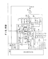
- Fig. 16 is a circuit diagram of one form of the microwave oven control circuit including a microcomputer 31-a as a_control means.
- a start button 32 Upon depression of a start button 32 (Fig. 4), a start switch 33 is closed to close a contact 34-a and open a contact 34-b of a semiconductor switch 34, and an amplifier 35 for the humidity sensing purpose is selected, while, at the same time, a refreshing operation relay 36 is energized.
- the refreshing operation relay 36 is deenergized to change over the voltage applied across the heater 14.
- the start button 32 is depressed after depression of a grill key 37 (Fig.
- the power supply voltage is applied across the primary side of a high-voltage transformer 45 to induce a high voltage in the secondary side of the transformer 45 thereby causing oscillation of the magnetron 1.
- the microcomputer 31-a detects or calculates AV in Fig. 13 on the basis of the information including the output voltage of a comparator 47 and the reference voltage applied to the comparator 47 and fimally deenergizes the relay 44 to end the cooking operation.
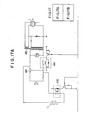
- the coil of a relay 48 is energized to energize the heater 11 disposed outside of the oven chamber 3.
- the microcomputer 31-a detects or calculates ⁇ V in Fig. 15 on the basis of the information including the output voltage of the comparator 47 and the reference voltage applied to the comparator 47 and finally deenergizes the relay 48 to end the cooking operation.
- Fig. 19 shows a modification of the ceramic gas sensor 9 shown in Fig. 5.
- the coil heater 14 is replaced by a plane one 48, and such a plane heater 48 is mounted on the surface of the sensing part 13 of the ceramic gas sensor 9.
- the present invention comprises a ceramic gas sensor, means for changing the level of heat applied to the sensing part of the ceramic gas sensor, and amplifiers having different gains.
- the single sensor can sense both of a change in the relative humidity of air in the oven chamber due to vapor given off from materials being cooked and volatile matters contained in soot given off from the materials being cooked.
- the present invention is therefore advantageous in that the state of cooking a "grill menu", which could not be sensed by resorting only to the humidity sensing characteristic of a prior art unifunctional gas sensor, can be automatically sensed so that the microwave oven can be used for the cooking of a variety of menus.
Landscapes
- Physics & Mathematics (AREA)
- Electromagnetism (AREA)
- Electric Ovens (AREA)
- Control Of High-Frequency Heating Circuits (AREA)
- Investigating Or Analyzing Materials By The Use Of Fluid Adsorption Or Reactions (AREA)
Applications Claiming Priority (2)
| Application Number | Priority Date | Filing Date | Title |
|---|---|---|---|
| JP168851/79 | 1979-12-24 | ||
| JP16885179A JPS5691716A (en) | 1979-12-24 | 1979-12-24 | Automatic electronic range |
Publications (2)
| Publication Number | Publication Date |
|---|---|
| EP0031156A1 true EP0031156A1 (fr) | 1981-07-01 |
| EP0031156B1 EP0031156B1 (fr) | 1984-11-21 |
Family
ID=15875715
Family Applications (1)
| Application Number | Title | Priority Date | Filing Date |
|---|---|---|---|
| EP80108055A Expired EP0031156B1 (fr) | 1979-12-24 | 1980-12-19 | Four de cuisine avec détecteur d'humidité en céramique |
Country Status (6)
| Country | Link |
|---|---|
| US (1) | US4383158A (fr) |
| EP (1) | EP0031156B1 (fr) |
| JP (1) | JPS5691716A (fr) |
| AU (1) | AU526052B2 (fr) |
| CA (1) | CA1149882A (fr) |
| DE (1) | DE3069684D1 (fr) |
Cited By (12)
| Publication number | Priority date | Publication date | Assignee | Title |
|---|---|---|---|---|
| FR2510239A1 (fr) * | 1981-07-21 | 1983-01-28 | Sharp Kk | Four combine a micro-ondes et a gril avec cuisson automatisee |
| EP0093172A4 (fr) * | 1981-11-06 | 1984-04-24 | Matsushita Electric Industrial Co Ltd | Dispositif de chauffage a haute frequence. |
| EP0093173A4 (fr) * | 1981-11-06 | 1984-04-27 | Matsushita Electric Industrial Co Ltd | Dispositif de chauffage a haute frequence. |
| US4496817A (en) * | 1983-07-07 | 1985-01-29 | General Electric Company | Automatic fire detection for a microwave oven |
| GB2158246A (en) * | 1984-03-28 | 1985-11-06 | Sharp Kk | Sensor temperature compensation |
| GB2165948A (en) * | 1984-10-23 | 1986-04-23 | Health Lab Service Board | Gas or vapour monitor |
| EP0353691A3 (fr) * | 1988-08-03 | 1991-08-21 | Matsushita Electric Industrial Co., Ltd. | Appareil de cuisson |
| EP0367186A3 (fr) * | 1988-10-31 | 1991-08-21 | Matsushita Electric Industrial Co., Ltd. | Appareil capteur pyro-électrique |
| DE4141768A1 (de) * | 1991-12-18 | 1993-06-24 | Miele & Cie | Kochherd, insbesondere mikrowellenherd |
| EP0661909A1 (fr) * | 1993-12-30 | 1995-07-05 | Lg Electronics Inc. | Appareil pour décongélation automatique pour un four à micro-ondes |
| EP2615375A1 (fr) * | 2012-01-11 | 2013-07-17 | BSH Bosch und Siemens Hausgeräte GmbH | Appareil de cuisson avec capteur pour compartiment de cuisson |
| EP3018419B1 (fr) * | 2014-11-07 | 2020-12-30 | Candy S.p.A. | Four au cuisson |
Families Citing this family (17)
| Publication number | Priority date | Publication date | Assignee | Title |
|---|---|---|---|---|
| JPS57119249A (en) * | 1981-01-16 | 1982-07-24 | Matsushita Electric Ind Co Ltd | Humidity sensor control circuit |
| CA1199076A (fr) * | 1981-07-06 | 1986-01-07 | Takeshi Tanabe | Appareil de cuisson a micro-ondes simplifiant le travail de l'utilisateur |
| JPS5813401U (ja) * | 1981-07-20 | 1983-01-27 | シャープ株式会社 | 調理器 |
| CA1200289A (fr) * | 1981-07-28 | 1986-02-04 | Takeshi Tanabe | Cuisiniere a four micro-ondes et gril |
| US4481404A (en) * | 1982-12-22 | 1984-11-06 | General Electric Company | Turn-off control circuit for self-cleaning ovens |
| JPS60131793A (ja) * | 1983-12-20 | 1985-07-13 | 松下電器産業株式会社 | 自動高周波加熱装置 |
| AU551298B2 (en) * | 1984-02-07 | 1986-04-24 | Matsushita Electric Industrial Co., Ltd. | High frequency heating apparatus |
| JPS61143630A (ja) * | 1984-12-14 | 1986-07-01 | Sharp Corp | 加熱器 |
| JPH0781715B2 (ja) * | 1986-12-17 | 1995-09-06 | 松下電器産業株式会社 | 加熱装置 |
| US4954694A (en) * | 1989-01-31 | 1990-09-04 | Matsushita Electric Industrial Co., Ltd. | Cooking oven having function to automatically clean soils attached to inner walls thereof |
| EP0397397B1 (fr) * | 1989-05-08 | 1995-01-11 | Matsushita Electric Industrial Co., Ltd. | Appareil de chauffage automatique |
| SE470168B (sv) * | 1992-04-27 | 1993-11-22 | Whirlpool Int | Rök/ångdetektor för mikrovågsugn |
| KR0154643B1 (ko) * | 1995-09-29 | 1998-11-16 | 배순훈 | 증기센서의 출력신호를 이용한 적응 제어방법 |
| US11274876B2 (en) | 2007-12-28 | 2022-03-15 | Intirion Corporation | Multiple linked appliance with auxiliary outlet |
| WO2012162685A1 (fr) * | 2011-05-26 | 2012-11-29 | Stoneridge, Inc. | Système de capteur de suie |
| US10009965B2 (en) | 2015-01-28 | 2018-06-26 | Samsung Electronics Co., Ltd. | Gas detection apparatus, cooking apparatus, and method of controlling the apparatuses |
| EP4016067B1 (fr) * | 2020-12-17 | 2024-08-28 | BSH Hausgeräte GmbH | Procédé pour déterminer l'état de fraîcheur d'un aliment dans un récipient de stockage ainsi que produit programme informatique et récipient de stockage |
Citations (1)
| Publication number | Priority date | Publication date | Assignee | Title |
|---|---|---|---|---|
| US4097707A (en) * | 1975-05-20 | 1978-06-27 | Matsushita Electric Industrial Co., Ltd. | Apparatus for controlling heating time utilizing humidity sensing |
Family Cites Families (3)
| Publication number | Priority date | Publication date | Assignee | Title |
|---|---|---|---|---|
| JPS5224770A (en) * | 1975-08-20 | 1977-02-24 | Matsushita Electric Industrial Co Ltd | Cooking oven |
| US4080564A (en) * | 1975-10-02 | 1978-03-21 | Matsushita Electric Industrial Co., Ltd. | Humidity sensitive resistor device |
| JPS55124984A (en) * | 1979-03-19 | 1980-09-26 | Sharp Kk | Cooking device |
-
1979
- 1979-12-24 JP JP16885179A patent/JPS5691716A/ja active Granted
-
1980
- 1980-12-17 US US06/217,405 patent/US4383158A/en not_active Expired - Lifetime
- 1980-12-17 AU AU65464/80A patent/AU526052B2/en not_active Ceased
- 1980-12-19 EP EP80108055A patent/EP0031156B1/fr not_active Expired
- 1980-12-19 DE DE8080108055T patent/DE3069684D1/de not_active Expired
- 1980-12-24 CA CA000367540A patent/CA1149882A/fr not_active Expired
Patent Citations (1)
| Publication number | Priority date | Publication date | Assignee | Title |
|---|---|---|---|---|
| US4097707A (en) * | 1975-05-20 | 1978-06-27 | Matsushita Electric Industrial Co., Ltd. | Apparatus for controlling heating time utilizing humidity sensing |
Non-Patent Citations (3)
| Title |
|---|
| PATENTS ABSTRACTS OF JAPAN Vol. 3, No. 116, 27 September 1979 page 13M74 & JP - A - 54 - 89345 * complete document * * |
| PATENTS ABSTRACTS OF JAPAN Vol. 3, No. 65, 6 June 1979, page 163M61 & JP - A - 54 - 43347 * complete document * * |
| PATENTS ABSTRACTS OF JAPAN Vol. 3. No. 97, 17 August 1979 page 53M69 & JP - A - 54 - 71445 * complete document * * |
Cited By (13)
| Publication number | Priority date | Publication date | Assignee | Title |
|---|---|---|---|---|
| FR2510239A1 (fr) * | 1981-07-21 | 1983-01-28 | Sharp Kk | Four combine a micro-ondes et a gril avec cuisson automatisee |
| EP0093172A4 (fr) * | 1981-11-06 | 1984-04-24 | Matsushita Electric Industrial Co Ltd | Dispositif de chauffage a haute frequence. |
| EP0093173A4 (fr) * | 1981-11-06 | 1984-04-27 | Matsushita Electric Industrial Co Ltd | Dispositif de chauffage a haute frequence. |
| US4496817A (en) * | 1983-07-07 | 1985-01-29 | General Electric Company | Automatic fire detection for a microwave oven |
| GB2158246A (en) * | 1984-03-28 | 1985-11-06 | Sharp Kk | Sensor temperature compensation |
| GB2165948A (en) * | 1984-10-23 | 1986-04-23 | Health Lab Service Board | Gas or vapour monitor |
| EP0353691A3 (fr) * | 1988-08-03 | 1991-08-21 | Matsushita Electric Industrial Co., Ltd. | Appareil de cuisson |
| EP0367186A3 (fr) * | 1988-10-31 | 1991-08-21 | Matsushita Electric Industrial Co., Ltd. | Appareil capteur pyro-électrique |
| DE4141768A1 (de) * | 1991-12-18 | 1993-06-24 | Miele & Cie | Kochherd, insbesondere mikrowellenherd |
| EP0661909A1 (fr) * | 1993-12-30 | 1995-07-05 | Lg Electronics Inc. | Appareil pour décongélation automatique pour un four à micro-ondes |
| US5519194A (en) * | 1993-12-30 | 1996-05-21 | Goldstar Co., Ltd. | Automatic thawing apparatus for a microwave oven |
| EP2615375A1 (fr) * | 2012-01-11 | 2013-07-17 | BSH Bosch und Siemens Hausgeräte GmbH | Appareil de cuisson avec capteur pour compartiment de cuisson |
| EP3018419B1 (fr) * | 2014-11-07 | 2020-12-30 | Candy S.p.A. | Four au cuisson |
Also Published As
| Publication number | Publication date |
|---|---|
| DE3069684D1 (en) | 1985-01-03 |
| CA1149882A (fr) | 1983-07-12 |
| AU526052B2 (en) | 1982-12-16 |
| US4383158A (en) | 1983-05-10 |
| AU6546480A (en) | 1981-07-02 |
| JPS6228554B2 (fr) | 1987-06-20 |
| EP0031156B1 (fr) | 1984-11-21 |
| JPS5691716A (en) | 1981-07-24 |
Similar Documents
| Publication | Publication Date | Title |
|---|---|---|
| EP0031156B1 (fr) | Four de cuisine avec détecteur d'humidité en céramique | |
| US4335293A (en) | Heating control apparatus by humidity detection | |
| US5349163A (en) | Method of automatically cooking food by detecting the amount of gas or smoke being exhausted from a cooking device during cooking | |
| US4582971A (en) | Automatic high-frequency heating apparatus | |
| US5155339A (en) | Automatic cooking method | |
| US4316068A (en) | Cooking utensil controlled by gas sensor output and thermistor output | |
| GB2105066A (en) | Microwave oven | |
| US5281786A (en) | Method of controlling cooking in microwave oven using sonic device | |
| US4501147A (en) | Control circuit for a humidity sensor | |
| JPS6340722Y2 (fr) | ||
| JP2877435B2 (ja) | 加熱調理器 | |
| JP2641436B2 (ja) | 高周波加熱装置 | |
| JPS5918319A (ja) | 加熱調理器 | |
| CA1172060A (fr) | Circuit de commande pour sonde hygrometrique | |
| JPS62150686A (ja) | 調理器 | |
| JP2521689B2 (ja) | 調理器 | |
| JPS6222050B2 (fr) | ||
| JP2548369B2 (ja) | 加熱調理器 | |
| JPH0665151B2 (ja) | 圧電素子センサ付き電子レンジ | |
| JPS58140521A (ja) | 加熱調理器 | |
| JPS6243101B2 (fr) | ||
| JPS6095882A (ja) | 調理器 | |
| JPS62112929A (ja) | 圧電素子センサ付き電子レンジ | |
| JPS59120949A (ja) | 加熱調理装置 | |
| JPS62153628A (ja) | 調理器 |
Legal Events
| Date | Code | Title | Description |
|---|---|---|---|
| PUAI | Public reference made under article 153(3) epc to a published international application that has entered the european phase |
Free format text: ORIGINAL CODE: 0009012 |
|
| AK | Designated contracting states |
Designated state(s): CH DE FR GB SE |
|
| 17P | Request for examination filed |
Effective date: 19811014 |
|
| GRAA | (expected) grant |
Free format text: ORIGINAL CODE: 0009210 |
|
| AK | Designated contracting states |
Designated state(s): CH DE FR GB LI SE |
|
| REF | Corresponds to: |
Ref document number: 3069684 Country of ref document: DE Date of ref document: 19850103 |
|
| ET | Fr: translation filed | ||
| PLBE | No opposition filed within time limit |
Free format text: ORIGINAL CODE: 0009261 |
|
| STAA | Information on the status of an ep patent application or granted ep patent |
Free format text: STATUS: NO OPPOSITION FILED WITHIN TIME LIMIT |
|
| 26N | No opposition filed | ||
| PGFP | Annual fee paid to national office [announced via postgrant information from national office to epo] |
Ref country code: GB Payment date: 19941209 Year of fee payment: 15 Ref country code: FR Payment date: 19941209 Year of fee payment: 15 |
|
| PGFP | Annual fee paid to national office [announced via postgrant information from national office to epo] |
Ref country code: CH Payment date: 19941214 Year of fee payment: 15 |
|
| PGFP | Annual fee paid to national office [announced via postgrant information from national office to epo] |
Ref country code: SE Payment date: 19941215 Year of fee payment: 15 |
|
| PGFP | Annual fee paid to national office [announced via postgrant information from national office to epo] |
Ref country code: DE Payment date: 19941222 Year of fee payment: 15 |
|
| EAL | Se: european patent in force in sweden |
Ref document number: 80108055.7 |
|
| PG25 | Lapsed in a contracting state [announced via postgrant information from national office to epo] |
Ref country code: GB Effective date: 19951219 |
|
| PG25 | Lapsed in a contracting state [announced via postgrant information from national office to epo] |
Ref country code: SE Effective date: 19951220 |
|
| PG25 | Lapsed in a contracting state [announced via postgrant information from national office to epo] |
Ref country code: LI Effective date: 19951231 Ref country code: CH Effective date: 19951231 |
|
| GBPC | Gb: european patent ceased through non-payment of renewal fee |
Effective date: 19951219 |
|
| REG | Reference to a national code |
Ref country code: CH Ref legal event code: PL |
|
| PG25 | Lapsed in a contracting state [announced via postgrant information from national office to epo] |
Ref country code: FR Effective date: 19960830 |
|
| PG25 | Lapsed in a contracting state [announced via postgrant information from national office to epo] |
Ref country code: DE Effective date: 19960903 |
|
| REG | Reference to a national code |
Ref country code: FR Ref legal event code: ST |