EP0031177B1 - Dispositif de confinement radial pour un produit allongé - Google Patents
Dispositif de confinement radial pour un produit allongé Download PDFInfo
- Publication number
- EP0031177B1 EP0031177B1 EP80201149A EP80201149A EP0031177B1 EP 0031177 B1 EP0031177 B1 EP 0031177B1 EP 80201149 A EP80201149 A EP 80201149A EP 80201149 A EP80201149 A EP 80201149A EP 0031177 B1 EP0031177 B1 EP 0031177B1
- Authority
- EP
- European Patent Office
- Prior art keywords
- circuit
- sleeve
- pressure
- annular
- product
- Prior art date
- Legal status (The legal status is an assumption and is not a legal conclusion. Google has not performed a legal analysis and makes no representation as to the accuracy of the status listed.)
- Expired
Links
Images

Classifications
-
- F—MECHANICAL ENGINEERING; LIGHTING; HEATING; WEAPONS; BLASTING
- F16—ENGINEERING ELEMENTS AND UNITS; GENERAL MEASURES FOR PRODUCING AND MAINTAINING EFFECTIVE FUNCTIONING OF MACHINES OR INSTALLATIONS; THERMAL INSULATION IN GENERAL
- F16J—PISTONS; CYLINDERS; SEALINGS
- F16J15/00—Sealings
- F16J15/16—Sealings between relatively-moving surfaces
- F16J15/168—Sealings between relatively-moving surfaces which permits material to be continuously conveyed
-
- B—PERFORMING OPERATIONS; TRANSPORTING
- B29—WORKING OF PLASTICS; WORKING OF SUBSTANCES IN A PLASTIC STATE IN GENERAL
- B29C—SHAPING OR JOINING OF PLASTICS; SHAPING OF MATERIAL IN A PLASTIC STATE, NOT OTHERWISE PROVIDED FOR; AFTER-TREATMENT OF THE SHAPED PRODUCTS, e.g. REPAIRING
- B29C37/00—Component parts, details, accessories or auxiliary operations, not covered by group B29C33/00 or B29C35/00
- B29C37/0089—Sealing devices placed between articles and treatment installations during moulding or shaping, e.g. sealing off the entrance or exit of ovens or irradiation rooms, connections between rooms at different pressures
-
- B—PERFORMING OPERATIONS; TRANSPORTING
- B29—WORKING OF PLASTICS; WORKING OF SUBSTANCES IN A PLASTIC STATE IN GENERAL
- B29C—SHAPING OR JOINING OF PLASTICS; SHAPING OF MATERIAL IN A PLASTIC STATE, NOT OTHERWISE PROVIDED FOR; AFTER-TREATMENT OF THE SHAPED PRODUCTS, e.g. REPAIRING
- B29C48/00—Extrusion moulding, i.e. expressing the moulding material through a die or nozzle which imparts the desired form; Apparatus therefor
- B29C48/03—Extrusion moulding, i.e. expressing the moulding material through a die or nozzle which imparts the desired form; Apparatus therefor characterised by the shape of the extruded material at extrusion
- B29C48/06—Rod-shaped
-
- B—PERFORMING OPERATIONS; TRANSPORTING
- B29—WORKING OF PLASTICS; WORKING OF SUBSTANCES IN A PLASTIC STATE IN GENERAL
- B29C—SHAPING OR JOINING OF PLASTICS; SHAPING OF MATERIAL IN A PLASTIC STATE, NOT OTHERWISE PROVIDED FOR; AFTER-TREATMENT OF THE SHAPED PRODUCTS, e.g. REPAIRING
- B29C48/00—Extrusion moulding, i.e. expressing the moulding material through a die or nozzle which imparts the desired form; Apparatus therefor
- B29C48/25—Component parts, details or accessories; Auxiliary operations
- B29C48/88—Thermal treatment of the stream of extruded material, e.g. cooling
- B29C48/885—External treatment, e.g. by using air rings for cooling tubular films
-
- B—PERFORMING OPERATIONS; TRANSPORTING
- B29—WORKING OF PLASTICS; WORKING OF SUBSTANCES IN A PLASTIC STATE IN GENERAL
- B29C—SHAPING OR JOINING OF PLASTICS; SHAPING OF MATERIAL IN A PLASTIC STATE, NOT OTHERWISE PROVIDED FOR; AFTER-TREATMENT OF THE SHAPED PRODUCTS, e.g. REPAIRING
- B29C48/00—Extrusion moulding, i.e. expressing the moulding material through a die or nozzle which imparts the desired form; Apparatus therefor
- B29C48/25—Component parts, details or accessories; Auxiliary operations
- B29C48/88—Thermal treatment of the stream of extruded material, e.g. cooling
- B29C48/90—Thermal treatment of the stream of extruded material, e.g. cooling with calibration or sizing, i.e. combined with fixing or setting of the final dimensions of the extruded article
-
- B—PERFORMING OPERATIONS; TRANSPORTING
- B29—WORKING OF PLASTICS; WORKING OF SUBSTANCES IN A PLASTIC STATE IN GENERAL
- B29C—SHAPING OR JOINING OF PLASTICS; SHAPING OF MATERIAL IN A PLASTIC STATE, NOT OTHERWISE PROVIDED FOR; AFTER-TREATMENT OF THE SHAPED PRODUCTS, e.g. REPAIRING
- B29C48/00—Extrusion moulding, i.e. expressing the moulding material through a die or nozzle which imparts the desired form; Apparatus therefor
- B29C48/25—Component parts, details or accessories; Auxiliary operations
- B29C48/88—Thermal treatment of the stream of extruded material, e.g. cooling
- B29C48/90—Thermal treatment of the stream of extruded material, e.g. cooling with calibration or sizing, i.e. combined with fixing or setting of the final dimensions of the extruded article
- B29C48/907—Thermal treatment of the stream of extruded material, e.g. cooling with calibration or sizing, i.e. combined with fixing or setting of the final dimensions of the extruded article using adjustable calibrators, e.g. the dimensions of the calibrator being changeable
-
- B—PERFORMING OPERATIONS; TRANSPORTING
- B29—WORKING OF PLASTICS; WORKING OF SUBSTANCES IN A PLASTIC STATE IN GENERAL
- B29C—SHAPING OR JOINING OF PLASTICS; SHAPING OF MATERIAL IN A PLASTIC STATE, NOT OTHERWISE PROVIDED FOR; AFTER-TREATMENT OF THE SHAPED PRODUCTS, e.g. REPAIRING
- B29C48/00—Extrusion moulding, i.e. expressing the moulding material through a die or nozzle which imparts the desired form; Apparatus therefor
- B29C48/03—Extrusion moulding, i.e. expressing the moulding material through a die or nozzle which imparts the desired form; Apparatus therefor characterised by the shape of the extruded material at extrusion
- B29C48/09—Articles with cross-sections having partially or fully enclosed cavities, e.g. pipes or channels
-
- B—PERFORMING OPERATIONS; TRANSPORTING
- B29—WORKING OF PLASTICS; WORKING OF SUBSTANCES IN A PLASTIC STATE IN GENERAL
- B29K—INDEXING SCHEME ASSOCIATED WITH SUBCLASSES B29B, B29C OR B29D, RELATING TO MOULDING MATERIALS OR TO MATERIALS FOR MOULDS, REINFORCEMENTS, FILLERS OR PREFORMED PARTS, e.g. INSERTS
- B29K2021/00—Use of unspecified rubbers as moulding material
Definitions
- the present invention relates to a device for the radial confinement of an elongated product with a cylindrical lateral surface, movable longitudinally continuously, comprising a flexible sleeve which the elongated product passes through and compression means acting on the sleeve so that it s 'tightly fits said cylindrical side surface.
- the elongated product may have slight variations in cross-section during its production. Either its shape varies slightly, certain sections being for example slightly ovalized, or else the diameter can be slightly variable.
- the containment system must adapt to these variations.
- containment devices of the kind mentioned at the beginning can be used in other cases, for example as a bearing to support an insulated cable or an elastomeric tube or as an inlet or outlet in a cooling tank .
- a device for applications where the pressure in the enclosure is high, a device is known (GB 588 064) using as a sealing member a sleeve of deformable material surrounding the elongated product and connected by its ends to the wall of an annular chamber. Pressurized fluid could be introduced into this chamber. To avoid material contact of the sleeve with the elongated product, the pressure was adjusted in the annular chamber so that the fluid of the enclosure flows continuously, at low flow rate between the sleeve and the elongated product. For the same purpose, i.e.
- the rings are toroidal in shape, the annular spaces which they delimit with the elongated product each have a minimum section located in a plane perpendicular to the elongated product, so that the lubricating liquid undergoes, as it flows between the rings and the elongated product, variations in pressure which may create operating instabilities and mark the surface of the elongated product, even if there is no of material contact between this surface and the rings.
- the object of the present invention is to remedy the shortcomings of known containment devices by creating a simple and self-adjusting device without risking damaging the surface of the elongated product.
- the object of the present invention is characterized in that said compression means comprise two circuits of pressurized fluid, the first of which feeds an annular chamber which surrounds the sleeve and the second an annular space between the sleeve and the product.
- the present invention achieves the aim aimed at by the fact that the annular space comprised between the product to be confined and the sleeve is supplied with pressurized fluid, while a second supply of pressurized fluid compresses the sleeve radially.
- the sleeve is thus subjected to stable forces, directed radially which impose on it an equilibrium position so that its deformation is self-adjusting and that it follows the variations that the section of the elongated product can present.
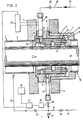
- the device shown in the drawing is constructed to function as the main outlet joint in a tubular enclosure 1 used for vulcanizing and cooling an electric cable 18.
- the latter receives its layer of insulation at the entry of the line in a extrusion head (not shown).
- the vulcanization line 1 comprises a tube 2 provided with a flange 3.
- the device which will be described is fixed to this flange. It comprises an annular support member 4 held for example by screws (not shown) against the flange 3.
- a flexible elastomer sleeve 5 fixed for example by vulcanization between a front metal ring 6 and a rear metal ring 7, the assembly being engaged in inside of the support 4 and retained in place by the lateral flange 6a of the part 6 and by the screws 8 which apply the annular blocking plate 9 axially against the support 4.
- the line described also comprises an outlet chamber designated generally by 10 and whose upstream flange 11 engages on the annular support 4 so as to be able to be fixed to the flange 3. This outlet chamber is not part of the device described.
- the annular support 4 has an internal groove 12 which defines with the outer surface of the sleeve 5 an annular chamber of small thickness surrounding the entire sleeve. This chamber is closed in a sealed manner by sealing rings 13 which are housed in grooves in the support 4 and which cooperate with the external surface of the rings 6 and 7.
- Its internal surface 17 which is normally at a predetermined distance from the external surface of the insulated cable 18 treated in the enclosure 1, contracts and its distance from the cable decreases.
- the containment device described comprises a pressurized water circuit designated by 19.
- the water pipe is connected by a connector 20 to a radial bore 21 formed in the support 4.
- This bore opens into a groove 22 formed in the ring 6 and capable of supplying axial holes 23 formed at mid-height in the sleeve 5 and distributed around the axis of the device. In the middle of their length, these axial holes 23 communicate with the bottom of a groove 24 which is formed in the inner face 17 of the sleeve 5, approximately in the middle of its length.
- the air pressure in circuit 16 must be higher than the pressure prevailing in the vulcanization enclosure 1.
- the cricuit 16 is equipped with valves 25 and 26 and is connected by a tube 27 to tube 1. It also has a adjustment valve 28 and an adjustable exhaust port 29. Its supply of pressurized fluid comes from piping 31.
- the fluid of circuit 16 could also, as a variant, be water.
- the pressure ratio will be equal to the ratio between the outside and inside diameters of the sleeve 5. It will be understood that, like the drillings 23 are constantly filled with water, the deformation of the sleeve 5 under the effect of the pressure prevailing in the chamber 12 is a radial deformation whose amplitude is maximum in the center of the sleeve, that is to say on the part and other side of the groove 24.
- the deformation of the sleeve immediately increases under the effect of the pressure prevailing in the chamber 12 and a new balance of forces is established for a deformation of the sleeve a little greater than previous ence.
- This provides a self-adjusting containment device with safe operation and simple construction. This device adapts automatically and instantly to variations in cable size and shape.
- This self-compensating effect determines the difference in pressures prevailing in the chamber 12 and in the annular space 37. If the section of cable which passes through the device has a relatively large diameter, the pressure in the space 37, and consequently , in the groove 22 and the conduit 20, is relatively high. The difference between the pressures in the chamber 12 and in the space 37 is relatively small and the deformation of the sleeve 5 is small. If, on the other hand, the section of the cable which passes through the device has a small diameter, the pressure in the space 37 is low and the difference between the pressures in the chamber 12 and in the space 37 is large, which causes a large deformation of the sleeve 5.
- the variation range described above depends on the pressure in the chamber 12, which is determined, on the one hand, by the pressure in the enclosure 1, transmitted by the line 27 to the valve 25 , and on the other hand, by the position of the valve 28.
- the value of the pressure at any point of the circuit 19, between the valve 30 and the conduits 23, is a measure of the leakage rate through the groove 24 and space 37.
- the pressure in the chamber 12 there is a pressure drop between the inlet part and the internal part of the circuit 19, due to the presence of the ball valve 30 and this pressure drop depends directly on the height of the clearance between the cable and the internal surface 17 of the sleeve 5.
- a pressure gauge 33 can be a direct reading pressure gauge which gives the value of the pressure to the installation supervisor, or a pressure gauge control which emits electrical or hydraulic signals corresponding to the pressure measured.
- the installation supervisor will act on the valve 28 according to the indications read on the pressure gauge 33, so as to maintain it at a fixed, setpoint value.
- control device may be supplemented by a comparator 34 which compares the indication of the pressure gauge 33 with a transmitter 35 a setpoint and by a control member 36 acting on the valve 28 so as to maintain the pressure gauge 33 at a value close to the setpoint, thereby adjusting the leak rate to a predetermined value.
- the two air and water circuits instead of being entirely independent, could be connected to each other.
- the same fluid could be used, one of the circuits being derived from the first through a pressure reduction valve.
- the pressures prevailing along the two circuits, downstream of the valves are determined by the characteristics of the circuits, that is to say the adjustment of the valve 28 and of the orifice 29, the characteristics of deformation of the material of the sleeve 5, the dimensions of this sleeve and the thickness of the space 37.
- the sleeve deforms and takes a position of equilibrium which is determined by the equality of the opposing radial forces which it undergoes. Therefore, the pressures in the circuits 19 and 16 upstream of the valves 30 and 26 can be equal, and as one can use the same fluid in the two circuits, these can be connected to a common source.
Landscapes
- Engineering & Computer Science (AREA)
- Mechanical Engineering (AREA)
- Physics & Mathematics (AREA)
- Thermal Sciences (AREA)
- General Engineering & Computer Science (AREA)
- Heating, Cooling, Or Curing Plastics Or The Like In General (AREA)
- Machine Tool Units (AREA)
Description
- La présente invention a pour objet un dispositif de confinement radial d'un produit allongé à surface latérale cylindrique, mobile longitudinalement en continu, comportant un manchon souple que le produit allongé traverse et des moyens de compression agissant sur le manchon de manière qu'il s'adapte étroitement à ladite surface latérale cylindrique.
- Le problème du confinement radial d'un produit allongé tel qu'un câble revêtu d'une couche isolante en élastomère ou un tube en élastomère se pose notamment dans la construction des lignes de vulcanisation de ces produits. Ces lignes comportent une enceinte tubulaire de grande longueur qui contient une atmosphère de gaz sous pression ou, dans leur partie inférieure, un liquide de refroidissement et le câble doit être conduit à travers un orifice de sortie sans que sa surface extérieure soit détériorée par le contact d'objets rigides mais en évitant les fuites de fluide sous pression.
- Un des éléments qui compliquent la solution de ce problème est le fait que le produit allongé peut présenter de légères variations de section au cours de sa production. Ou bien sa forme varie légèrement, certains tronçons étant par exemple légèrement ovalisés, ou bien le diamètre peut être légèrement variable. Le dispositif de confinement doit s'adapter à ces variations.
- Toutefois, des dispositifs de confinement du genre mentionné au début peuvent être utilisés dans d'autres cas, par exemple en guise de palier pour supporter un câble isolé ou un tube en élastomère ou comme orifice d'entrée ou de sortie dans un bac de refroidissement.
- Les brevets CH 582 408, GB-A-2 014 255 et FR 2406874 décrivent des dispositifs dans lesquels plusieurs anneaux en élastomère espacés le long du produit allongé sont comprimés de façon à l'enserrer plus ou moins. Ces dispositifs ne conviennent toutefois pas si la pression dans l'enceinte tubulaire est relativement élevée et si la surface du produit allongé est dans un état tel, au moment où ce produit traverse le dispositif de confinement, qu'elle risque d'être détériorée par le contact des anneaux.
- Pour des applications où la pression dans l'enceinte est élevée on connaissait un dispositif (GB 588 064) utilisant comme organe d'étanchéité un manchon en matériau déformable entourant le produit allongé et relié par ses extrémités à la paroi d'une chambre annulaire. Un fluide sous pression pouvait être introduit dans cette chambre. Pour éviter le contact matériel du manchon avec le produit allongé, la pression était réglée dans la chambre annulaire de façon que le fluide de l'enceinte s'écoule en permanence, à faible débit entre le manchon et le produit allongé. Dans le même but, c.à.d. réduire les fuites de fluide hors de l'enceinte tout en évitant un contact matériel avec le produit allongé, on connaissait également (DE-OS-2737182) un dispositif de confinement dans lequel le produit allongé traverse successivement une série d'anneaux tubulaires en caoutchouc, à section circulaire, raccordés à une première source de fluide qui est de l'air comprimé. Ces anneaux sont répartis par groupes qui délimitent entre eux des chambres intermédiaires et une seconde source de fluide sous pression envoie dans une chambre centrale un liquide lubrifiant qui est récolté dans une autre chambre située en aval. Avec ce dernier dispositif, les fuites du fluide contenu dans l'enceinte sont évitées, mais du fait que les anneaux sont de forme torique, les espaces annulaires qu'ils délimitent avec le produit allongé présentent chacun une section minimale située dans un plan perpendiculaire au produit allongé, de sorte que le liquide lubrifiant subit en s'écoulant entre les anneaux et le produit allongé des variations de pression susceptibles de créer des instabilités de fonctionnement et de marquer la surface du produit allongé, même s'il n'y a pas de contact matériel entre cette surface et les anneaux.
- Le but de la présente invention est de remédier aux défauts des dispositifs de confinement connus en créant un dispositif simple et auto-réglant sans risquer de détériorer la surface du produit allongé.
- Dans ce but, l'objet de la présente invention, du genre précédemment mentionné, est caractérisé en ce que lesdits moyens de compression comportent deux circuits de fluide sous pression dont le premier alimente une chambre annulaire qui entoure le manchon et le second un espace annulaire compris entre le manchon et le produit.
- Ainsi, tout en utilisant comme organe de confinement un manchon souple, et non pas une série d'anneaux comme la plupart des dispositifs connus antérieurement, la présente invention atteint le but visé par le fait que l'espace annulaire compris entre le produit à confiner et le manchon est alimenté en fluide sous pression, alors qu'une seconde alimentation en fluide sous pression comprime le manchon radialement. Le manchon est ainsi soumis à des forces stables, dirigées radialement qui lui imposent une position d'équilibre de sorte que sa déformation est auto-réglée et qu'il suit les variations que la section du produit allongé peut présenter.
- On va décrire ci-après, à titre d'exemple, une forme d'exécution du dispositif selon l'invention et une variante en se référant au dessin annexé, dont:
- la fig. 1 est une vue en coupe axiale du dispositif, et
- la fig. 2 une vue semblable de la variante.
- Le dispositif représenté au dessin est construit pour fonctionner comme joint de sortie principal dans une enceinte tubulaire 1 servant à la vulcanisation et au refroidissement d'un câble électrique 18. Ce dernier reçoit sa couche d'isolation à l'entrée de la ligne dans une tête d'extrusion (non représentée). A son extrémité inférieure, la ligne de vulcanisation 1 comporte un tube 2 muni d'une bride 3. Le dispositif qui va être décrit est fixé à cette bride. Il comporte un organe de support annulaire 4 maintenu par exemple par des vis (non représentées) contre la bride 3. A l'intérieur de cet organe est logé un manchon souple en élastomère 5 fixé par exemple par vulcanisation entre une bague métallique avant 6 et une bague métallique arrière 7, l'ensemble étant engagé à l'intérieur du support 4 et retenu en place par la bride latérale 6a de la pièce 6 et par les vis 8 qui appliquent la plaque annulaire de blocage 9 axialement contre le support 4. La ligne décrite comporte en outre une chambre de sortie désignée de façon générale par 10 et dont la bride amont 11 s'engage sur le support annulaire 4 de façon à pouvoir être fixé à la bride 3. Cette chambre de sortie ne fait pas partie du dispositif décrit.
- Le support annulaire 4 présente une gorge interne 12 qui délimite avec la surface extérieure du manchon 5 une chambre annulaire de faible épaisseur entourant tout le manchon. Cette chambre est fermée de façon étanche par des anneaux d'étanchéité 13 qui sont logés dans des gorges du support 4 et qui coopèrent avec la surface extérieure des bagues 6 et 7. Une forure radiale 14 ménagée dans le support 4, et reliée par un raccord 15 à un circuit d'alimentation en air sous pression 16, permet de faire agir dans cette chambre une pression d'air réglable, de sorte que le manchon se déforme radialement dans le sens centripète. Sa surface interne 17 qui se trouve normalement à une distance prédéterminée de la surface externe du câble isolé 18 traité dans l'enceinte 1, se contracte et sa distance au câble diminue.
- En outre, le dispositif de confinement décrit comporte un circuit d'eau sous pression désigné par 19. La canalisation d'eau est connectée par un raccord 20 à une forure radiale 21 ménagée dans le support 4. Cette forure débouche dans une gorge 22 ménagée dans la bague 6 et capable d'alimenter des forures axiales 23 ménagées à mi-hauteur dans le manchon 5 et réparties autour de l'axe du dispositif. Au milieu de leur longueur ces forures axiales 23 communiquent avec le fond d'une gorge 24 qui est ménagée dans la face intérieure 17 du manchon 5, à peu près au milieu de sa longueur.
- La pression de l'air dans le circuit 16 doit être supérieure à la pression régnant dans l'enceinte du vulcanisation 1. Le cricuit 16 est équipé des soupapes 25 et 26 et est raccordé par une tubulure 27 au tube 1. Il comporte encore une vanne de réglage 28 et un orifice d'échappement réglable 29. Son alimentation en fluide sous pression provient de la tuyauterie 31. Le fluide du circuit 16 pourrait aussi, en variante, être de l'eau. Quant au circuit 19, il est également fermé par une soupape à bille 30 qui laisse entrer l'eau quand la pression interne dans le circuit est inférieure à celle qui règne dans la conduite 32 d'alimentation. On ajustera celle-ci à une valeur suffisante de façon qu'il s'établisse un équilibre entre les forces exercées sur le manchon 5, d'une part, par le film liquide qui s'écoule dans l'espace annulaire 37 situé entre 1e câble 18 et la surface 17, et d'autre part, par l'air sous pression contenu dans la chambre 12. Le rapport des pressions sera égal au rapport entre les diamètres extérieur et intérieur du manchon 5. On conçoit que, comme les forures 23 sont constamment remplies d'eau, la déformation du manchon 5 sous l'effet de la pression régnant dans la chambre 12 est une déformation radiale dont l'amplitude est maximale au centre du manchon, c'est-à-dire de part et d'autre de la gorge 24. Si le débit de fuite augmente, par exemple du fait d'une réduction du diamètre de l'isolant, immédiatement la déformation du manchon s'amplifie sous l'effet de la pression régnant dans la chambre 12 et un nouvel équilibre des forces s'établit pour une déformation du manchon un peu plus grande que précédemment. On obtient ainsi un dispositif de confinement auto-réglé d'un fonctionnement sûr et d'une construction simple. Ce dispositif s'adapte automatiquement et instantanément aux variations de dimensions et de forme du câble.
- Cet effet d'autocompensation détermine la différence des pressions régnant dans la chambre 12 et dans l'espace annulaire 37. Si le tronçon de câble qui passe dans le dispositif a un diamètre relativement grand, la pression dans l'espace 37, et par conséquent, dans la gorge 22 et le conduit 20, est relativement élevée. La différence entre les pressions dans la chambre 12 et dans l'espace 37 est relativement faible et la déformation du manchon 5 est faible. Si, en revanche, le tronçon du câble qui traverse le dispositif a un faible diamètre, la pression dans l'espace 37 est faible et la différence entre les pressions dans la chambre 12 et dans l'espace 37 est grande, ce qui provoque une grande déformation du manchon 5. La plage de variation décrite ci-dessus dépend de la pression dans la chambre 12, qui est déterminée, d'une part, par la pression dans l'enceinte 1, transmise par la conduite 27 à la soupape 25, et d'autre part, par la position de la vanne 28.
- On conçoit maintenant, et c'est un aspectsecon- daire de la présente invention, que la valeur de la pression à un point quelconque du circuit 19, entre la soupape 30 et les conduits 23, est une mesure du débit de fuite à travers la gorge 24 et l'espace 37. Indépendamment de la pression dans la chambre 12, il se produit une chute de pression entre la partie d'entrée et la partie interne du circuit 19, du fait de la présence de la soupape à bille 30 et cette chute de pression dépend directement de la hauteur du jeu entre le câble et la surface interne 17 du manchon 5.
- On prévoit donc, dans la variante d'exécution représentée à la fig. 2 de raccorder un point du circuit 19, par exemple le raccord 20 à un manomètre 33. Il peut s'agir d'un manomètre à lecture directe qui donne la valeur de la pression au surveillant de l'installation, ou d'un manomètre de réglage qui émet des signaux électriques ou hydrauliques correspondant à la pression mesurée. Dans le premier cas, le surveillant de l'installation agira sur la vanne 28 en fonction des indications lues sur le manomètre 33, de manière à la maintenir à une valeur fixe, de consigne. Dans le second cas, on pourra compléter le dispositif de commande par un comparateur 34 qui compare l'indication du manomètre 33 avec un émetteur 35 d'une valeur de consigne et par un organe de commande 36 agissant sur la vanne 28 de manière à maintenir le manomètre 33 à une valeur proche de la valeur de consigne, en réglant ainsi le débit de fuite à une valeur prédéterminée.
- D'autres formes d'exécution peuvent également être imaginées. Ainsi, les deux circuits d'air et d'eau, au lieu d'être entièrement indépendants, pourraient être connectés l'un à l'autre. Dans les deux circuits, on pourrait utiliser le même fluide, l'un des circuits étant dérivé du premier à travers une soupape de réduction de pression.
- En effet, il résulte des explications données au sujet de la forme d'exécution des figs 1 et 2 que du fait des soupapes à bille 30, 26 et 25 les pressions régant le long des deux circuits, à l'aval des soupapes, sont déterminées par les caractéristiques des circuits, c'est-à-dire l'ajustage de la vanne 28 et de l'orifice 29, les caractéristiques de déformation du matériau du manchon 5, les dimensions de ce manchon et l'épaisseur de l'espace 37. Comme on l'a dit plus haut, le manchon se déforme et prend une position d'équilibre qui est déterminée par l'égalité des forces radiales antagonistes qu'il subit. De ce fait, les pressions dans les circuits 19 et 16 à l'amont des soupapes 30 et 26 peuvent être égales, et comme on peut utiliser le même fluide dans les deux circuits, ceux-ci peuvent être reliés à une source commune.
Claims (10)
Applications Claiming Priority (2)
| Application Number | Priority Date | Filing Date | Title |
|---|---|---|---|
| CH11437/79 | 1979-12-21 | ||
| CH1143779A CH639029A5 (fr) | 1979-12-21 | 1979-12-21 | Dispositif de confinement radial pour un produit allonge et utilisation de ce dispositif. |
Publications (3)
| Publication Number | Publication Date |
|---|---|
| EP0031177A2 EP0031177A2 (fr) | 1981-07-01 |
| EP0031177A3 EP0031177A3 (en) | 1982-06-30 |
| EP0031177B1 true EP0031177B1 (fr) | 1984-08-01 |
Family
ID=4373490
Family Applications (1)
| Application Number | Title | Priority Date | Filing Date |
|---|---|---|---|
| EP80201149A Expired EP0031177B1 (fr) | 1979-12-21 | 1980-12-04 | Dispositif de confinement radial pour un produit allongé |
Country Status (3)
| Country | Link |
|---|---|
| EP (1) | EP0031177B1 (fr) |
| CH (1) | CH639029A5 (fr) |
| DE (1) | DE3068818D1 (fr) |
Families Citing this family (1)
| Publication number | Priority date | Publication date | Assignee | Title |
|---|---|---|---|---|
| AU2002216306A1 (en) * | 2001-12-20 | 2003-07-09 | Thomas Edward Saunders | Apparatus and method for cooling an extruded strip of plastics material |
Citations (1)
| Publication number | Priority date | Publication date | Assignee | Title |
|---|---|---|---|---|
| FR888919A (fr) * | 1942-08-14 | 1943-12-27 | Delore Sa Geoffroy | Perfectionnements aux appareils de vulcanisation en continu pour câbles électriques, fils, profilés et produits analogues |
Family Cites Families (8)
| Publication number | Priority date | Publication date | Assignee | Title |
|---|---|---|---|---|
| US2307575A (en) * | 1941-04-18 | 1943-01-05 | Benjamin H Davis | Apparatus for treating continuously sheathed cores |
| FR888910A (fr) * | 1942-08-12 | 1943-12-27 | Cfcmug | Perfectionnements aux interrupteurs automatiques |
| GB588064A (en) * | 1944-01-28 | 1947-05-13 | Bakelite Ltd | Improvements in means for controlling escape of fluid from a container along an element passing therethrough |
| US2825589A (en) * | 1954-10-18 | 1958-03-04 | British Insulated Callenders | Sealing glands |
| US3868104A (en) * | 1973-07-26 | 1975-02-25 | Little Inc A | Contactless fluid seal |
| GB1504355A (en) * | 1974-11-29 | 1978-03-22 | Scholz Gmbh Co Kg Maschbau | Vulcanising device |
| DE2737182C2 (de) * | 1977-08-18 | 1987-04-02 | Paul Troester Maschinenfabrik, 3000 Hannover | Verfahren und Vorrichtung zur thermischen Behandlung von extrudiertem Gut |
| FI55591C (fi) * | 1977-10-21 | 1979-08-10 | Nokia Oy Ab | Taetningshuvud foer ett behandlingsroer foer en kabel eller liknande |
-
1979
- 1979-12-21 CH CH1143779A patent/CH639029A5/fr not_active IP Right Cessation
-
1980
- 1980-12-04 DE DE8080201149T patent/DE3068818D1/de not_active Expired
- 1980-12-04 EP EP80201149A patent/EP0031177B1/fr not_active Expired
Patent Citations (1)
| Publication number | Priority date | Publication date | Assignee | Title |
|---|---|---|---|---|
| FR888919A (fr) * | 1942-08-14 | 1943-12-27 | Delore Sa Geoffroy | Perfectionnements aux appareils de vulcanisation en continu pour câbles électriques, fils, profilés et produits analogues |
Also Published As
| Publication number | Publication date |
|---|---|
| DE3068818D1 (en) | 1984-09-06 |
| EP0031177A3 (en) | 1982-06-30 |
| CH639029A5 (fr) | 1983-10-31 |
| EP0031177A2 (fr) | 1981-07-01 |
Similar Documents
| Publication | Publication Date | Title |
|---|---|---|
| EP4155597B1 (fr) | Canalisation d'hydrogène à double peau comprenant au moins un système de détection de fuite au niveau d'au moins un système de raccordement, aéronef comprenant au moins une telle canalisation | |
| WO2001081813A1 (fr) | Embout d'etancheite pour conduit tubulaire | |
| EP0200666A1 (fr) | Dispositif de raccordement instantané pour tubes en matières plastique et métallique | |
| EP0258129A1 (fr) | Perfectionnements aux dispositifs mélangeurs thermostatiques, en particulier pour la distribution d'eau | |
| EP0319371B1 (fr) | Dispositif de guidage cylindrique à compensation de jeu de fonctionnement pour système d'injection de combustible | |
| EP0328472B1 (fr) | Raccord-démarreur pour la mise en pression progressive d'installations pneumatiques | |
| FR2493954A1 (fr) | ||
| EP0031177B1 (fr) | Dispositif de confinement radial pour un produit allongé | |
| WO2020225262A1 (fr) | Tête de réservoir pour gaz sous pression | |
| EP0084308A2 (fr) | Dispositif de régulation d'un réfrigérateur à effet Joule-Thomson | |
| FR2793081A1 (fr) | Dispositif d'etancheite du type presse-garniture pour un cable | |
| EP0446547B1 (fr) | Dispostif de mesure pneumatique | |
| WO2023187212A1 (fr) | Tête de connexion rapportable sur une ouverture d'un élément de tuyauterie à bride pour son contrôle sous pression | |
| FR2557294A1 (fr) | Appareil de detection de fuites de raccords de tuyauteries | |
| FR2681931A1 (fr) | Raccord a soupape, en particulier raccord de mesure pour circuits de fluide sous hautes tensions. | |
| EP0478421B1 (fr) | Dispositif d'étanchéité à joint fluide | |
| BE1008357A3 (fr) | Tuyauterie comportant un tuyau interieur et un tuyau exterieur. | |
| EP0059131A1 (fr) | Elément de liaison entre une pompe primaire et le conduit de refoulement pour surrégénérateur de type piscine | |
| FR2505013A1 (fr) | Mecanisme de commande notamment pour vanne a gaz | |
| FR2560340A1 (fr) | Regulateur de pression de gaz et installation pour maintenir une pression de gaz dans une enceinte | |
| FR3078361A1 (fr) | Ensemble d'etancheite dispose entre deux parties separees et successives d'une virole de turbomachine | |
| FR2466800A1 (fr) | Soupape | |
| CA1297923C (fr) | Raccord tournant et etanche pour fluide sous pression | |
| FR2501825A1 (fr) | Dispositif de compensation ou de rattrapage des dilatations et contractions d'une conduite | |
| EP0070227B1 (fr) | Dispositif de vérin hydraulique, annulaire, notamment pour la commande d'un mandrin de serrage de pièce sur une machine-outil |
Legal Events
| Date | Code | Title | Description |
|---|---|---|---|
| PUAI | Public reference made under article 153(3) epc to a published international application that has entered the european phase |
Free format text: ORIGINAL CODE: 0009012 |
|
| AK | Designated contracting states |
Designated state(s): CH DE FR GB LI |
|
| PUAL | Search report despatched |
Free format text: ORIGINAL CODE: 0009013 |
|
| AK | Designated contracting states |
Designated state(s): CH DE FR GB LI |
|
| 17P | Request for examination filed |
Effective date: 19820707 |
|
| GRAA | (expected) grant |
Free format text: ORIGINAL CODE: 0009210 |
|
| AK | Designated contracting states |
Designated state(s): CH DE FR GB LI |
|
| REF | Corresponds to: |
Ref document number: 3068818 Country of ref document: DE Date of ref document: 19840906 |
|
| PLBE | No opposition filed within time limit |
Free format text: ORIGINAL CODE: 0009261 |
|
| STAA | Information on the status of an ep patent application or granted ep patent |
Free format text: STATUS: NO OPPOSITION FILED WITHIN TIME LIMIT |
|
| 26N | No opposition filed | ||
| PGFP | Annual fee paid to national office [announced via postgrant information from national office to epo] |
Ref country code: FR Payment date: 19941108 Year of fee payment: 15 |
|
| PGFP | Annual fee paid to national office [announced via postgrant information from national office to epo] |
Ref country code: GB Payment date: 19941116 Year of fee payment: 15 |
|
| PGFP | Annual fee paid to national office [announced via postgrant information from national office to epo] |
Ref country code: DE Payment date: 19941122 Year of fee payment: 15 |
|
| PGFP | Annual fee paid to national office [announced via postgrant information from national office to epo] |
Ref country code: CH Payment date: 19941202 Year of fee payment: 15 |
|
| PG25 | Lapsed in a contracting state [announced via postgrant information from national office to epo] |
Ref country code: GB Effective date: 19951204 |
|
| PG25 | Lapsed in a contracting state [announced via postgrant information from national office to epo] |
Ref country code: LI Effective date: 19951231 Ref country code: CH Effective date: 19951231 |
|
| GBPC | Gb: european patent ceased through non-payment of renewal fee |
Effective date: 19951204 |
|
| REG | Reference to a national code |
Ref country code: CH Ref legal event code: PL |
|
| PG25 | Lapsed in a contracting state [announced via postgrant information from national office to epo] |
Ref country code: FR Effective date: 19960830 |
|
| PG25 | Lapsed in a contracting state [announced via postgrant information from national office to epo] |
Ref country code: DE Effective date: 19960903 |
|
| REG | Reference to a national code |
Ref country code: FR Ref legal event code: ST |