EP0031594A2 - Installation de transmission de courant continu à haute tension - Google Patents
Installation de transmission de courant continu à haute tension Download PDFInfo
- Publication number
- EP0031594A2 EP0031594A2 EP80108227A EP80108227A EP0031594A2 EP 0031594 A2 EP0031594 A2 EP 0031594A2 EP 80108227 A EP80108227 A EP 80108227A EP 80108227 A EP80108227 A EP 80108227A EP 0031594 A2 EP0031594 A2 EP 0031594A2
- Authority
- EP
- European Patent Office
- Prior art keywords
- voltage
- limiting
- polarity
- direct current
- transmission system
- Prior art date
- Legal status (The legal status is an assumption and is not a legal conclusion. Google has not performed a legal analysis and makes no representation as to the accuracy of the status listed.)
- Granted
Links
Images

Classifications
-
- H—ELECTRICITY
- H02—GENERATION; CONVERSION OR DISTRIBUTION OF ELECTRIC POWER
- H02J—ELECTRIC POWER NETWORKS; CIRCUIT ARRANGEMENTS OR SYSTEMS FOR SUPPLYING OR DISTRIBUTING ELECTRIC POWER; SYSTEMS FOR STORING ELECTRIC ENERGY
- H02J3/00—Circuit arrangements for AC mains or AC distribution networks
- H02J3/36—Arrangements for transfer of electric power between AC networks via high-voltage DC [HVDC] links; Arrangements for transfer of electric power between generators and networks via HVDC links
-
- H—ELECTRICITY
- H02—GENERATION; CONVERSION OR DISTRIBUTION OF ELECTRIC POWER
- H02H—EMERGENCY PROTECTIVE CIRCUIT ARRANGEMENTS
- H02H7/00—Emergency protective circuit arrangements specially adapted for specific types of electric machines or apparatus or for sectionalised protection of cable or line systems, and effecting automatic switching in the event of an undesired change from normal working conditions
- H02H7/26—Sectionalised protection of cable or line systems, e.g. for disconnecting a section on which a short-circuit, earth fault, or arc discharge has occured
- H02H7/268—Sectionalised protection of cable or line systems, e.g. for disconnecting a section on which a short-circuit, earth fault, or arc discharge has occured for DC systems
-
- H—ELECTRICITY
- H02—GENERATION; CONVERSION OR DISTRIBUTION OF ELECTRIC POWER
- H02H—EMERGENCY PROTECTIVE CIRCUIT ARRANGEMENTS
- H02H9/00—Emergency protective circuit arrangements for limiting excess current or voltage without disconnection
- H02H9/04—Emergency protective circuit arrangements for limiting excess current or voltage without disconnection responsive to excess voltage
- H02H9/06—Emergency protective circuit arrangements for limiting excess current or voltage without disconnection responsive to excess voltage using spark-gap arresters
-
- Y—GENERAL TAGGING OF NEW TECHNOLOGICAL DEVELOPMENTS; GENERAL TAGGING OF CROSS-SECTIONAL TECHNOLOGIES SPANNING OVER SEVERAL SECTIONS OF THE IPC; TECHNICAL SUBJECTS COVERED BY FORMER USPC CROSS-REFERENCE ART COLLECTIONS [XRACs] AND DIGESTS
- Y02—TECHNOLOGIES OR APPLICATIONS FOR MITIGATION OR ADAPTATION AGAINST CLIMATE CHANGE
- Y02E—REDUCTION OF GREENHOUSE GAS [GHG] EMISSIONS, RELATED TO ENERGY GENERATION, TRANSMISSION OR DISTRIBUTION
- Y02E60/00—Enabling technologies; Technologies with a potential or indirect contribution to GHG emissions mitigation
- Y02E60/60—Arrangements for transfer of electric power between AC networks or generators via a high voltage DC link [HVCD]
Definitions
- the present invention relates to a high-voltage direct current transmission system according to the preamble of claim 1.
- Such a transmission system often contains a DC cable.
- the transmission voltage of the transmission line is limited by the electrical field strength stress on the cable insulation when transient overvoltages occur.
- the invention has for its object to develop a transmission system of the type mentioned that can be operated with the same maximum field strength stress on the line insulation with a higher operating voltage than the known transmission systems. Furthermore, the invention is intended to enable a short-term reversal of the polarity of the transmission voltage in order, for example, to achieve a quick and safe arc quenching in the event of a line fault or to be able to quickly reverse the direction of the transmitted power for certain faults.
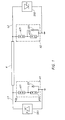
- FIG. 1 shows a high-voltage direct current transmission system with two converter stations SR 1 and SR 2, which are connected to one another via a direct current line, which consists of the overhead lines L1 and L2 and a direct current cable K.
- Voltage-limiting arrangements A1 and A2 are arranged at the two ends of the cable in order to limit the amplitude of the overvoltages, for example when a lightning overvoltage is transferred from one of the overhead lines to the cable, to a predetermined value (the protection level of the limiting arrangement).
- the limiting arrangement A1 consists of two valve arresters A11 and A12 connected in series, which are connected between the line and earth. Parallel to the valve arrester A12 is a diode valve D11, which can consist of several semiconductor diodes connected in series.
- the limiting arrangement A2 is constructed in the same way from the two valve arresters A21 and A22 and the diode valve D21.
- the transmission system operates in normal operation with a positive polarity of the line with respect to earth, ie the voltage U D in FIG. 1 is positive.
- the diodes D11 and D21 are acted on in the reverse direction, and the protection level of the limiting arrangements is equal to the sum of the protection levels of the two valve arresters connected in series.
- the diodes D11 and D21 are applied in the forward direction, so that the protection level of the limiting arrangements at this polarity is equal to the protection level of the arrester A11 and A21.
- Overvoltages of the same polarity as that of the operating voltage during normal operation are therefore limited to a higher value, and overvoltages of opposite polarity are limited to a lower value.
- the desired values for the protection levels for the two polarities can be determined by suitable selection of the response levels of the arresters.
- Figure 2 shows the field strength E in a typical DC cable (with solid insulation material) as a function of the distance r from the center of the cable.
- the radius of the conductor is denoted by r 1 and the inner radius of the jacket by r m .
- the voltage is distributed purely capacitively in the insulation material because of its short duration, which means that the field strength decreases inversely proportional to the distance from the center of the conductor.
- the resistivity is not constant, but primarily depends on the temperature and on the other hand also on the electric field strength.
- a heated conductor ie I d > 0
- a negative temperature gradient occurs between the conductor and the jacket, which increases the resistivity with regard to the distance from the center the leader gets a positive derivation.
- the stationary voltage distribution generated by the operating voltage is dependent on the size of the load current. At low loads, the distribution almost matches the purely capacitive distribution, while when the cable is fully utilized, the distribution reverses with regard to its current carrying capacity with the maximum field strength on the jacket.
- a typical cable reaches its stationary temperature distribution after a few hours or days.
- the field strength distribution at nominal load and nominal voltage in the steady state is represented by curve n h in FIG.
- a cable is normally dimensioned so that at the nominal voltage the same or approximately the same maximum field strength is obtained with both cold (curve n c ) and warm (curve n h ) cable.
- the transient voltage (difference between the total voltage and the operating voltage) is distributed capacitively between the conductor and the sheath, completely independently of the field already generated by the operating voltage.
- the resulting field is obtained by overlaying the two independent fields.
- the protection level in both directions for the limiting arrangements (A1 and A2 in FIG. 1) is the same for both polarities and that the cable operates at the nominal voltage. It is also assumed that the protection level corresponds to twice the nominal voltage.
- a positive voltage transient - i.e. one with the same polarity as the operating voltage - causes at most one additional electric field of the same size and distribution as the operating voltage field with cold cable (curve n c in Fig. 2).
- This field image is added to the operating voltage field.
- the field strength profile of the resulting field is shown in Fig. 2 by the curve for the cold cable and the curve shown for the warm cable.
- a negative transient can reach a maximum amplitude that is three times the nominal voltage and can generate a negative field strength component, the distribution of which has the same appearance as the curve n c but with three times the amplitude.
- the resulting field strength distribution is obtained by adding this (negative) component to the operating voltage-related component.
- the resulting field strength distribution for the cold cable shows the curve S- and for the warm cable the curve Sh.
- the maximum field strength with warm cable becomes considerably larger than the maximum field strength with positive transient and cold cable.
- the field strength with negative transients and warm cable is therefore decisive for the design. What has been said here applies to already known transmission systems.
- the level of protection in the transmission system according to the invention is lower for overvoltages with opposite polarity compared to the normal operating voltage. It is now assumed that the level of protection in the transmission system according to the invention for positive polarity is the same as in the example above, namely twice the operating voltage, but that it is only half as large for negative polarity, namely equal to the operating voltage.
- FIG. 3 shows an alternative embodiment of one of the voltage-limiting arrangements according to FIG. 1.
- a first valve arrester A13 is connected between line and earth and has a protection level that is adapted to transients with the same polarity as that of the operating voltage.
- a second valve arrester A14 has a lower protection level and is connected in series with a diode circuit D11 to the line. This valve arrester can therefore only respond to transients whose polarity is opposite to the operating voltage (the operating voltage is assumed to have a positive polarity with respect to earth).
- the voltage-limiting arrangements are expediently designed to be switchable for a longer polarity change.
- the limiting arrangement A1 according to FIG. 1 can be made switchable in such a way that, according to FIG. 4, a switch S11 is provided in series with the diode D11 and that a second diode D12 with the opposite forward direction is arranged in series with a second switch S12 in parallel with the arrester A12 becomes.
- a switch S11 is provided in series with the diode D11 and that a second diode D12 with the opposite forward direction is arranged in series with a second switch S12 in parallel with the arrester A12 becomes.
- voltage u D When operating with positive operating voltage.
- voltage u D is closed, the switch S11 and the switch S12 opened.
- the transmission system is expediently operated with a lower operating voltage which is adapted to the lower protection level prevailing at this polarity.
- the switch S11 is opened and the switch S12 is closed, after which the operating voltage is increased to the full value.
- the transmission system now works as before the polarity change with a higher protection level for the polarity of the operating voltage and with a lower protection level for the opposite polarity.
- the arrester circuit according to FIG. 3 can be used for the same mode of operation if, according to FIG. 5, a further diode D12 and two switches S13 and S14 are inserted.
- the maximum field strength is obtained with a transient with the same polarity as the operating voltage and with a cold cable.
- This field strength stress can be reduced in that, when the transmission system (cold cable) is started up, initially only with a reduced voltage and a reduced protection level for the transients mentioned
- the level of protection against voltages with opposite polarity to the operating voltage is not zero, but has a finite and not too small value.
- the voltage can be briefly reversed in the event of errors without switching over the arrester protection.
- short-circuit currents can be reduced more quickly and reliable arcing of possible arcs can be achieved.
- the direction of performance of the transmission can be briefly reversed, which has significant advantages in certain situations.
- the ratio between the size of the lower and the size of the higher of the two limiting levels is within a preferred range.
- This ratio should be in the range of at least 0.2 to at most 0.8.
- the transmission system shown in FIG. 1 is essentially intended for power transmission in the same direction. Because the voltage-limiting arrangements are switchable (for example, according to FIGS. 4 and 5), the transmission can be carried out in both directions, ie the full power can be transmitted in both directions. A change in the power direction then takes place by changing the polarity of the operating voltage u D. Another way of achieving the possibility of power transmission in both directions is to enable a change in the current direction while the polarity of the operating voltage remains the same. This can be done by providing the converters SR1 and SR2 with pole reversers or by designing each of the converters as a double converter.
- the operating voltage is normally positive to earth.
- the transmission system can also be constructed so that the normal operating voltage is negative with respect to earth.
- the diode circuits D11, D12 with the switches S11, S12 can be replaced by a single diode circuit provided with a pole reverser.
Landscapes
- Engineering & Computer Science (AREA)
- Power Engineering (AREA)
- Emergency Protection Circuit Devices (AREA)
- Direct Current Feeding And Distribution (AREA)
Applications Claiming Priority (2)
| Application Number | Priority Date | Filing Date | Title |
|---|---|---|---|
| SE7910716 | 1979-12-28 | ||
| SE7910716A SE445002B (sv) | 1979-12-28 | 1979-12-28 | Kraftoverforing for hogspend likstrom med spenningsbegrensande organ for begrensning av linjespenningen |
Publications (3)
| Publication Number | Publication Date |
|---|---|
| EP0031594A2 true EP0031594A2 (fr) | 1981-07-08 |
| EP0031594A3 EP0031594A3 (en) | 1981-07-15 |
| EP0031594B1 EP0031594B1 (fr) | 1983-08-10 |
Family
ID=20339659
Family Applications (1)
| Application Number | Title | Priority Date | Filing Date |
|---|---|---|---|
| EP80108227A Expired EP0031594B1 (fr) | 1979-12-28 | 1980-12-27 | Installation de transmission de courant continu à haute tension |
Country Status (6)
| Country | Link |
|---|---|
| US (1) | US4334264A (fr) |
| EP (1) | EP0031594B1 (fr) |
| JP (1) | JPS56101338A (fr) |
| CA (1) | CA1157512A (fr) |
| DE (1) | DE3064549D1 (fr) |
| SE (1) | SE445002B (fr) |
Cited By (3)
| Publication number | Priority date | Publication date | Assignee | Title |
|---|---|---|---|---|
| EP2091123A3 (fr) * | 2008-02-12 | 2017-07-05 | Rolls-Royce plc | Agencement de mise à la terre de système électrique CC et procédé d'opération de l'agencement de mise à la terre pour système électrique CC |
| NL2023297B1 (en) * | 2019-06-12 | 2021-01-21 | Univ Delft Tech | Method and system for transferring electrical power |
| WO2022083868A1 (fr) * | 2020-10-22 | 2022-04-28 | Siemens Energy Global GmbH & Co. KG | Configuration ayant une ligne de transmission à courant continu |
Families Citing this family (5)
| Publication number | Priority date | Publication date | Assignee | Title |
|---|---|---|---|---|
| US5444610A (en) * | 1993-10-22 | 1995-08-22 | Diversified Technologies, Inc. | High-power modulator |
| US6043636A (en) * | 1997-10-20 | 2000-03-28 | Diversified Technologies, Inc. | Voltage transient suppression |
| US6611443B2 (en) | 2001-05-29 | 2003-08-26 | Biversfied Technologies, Inc. | High voltage converter system |
| CN101341642B (zh) * | 2005-12-21 | 2010-12-29 | Abb技术有限公司 | 高压直流系统 |
| US20070169299A1 (en) * | 2006-01-25 | 2007-07-26 | Dragoslav Stankovic | Apparatus, system and method for scraping a surface |
Family Cites Families (5)
| Publication number | Priority date | Publication date | Assignee | Title |
|---|---|---|---|---|
| US2730667A (en) * | 1951-04-23 | 1956-01-10 | Asea Ab | Protective means for high voltage direct current transmissions |
| US2763818A (en) * | 1954-10-14 | 1956-09-18 | Westinghouse Electric Corp | Lighting arrester |
| DE1969657U (de) * | 1960-02-12 | 1967-10-05 | Siemens Ag | Ueberspannungsableiter. |
| DE1538118B1 (de) * | 1965-11-19 | 1971-02-25 | Siemens Ag | Stromversorgungsanlage zur Speisung mehrerer Gleichspannungsverbraucher mit praktisch konstanter Spannung |
| SE336021B (fr) * | 1969-10-10 | 1971-06-21 | Asea Ab |
-
1979
- 1979-12-28 SE SE7910716A patent/SE445002B/sv not_active IP Right Cessation
-
1980
- 1980-12-18 CA CA000367070A patent/CA1157512A/fr not_active Expired
- 1980-12-25 JP JP18497480A patent/JPS56101338A/ja active Pending
- 1980-12-27 DE DE8080108227T patent/DE3064549D1/de not_active Expired
- 1980-12-27 EP EP80108227A patent/EP0031594B1/fr not_active Expired
- 1980-12-29 US US06/220,489 patent/US4334264A/en not_active Expired - Lifetime
Cited By (3)
| Publication number | Priority date | Publication date | Assignee | Title |
|---|---|---|---|---|
| EP2091123A3 (fr) * | 2008-02-12 | 2017-07-05 | Rolls-Royce plc | Agencement de mise à la terre de système électrique CC et procédé d'opération de l'agencement de mise à la terre pour système électrique CC |
| NL2023297B1 (en) * | 2019-06-12 | 2021-01-21 | Univ Delft Tech | Method and system for transferring electrical power |
| WO2022083868A1 (fr) * | 2020-10-22 | 2022-04-28 | Siemens Energy Global GmbH & Co. KG | Configuration ayant une ligne de transmission à courant continu |
Also Published As
| Publication number | Publication date |
|---|---|
| SE7910716L (sv) | 1981-06-29 |
| EP0031594B1 (fr) | 1983-08-10 |
| CA1157512A (fr) | 1983-11-22 |
| US4334264A (en) | 1982-06-08 |
| JPS56101338A (en) | 1981-08-13 |
| DE3064549D1 (en) | 1983-09-15 |
| SE445002B (sv) | 1986-05-20 |
| EP0031594A3 (en) | 1981-07-15 |
Similar Documents
| Publication | Publication Date | Title |
|---|---|---|
| DE69408811T2 (de) | Gleichstrom-Hochleistungsschalter | |
| EP0116275B1 (fr) | Compensateur de puissance réactive | |
| EP3853957B1 (fr) | Commutateur électronique à protection contre les surtensions | |
| DE3225285C2 (de) | Verfahren zum Betrieb einer Hochspannungs-Gleichstrom-Übertragungsanlage mit beliebig vielen Umformerstationen | |
| DE2506021C2 (de) | Überspannungs-Schutzschaltungsanordnung für Hochleistungsthyristoren | |
| DE4117677A1 (de) | Verfahren und anordnung zum schutz von supraleitspulen | |
| DE69411651T2 (de) | Schaltvorrichtung in einem Gleichstromkreis zur Umleitung eines Stromes von einem Stromkreis in einen anderen | |
| DE2127771C3 (de) | Gleichstrom-Leistungsschalteinrichtung | |
| EP0031594B1 (fr) | Installation de transmission de courant continu à haute tension | |
| DE2208432C3 (de) | Leistungsschalteinrichtung | |
| DE2644715A1 (de) | Einrichtung zur befreiung elektrischer oder elektronischer einwegschalter von hoher verlustleistungsbeanspruchung waehrend des einschaltens und ueberhoehter sperrspannungsbeanspruchung beim ausschalten | |
| DE19702094B4 (de) | Leistungsschaltvorrichtung | |
| DE4403008A1 (de) | Stromrichteranlage mit Überspannungsschutzschaltung | |
| EP0576395A1 (fr) | Dispositif de protection pour la protection d'in dispositif électrique contre la surtension sur le réseau électrique | |
| DE3812058A1 (de) | Anordnung fuer den ueberspannungsschutz in niederspannungsanlagen | |
| DE19838109B4 (de) | Ansteuerschaltung für induktive Lasten | |
| DE2350584A1 (de) | Mit spannungsteilung arbeitende gleichstrom-leistungsschalteinrichtung | |
| DE102016223022A1 (de) | Induktiver Strombegrenzer für Gleichstromanwendungen | |
| DE69814257T3 (de) | ?berspannungsschutzeinrichtung mit parallel geschalteten Funkenstrecken jeweils mit einer Induktivitõt | |
| DE2026685B2 (de) | Verfahren und Schalteinrichtung zum Unterbrechen von Gleichstrom-Energieübertragungsnetzen | |
| CH645482A5 (de) | Gekapselte ueberspannungsableitungsvorrichtung fuer eine hochspannungsanlage. | |
| DE10221714A1 (de) | Überspannungsschutz | |
| DE2259530A1 (de) | Sicherheitseinrichtung fuer eine elektrische schaltung | |
| DE2123849A1 (de) | Verzögerungsvorrichtung | |
| DE102020121589A1 (de) | Überspannungsschutzanordnung |
Legal Events
| Date | Code | Title | Description |
|---|---|---|---|
| PUAI | Public reference made under article 153(3) epc to a published international application that has entered the european phase |
Free format text: ORIGINAL CODE: 0009012 |
|
| PUAL | Search report despatched |
Free format text: ORIGINAL CODE: 0009013 |
|
| AK | Designated contracting states |
Designated state(s): CH DE FR GB |
|
| AK | Designated contracting states |
Designated state(s): CH DE FR GB |
|
| 17P | Request for examination filed |
Effective date: 19810926 |
|
| GRAA | (expected) grant |
Free format text: ORIGINAL CODE: 0009210 |
|
| AK | Designated contracting states |
Designated state(s): CH DE FR GB LI |
|
| REF | Corresponds to: |
Ref document number: 3064549 Country of ref document: DE Date of ref document: 19830915 |
|
| ET | Fr: translation filed | ||
| PLBE | No opposition filed within time limit |
Free format text: ORIGINAL CODE: 0009261 |
|
| STAA | Information on the status of an ep patent application or granted ep patent |
Free format text: STATUS: NO OPPOSITION FILED WITHIN TIME LIMIT |
|
| 26N | No opposition filed | ||
| PGFP | Annual fee paid to national office [announced via postgrant information from national office to epo] |
Ref country code: CH Payment date: 19841221 Year of fee payment: 5 |
|
| PG25 | Lapsed in a contracting state [announced via postgrant information from national office to epo] |
Ref country code: LI Effective date: 19881231 Ref country code: CH Effective date: 19881231 |
|
| REG | Reference to a national code |
Ref country code: CH Ref legal event code: PL |
|
| PGFP | Annual fee paid to national office [announced via postgrant information from national office to epo] |
Ref country code: FR Payment date: 19961211 Year of fee payment: 17 |
|
| PGFP | Annual fee paid to national office [announced via postgrant information from national office to epo] |
Ref country code: GB Payment date: 19961218 Year of fee payment: 17 |
|
| PGFP | Annual fee paid to national office [announced via postgrant information from national office to epo] |
Ref country code: DE Payment date: 19970107 Year of fee payment: 17 |
|
| PG25 | Lapsed in a contracting state [announced via postgrant information from national office to epo] |
Ref country code: GB Free format text: LAPSE BECAUSE OF NON-PAYMENT OF DUE FEES Effective date: 19971227 |
|
| PG25 | Lapsed in a contracting state [announced via postgrant information from national office to epo] |
Ref country code: FR Free format text: THE PATENT HAS BEEN ANNULLED BY A DECISION OF A NATIONAL AUTHORITY Effective date: 19971231 |
|
| GBPC | Gb: european patent ceased through non-payment of renewal fee |
Effective date: 19971227 |
|
| PG25 | Lapsed in a contracting state [announced via postgrant information from national office to epo] |
Ref country code: DE Free format text: LAPSE BECAUSE OF NON-PAYMENT OF DUE FEES Effective date: 19980901 |
|
| REG | Reference to a national code |
Ref country code: FR Ref legal event code: ST |