EP0032102A2 - Vorrichtung zum Entgraten und Abschrägen von Löchern in perforierten Platten - Google Patents
Vorrichtung zum Entgraten und Abschrägen von Löchern in perforierten Platten Download PDFInfo
- Publication number
- EP0032102A2 EP0032102A2 EP80401894A EP80401894A EP0032102A2 EP 0032102 A2 EP0032102 A2 EP 0032102A2 EP 80401894 A EP80401894 A EP 80401894A EP 80401894 A EP80401894 A EP 80401894A EP 0032102 A2 EP0032102 A2 EP 0032102A2
- Authority
- EP
- European Patent Office
- Prior art keywords
- plate
- support
- brush
- holes
- deburring
- Prior art date
- Legal status (The legal status is an assumption and is not a legal conclusion. Google has not performed a legal analysis and makes no representation as to the accuracy of the status listed.)
- Granted
Links
- 238000006073 displacement reaction Methods 0.000 claims abstract description 16
- 230000001680 brushing effect Effects 0.000 claims abstract description 11
- 239000002184 metal Substances 0.000 claims abstract description 5
- 239000000835 fiber Substances 0.000 claims description 5
- 229910000831 Steel Inorganic materials 0.000 claims description 3
- 239000010959 steel Substances 0.000 claims description 3
- 125000006850 spacer group Chemical group 0.000 description 12
- XLYOFNOQVPJJNP-UHFFFAOYSA-N water Substances O XLYOFNOQVPJJNP-UHFFFAOYSA-N 0.000 description 7
- 230000035515 penetration Effects 0.000 description 6
- 239000012530 fluid Substances 0.000 description 5
- 238000009434 installation Methods 0.000 description 4
- 230000015572 biosynthetic process Effects 0.000 description 2
- 238000004519 manufacturing process Methods 0.000 description 2
- 238000000034 method Methods 0.000 description 2
- 230000001105 regulatory effect Effects 0.000 description 2
- 244000198134 Agave sisalana Species 0.000 description 1
- 239000004677 Nylon Substances 0.000 description 1
- 239000003082 abrasive agent Substances 0.000 description 1
- 230000001276 controlling effect Effects 0.000 description 1
- 230000007547 defect Effects 0.000 description 1
- 238000005553 drilling Methods 0.000 description 1
- 230000008030 elimination Effects 0.000 description 1
- 238000003379 elimination reaction Methods 0.000 description 1
- 239000012535 impurity Substances 0.000 description 1
- 239000007788 liquid Substances 0.000 description 1
- 238000003754 machining Methods 0.000 description 1
- 238000012423 maintenance Methods 0.000 description 1
- 239000000463 material Substances 0.000 description 1
- 238000005259 measurement Methods 0.000 description 1
- 239000002923 metal particle Substances 0.000 description 1
- 229920001778 nylon Polymers 0.000 description 1
- 235000011837 pasties Nutrition 0.000 description 1
- 230000008439 repair process Effects 0.000 description 1
- 230000001850 reproductive effect Effects 0.000 description 1
- 229920002994 synthetic fiber Polymers 0.000 description 1
- 238000009834 vaporization Methods 0.000 description 1
- 230000008016 vaporization Effects 0.000 description 1
Images

Classifications
-
- B—PERFORMING OPERATIONS; TRANSPORTING
- B24—GRINDING; POLISHING
- B24B—MACHINES, DEVICES, OR PROCESSES FOR GRINDING OR POLISHING; DRESSING OR CONDITIONING OF ABRADING SURFACES; FEEDING OF GRINDING, POLISHING, OR LAPPING AGENTS
- B24B9/00—Machines or devices designed for grinding edges or bevels on work or for removing burrs; Accessories therefor
- B24B9/002—Machines or devices designed for grinding edges or bevels on work or for removing burrs; Accessories therefor for travelling workpieces
Definitions
- the invention relates to a device for deburring and chamfering the holes of a perforated plate which comprises a set of holes of any shape machined during an operation leaving a rim of metal pushed back and sharp angles on the edges of the hole , on at least one of the faces of the plate.
- the steam generators of pressurized water nuclear reactors consist of a large envelope of generally cylindrical shape inside which is disposed a bundle of small diameter tubes tightly fixed on a tubular plate at each of their ends, these tubes having a vertical path inside the envelope of the steam generator over a great length and being bent with a certain curvature at their upper part.
- the vertical parts of the bundle tubes must be kept in position in relation to each other, the cross-sections of the tubes constituting regular networks in planes perpendicular to the axis of the exchanger.
- spacer plates are used, arranged with a certain spacing along the height of the heat exchanger, these spacer plates having holes in a network corresponding to the network of tubes.
- holes of more or less complex shapes passing through the spacer plates right through are made by conventional machining methods such as drilling, reaming or broaching.
- the holes thus machined have a rim of repelled metal and sharp angles on their edge so that it is necessary on the one hand to deb a - burer and on the other hand to chamfer the edges of these holes.
- the object of the invention is to propose a device for deburring and chamfering the holes of a perforated plate which comprises a set of holes of any shape machined during an operation leaving a rim of repelled metal and sharp angles. on the edge of the holes, on at least one of the faces of the plate, this device making it possible to carry out deburring and chamfering operations quickly and automatically.
- the support 1 is fixed thanks to a support structure 4 on the fixed frame of the installation on which is also fixed a control gateway 5 and a gateway 6 usable for repairs and maintenance of the device.
- a control console 7 of the device On the bridge 5 is arranged a control console 7 of the device.
- the support device 4 in a slightly inclined position relative to the vertical also supports two devices 9 and 10 with rollers for the support and the rotation of the spacer plate 2.
- Each of the roller support devices 9 and 10 comprises, as can be seen in FIG. 2, a geared motor 11 driving a roller 12 whose groove makes it possible to receive the edge of the spacer plate 2.
- rollers such as 14 whose axis is slightly inclined relative to the vertical, at the same inclination as the support 1 .
- the support and rotation devices 9 and 10 when the motors such as 11 are powered, can put the plate in rotation about its axis of symmetry.
- the fixed frame of the installation also carries beams 16 and 17 allowing the support and guiding of a mobile support 18 maintained in an inclined position and parallel to the plate 2.
- Motor means allow the support 18 to move in the longitudinal direction of the installation between an extreme position shown in solid lines in FIG. 1 (18a out of service position) and an extreme position represented in mixed trains in FIG. 1 (18b, position in service).
- a motor 20 driving a chain pulley over which passes a chain 21 which allows the movement in the vertical direction of the carriage 22 constituted by a frame guided by the lateral uprights of the mobile support 18.
- the movable support 18 moves parallel to the perforated plate in position on the support 1 and on the other hand the carriage also moves parallel to the perforated plate 2 in a direction perpendicular to the direction of movement of the carriage 18.
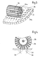
- the carriage 22 carries a motor 23 whose axis of rotation directed in the direction 25 is integral with a brush 24 with symmetry of revolution around the driven axis 25 in rotation by the motor 23.
- the brush-24 comprises a set of brushing fibers 26 arranged on the body of the brush secured to the axis 25, perpendicular to this axis 25.
- the motor 23 is mounted movably on the carriage 22 in a direction perpendicular on the one hand to the axis 25 and on the other hand to the plate 2.
- a device for moving the brush and its motor d driving in this direction allows the holes in the perforated plate to be displaced inwards, then, when the intensity of the supply current to the motor 23 reaches a certain threshold, a blockage during the entire operation of the deburring and finally a displacement in the other direction with return to the position of origin.
- the brush can be seen in the position of maximum penetration into a hole 34 in the perforated plate, the brush 24 having eliminated the burr present around the hole and caused the formation of a rounded part 30 on the edges of the hole 34 .
- the metal particles detached from the plate 27 during deburring are recovered by a vacuum cleaner 31 fixed to the carriage 22 and following all the movements of the brushing unit.
- a flexible electric power supply device 32 allows tools to be fed regardless of their position relative to the fixed support.
- the movable support 18 When it is desired to perform a deburring and chamfering operation on a spacer plate, the movable support 18 is put in the out-of-service position 18a, for the positioning of the perforated plate on the fixed support thanks to a handling means. such as an overhead crane.
- the hooking means of the traveling crane can be unhooked. After retraction of the rollers 14, the plate 2 rests on the support 1 slightly inclined relative to the vertical.
- the carriage 22 is then brought into position in front of the area of the plate 2 on which it is desired to begin the deburring operation and by displacement of the carriage 22 in the longitudinal direction of the movable support 18, the entire surface is scanned. of an area of the plate 2.
- roller devices 9 and 10 are used to cause the plate to rotate around its axis.
- Brushes of cylindrical shape comprising steel bristles with a diameter of 0.2 to 0.3 mm and with this tool it was possible to remove burrs having a section of the order of 0.05 mm2. It was also possible to achieve with this tool chamfering or shelving greater than 1 mm.
- this penetration can be controlled by the contact pressure of the brushing assembly or to a proximity measurement making it possible to know the distance between the brushing assembly and the plate.
- the main axis of this perforated plate can be, during operation, both in vertical position in horizontal position or in inclined position.
- the plate is placed in a fixed position on the support or that this plate can be moved in in rotation or translation on the mobile support to present different zones to the brushing tool.
- the device according to the invention applies not only to deburring and chamfering of spacer plates of steam generators such as the steam generators of nuclear pressurized water reactors but. also in the case of any large plate having a network of more or less regular holes.
Landscapes
- Engineering & Computer Science (AREA)
- Mechanical Engineering (AREA)
- Grinding And Polishing Of Tertiary Curved Surfaces And Surfaces With Complex Shapes (AREA)
- Finish Polishing, Edge Sharpening, And Grinding By Specific Grinding Devices (AREA)
- Polishing Bodies And Polishing Tools (AREA)
Applications Claiming Priority (2)
| Application Number | Priority Date | Filing Date | Title |
|---|---|---|---|
| FR8000138A FR2472961A1 (fr) | 1980-01-04 | 1980-01-04 | Dispositif d'ebavurage et de chanfreinage des trous d'une plaque perforee |
| FR8000138 | 1980-01-04 |
Publications (3)
| Publication Number | Publication Date |
|---|---|
| EP0032102A2 true EP0032102A2 (de) | 1981-07-15 |
| EP0032102A3 EP0032102A3 (en) | 1981-07-22 |
| EP0032102B1 EP0032102B1 (de) | 1983-12-14 |
Family
ID=9237222
Family Applications (1)
| Application Number | Title | Priority Date | Filing Date |
|---|---|---|---|
| EP80401894A Expired EP0032102B1 (de) | 1980-01-04 | 1980-12-31 | Vorrichtung zum Entgraten und Abschrägen von Löchern in perforierten Platten |
Country Status (4)
| Country | Link |
|---|---|
| EP (1) | EP0032102B1 (de) |
| DE (1) | DE3065927D1 (de) |
| ES (1) | ES8201056A1 (de) |
| FR (1) | FR2472961A1 (de) |
Cited By (3)
| Publication number | Priority date | Publication date | Assignee | Title |
|---|---|---|---|---|
| EP0465357A1 (de) * | 1990-07-04 | 1992-01-08 | Commissariat A L'energie Atomique | Gerät zum Bearbeiten von Konturen in weichem Material und automatisches Bearbeitungsverfahren mit solchem Gerät |
| EP0673714A1 (de) * | 1994-03-22 | 1995-09-27 | Framatome | Verfahren und Vorrichtung zum Entgraten und Anfasen des Randbereiches von Bohrungen durch eine Halterungsplatte für ein Rohrbündel |
| CN116352539A (zh) * | 2023-03-01 | 2023-06-30 | 武汉科技大学 | 一种用于钢丝对接焊点自动打磨装置及打磨方法 |
Family Cites Families (4)
| Publication number | Priority date | Publication date | Assignee | Title |
|---|---|---|---|---|
| US3722144A (en) * | 1971-04-06 | 1973-03-27 | Cam Ind Inc | Method and machine to de-bur commutator bars |
| GB1510086A (en) * | 1976-06-09 | 1978-05-10 | Dillinger L | Drilling or reaming machines |
| US4078905A (en) * | 1976-12-03 | 1978-03-14 | Mitsubishi Jukogyo Kabushiki Kaisha | Edge-rounding method and apparatus therefor |
| DE2658263A1 (de) * | 1976-12-22 | 1978-07-06 | Kraftwerk Union Ag | Anordnung zum nacharbeiten von kuehlrohrbohrungen an waermetauschern |
-
1980
- 1980-01-04 FR FR8000138A patent/FR2472961A1/fr active Granted
- 1980-12-29 ES ES498190A patent/ES8201056A1/es not_active Expired
- 1980-12-31 EP EP80401894A patent/EP0032102B1/de not_active Expired
- 1980-12-31 DE DE8080401894T patent/DE3065927D1/de not_active Expired
Cited By (6)
| Publication number | Priority date | Publication date | Assignee | Title |
|---|---|---|---|---|
| EP0465357A1 (de) * | 1990-07-04 | 1992-01-08 | Commissariat A L'energie Atomique | Gerät zum Bearbeiten von Konturen in weichem Material und automatisches Bearbeitungsverfahren mit solchem Gerät |
| FR2664191A1 (fr) * | 1990-07-04 | 1992-01-10 | Commissariat Energie Atomique | Appareil d'usinage de contours en materiau tendre et procede d'usinage automatique utilisant un tel appareil. |
| EP0673714A1 (de) * | 1994-03-22 | 1995-09-27 | Framatome | Verfahren und Vorrichtung zum Entgraten und Anfasen des Randbereiches von Bohrungen durch eine Halterungsplatte für ein Rohrbündel |
| FR2717726A1 (fr) * | 1994-03-22 | 1995-09-29 | Framatome Sa | Procédé et dispositif d'ébavurage et de chanfreinage de bords de trous traversant une plaque de maintien d'un faisceau de tubes. |
| US5683287A (en) * | 1994-03-22 | 1997-11-04 | Framatome | Process and device for deburring and chamfering edges of openings extending through a plate maintaining a bundle of tubes |
| CN116352539A (zh) * | 2023-03-01 | 2023-06-30 | 武汉科技大学 | 一种用于钢丝对接焊点自动打磨装置及打磨方法 |
Also Published As
| Publication number | Publication date |
|---|---|
| EP0032102A3 (en) | 1981-07-22 |
| FR2472961A1 (fr) | 1981-07-10 |
| DE3065927D1 (en) | 1984-01-19 |
| FR2472961B1 (de) | 1983-05-06 |
| ES498190A0 (es) | 1981-12-01 |
| ES8201056A1 (es) | 1981-12-01 |
| EP0032102B1 (de) | 1983-12-14 |
Similar Documents
| Publication | Publication Date | Title |
|---|---|---|
| CA1277975C (fr) | Procede pour la realisation d'un pieu dans le sol, machine de forage et dispositif pour la mise en oeuvre de ce procede | |
| EP2207637B1 (de) | Maschine zum biegen eines profils in zwei biegerichtungen und biegewerkzeug dafür | |
| WO2018087488A1 (fr) | Dispositif porte-outil pour appareil de fabrication additive selective | |
| FR2464798A1 (fr) | Machine de conditionnement pour brosser la face terminale d'un materiau metallique | |
| EP0032102B1 (de) | Vorrichtung zum Entgraten und Abschrägen von Löchern in perforierten Platten | |
| FR2695853A1 (fr) | Machine à fraiser, à surfacer et à polir à changement automatique d'outils et dispositif correspondant. | |
| FR2463660A1 (fr) | Procede et dispositif de fonctionnement d'une machine d'usinage de pieces d'ouvrage, pouvant etre equipee d'un grand nombre d'outils differents | |
| FR2499436A1 (fr) | Outil pour profiler des tubes | |
| CA2145133C (fr) | Procede et dispositif d'ebavurage et de chanfreinage de bords de trous traversant une plaque de maintien d'un faisceau de tubes | |
| CN112247791A (zh) | 一种用于金属管道焊接作业前的预处理装置 | |
| EP0038270B1 (de) | Mittel zum Unterstützen und Verschieben eines Werkzeuges an der Innenseite eines Loches | |
| EP0089907B1 (de) | Schleifmaschine für elektrische und ähnliche Kollektoren | |
| CH626148A5 (en) | Appliance for remotely repairing the tubes of a steam generator | |
| EP0598634B1 (de) | Verfahren und Vorrichtung zur Reparatur der Innenfläche eines Adapters einer Durchführung durch einen Kernreaktorbehälterdeckel | |
| FR2570970A1 (fr) | Procede d'usinage applique notamment aux augets de roues de turbine, les moyens et la machine de mise en oeuvre de ce procede. | |
| EP0082069B1 (de) | Trage- und Verschiebevorrichtung für Werkzeuge um ein Rohrbündel auf einer rohrförmigen Platte eines Dampfgenerators zu befestigen | |
| EP1345710B1 (de) | Vorrichtung und verfahren zur herstellung von anschlussstutzen in einer abgasanlage | |
| EP0778103B1 (de) | Verfahren und Vorrichtung zum serienweise elektrochemischen Ätzen von Werstücken | |
| FR2744143A1 (fr) | Meuleuse de rails | |
| EP0011318A2 (de) | Säge zum senkrechten Sägen von Marmor, Granit und sonstigen harten Steinen | |
| FR2574392A1 (fr) | Dispositif d'usinage d'un produit plat en verre | |
| EP0494808A1 (de) | Roboter | |
| EP0888230B1 (de) | Vorrichtung zum Unterhalt und zur Reparatur von Eisenbahngleisen | |
| CH681282A5 (en) | Cleaner for inner surface of pipe - has rotary brushes driven by separate electric motors to clean opposite sections of pipe surface, with brushes contained inside rotary cradle | |
| EP0304408A2 (de) | Erneuerungsmaschine |
Legal Events
| Date | Code | Title | Description |
|---|---|---|---|
| PUAI | Public reference made under article 153(3) epc to a published international application that has entered the european phase |
Free format text: ORIGINAL CODE: 0009012 |
|
| PUAL | Search report despatched |
Free format text: ORIGINAL CODE: 0009013 |
|
| AK | Designated contracting states |
Designated state(s): BE DE GB IT |
|
| AK | Designated contracting states |
Designated state(s): BE DE GB IT |
|
| 17P | Request for examination filed |
Effective date: 19810922 |
|
| ITF | It: translation for a ep patent filed | ||
| GRAA | (expected) grant |
Free format text: ORIGINAL CODE: 0009210 |
|
| AK | Designated contracting states |
Designated state(s): BE DE GB IT |
|
| REF | Corresponds to: |
Ref document number: 3065927 Country of ref document: DE Date of ref document: 19840119 |
|
| PLBE | No opposition filed within time limit |
Free format text: ORIGINAL CODE: 0009261 |
|
| STAA | Information on the status of an ep patent application or granted ep patent |
Free format text: STATUS: NO OPPOSITION FILED WITHIN TIME LIMIT |
|
| 26N | No opposition filed | ||
| ITTA | It: last paid annual fee | ||
| PGFP | Annual fee paid to national office [announced via postgrant information from national office to epo] |
Ref country code: BE Payment date: 19941205 Year of fee payment: 15 |
|
| PGFP | Annual fee paid to national office [announced via postgrant information from national office to epo] |
Ref country code: DE Payment date: 19941209 Year of fee payment: 15 |
|
| PGFP | Annual fee paid to national office [announced via postgrant information from national office to epo] |
Ref country code: GB Payment date: 19941221 Year of fee payment: 15 |
|
| PG25 | Lapsed in a contracting state [announced via postgrant information from national office to epo] |
Ref country code: GB Effective date: 19951231 Ref country code: BE Effective date: 19951231 |
|
| BERE | Be: lapsed |
Owner name: FRAMATOME Effective date: 19951231 |
|
| GBPC | Gb: european patent ceased through non-payment of renewal fee |
Effective date: 19951231 |
|
| PG25 | Lapsed in a contracting state [announced via postgrant information from national office to epo] |
Ref country code: DE Effective date: 19960903 |