EP0032205A2 - Installation commandée par touches pour la communication orale alternative ou simultanée ou par haut-parleur - Google Patents
Installation commandée par touches pour la communication orale alternative ou simultanée ou par haut-parleur Download PDFInfo
- Publication number
- EP0032205A2 EP0032205A2 EP80107740A EP80107740A EP0032205A2 EP 0032205 A2 EP0032205 A2 EP 0032205A2 EP 80107740 A EP80107740 A EP 80107740A EP 80107740 A EP80107740 A EP 80107740A EP 0032205 A2 EP0032205 A2 EP 0032205A2
- Authority
- EP
- European Patent Office
- Prior art keywords
- call
- input
- line
- connection
- transmitter
- Prior art date
- Legal status (The legal status is an assumption and is not a legal conclusion. Google has not performed a legal analysis and makes no representation as to the accuracy of the status listed.)
- Granted
Links
- 230000008878 coupling Effects 0.000 claims abstract description 4
- 238000010168 coupling process Methods 0.000 claims abstract description 4
- 238000005859 coupling reaction Methods 0.000 claims abstract description 4
- 238000004804 winding Methods 0.000 claims description 28
- 239000003990 capacitor Substances 0.000 claims description 5
- 230000000903 blocking effect Effects 0.000 claims description 2
- 238000011144 upstream manufacturing Methods 0.000 claims 2
- 238000009434 installation Methods 0.000 claims 1
- 230000006870 function Effects 0.000 description 2
- 238000010276 construction Methods 0.000 description 1
- 238000010586 diagram Methods 0.000 description 1
- 230000000694 effects Effects 0.000 description 1
- 230000015654 memory Effects 0.000 description 1
- 239000004065 semiconductor Substances 0.000 description 1
- 238000000926 separation method Methods 0.000 description 1
- 239000013589 supplement Substances 0.000 description 1
- 230000001960 triggered effect Effects 0.000 description 1
- 230000003936 working memory Effects 0.000 description 1
Images

Classifications
-
- H—ELECTRICITY
- H04—ELECTRIC COMMUNICATION TECHNIQUE
- H04M—TELEPHONIC COMMUNICATION
- H04M9/00—Arrangements for interconnection not involving centralised switching
- H04M9/002—Arrangements for interconnection not involving centralised switching with subscriber controlled access to a line, i.e. key telephone systems
- H04M9/005—Arrangements for interconnection not involving centralised switching with subscriber controlled access to a line, i.e. key telephone systems with subscriber controlled access to an exchange line
- H04M9/007—Arrangements for interconnection not involving centralised switching with subscriber controlled access to a line, i.e. key telephone systems with subscriber controlled access to an exchange line wherein the key telephone sets are star-connected to a central unit by a limited number of lines
Definitions
- the invention relates to a button-controlled exchange, intercom or loudspeaker system in which each subscriber station can connect to a predetermined number of other subscriber stations and in which the switching of the call and connection paths takes place automatically via a control center to which subscriber stations are connected via line and connecting lines are connected.
- the wiring effort in the center can be considerably reduced in a switching device for such a system and a clear and easily expandable structure of a central switching device can be obtained if a microcomputer is arranged in the center, the input / output units receiving or emitting via DC voltage signals is connected to the call and connection circuits arranged in the central office, which are arranged on three separate types of inserts, each type having at least one insert, namely line inserts on which coupling circuits are arranged, by means of which each line is connected to one of the input / output units in a direct current manner, connection slots on which
- an electronically controllable connection switching device is arranged, the control input of which is connected to one of the input / output units, and microphone units, on which a transmitter is arranged for each subscriber station, the primary winding of which is connected to a subscriber station, with a central tap of the primary winding via a the input / output units can be connected to a voltage source and the
- subscriber stations can also be connected to a switching device of the type specified above, which are not connected to the center by line and connecting lines, but also subscriber stations which are connected to the center via a four-wire line are.
- the wiring effort between the subscriber station and the control center can be considerably reduced in this way, since in the case of a subscriber station that is connected to the control center via line lines, a separate line for each line Line must be routed to the headquarters.
- the invention had for its object to provide a subscriber station which can be connected to a switching device of the type specified above and at the same time to supplement the switching device so that the connection of such a subscriber station is possible.
- At least one subscriber station is additionally connected to the control center via a four-wire line and in this subscriber station a call transmitter for transmitting coded call signals, a call keypad for actuating the call transmitter, a hearing / speaking device and a button-controlled switching device for Switching of the hearing-speaking device to speaking and for switching on and off a display device for call and busy messages are arranged and in the control center there is at least one slot of another type, namely a four-wire line slot on which a call receiver for receiving the coded Call signals and a decoder for converting the call signals to a predetermined number of lines are arranged / and each line assigned output of the decoder is connected to an input of the input / output units and to an input of an AND gate, the other input of which with this one Line-associated output of the input-output units is connected and the outputs of all the AND gates assigned to a decoder are connected to the center tap of the primary winding of the transmitter assigned to this subscriber station
- each of the subscriber stations connected to the central office via a four-wire line it is only necessary for each of the subscriber stations connected to the central office via a four-wire line to be arranged in the central office in a manner particularly adapted to the requirements of such subscriber stations.
- This insert corresponds approximately to the line inserts to which the subscriber stations connected via line lines are connected.
- a special transmitter is provided on the microphone units for each of the microphone units connected via a four-wire line.
- each slot has a certain number of inputs and outputs and is controlled by one of the input / output units.
- the program of the micro Computers is constructed in a basically known manner so that all switching functions for switching the call and S p arithmetic connections are triggered at the right time.
- circuits associated with a plurality of lines, connections, or microphone units can also be arranged on each insert.
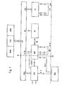
- FIG. 1 shows the basic structure of the central switching device of an alternating, counter or loudspeaker position in which there are n + 1 microphone units, of which n microphone units are connected to the central unit in a manner not shown via a total of m lines and a call station Sp0 is connected to the center via a four-wire line.
- the switching device contains a program-controlled microprocessor CPU with a RAM and a program memory ROM.
- the input-output units designated here together with EA are connected in a known manner via bus lines. How many of these input / output units are required depends on the structure of the microprocessor and the input / output units used, and on the size of the overall system.
- the input / output units EA have groups of inputs and outputs. For the sake of clarity, the individual groups of inputs and outputs are each symbolized in FIG. 1 by an output or input-output.
- the line inserts LK are connected to the input-outputs EAL, on which the coupling circuits for the lines L1 to Lm are located, which are explained in more detail below.
- connection slots VK on which the connection circuits are located, are connected to the outputs AV, and the microphone units SpK are connected to the outputs ASp, which are connected on the one hand to the microphone units Sp1 to Spn and, on the other hand, to the connection switching devices via a group symbolized by VS on the VK connection modules.
- the four-wire subscriber station SpO is connected via a first line pair VL1 to a four-wire line insert VLK and via a second line pair VL2 to one of the call station inserts SpK, which is additionally connected to the four-wire line insert VLK via a line ABM.
- the four-wire line insert VLK is connected on the one hand to the input-outputs EAVL and on the other hand to one of the outputs ASp.
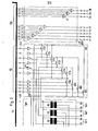
- hybrid circuits convert the operating voltage of the lines from 60V to the operating voltage of the input-output unit of 5V, and the call and busy signals emanating from each of the lines and supplied to each of the lines are sent to the separate inputs and outputs EAL of the input-output unit EA distributed.
- connection switching devices S01, S02, S03, 504, S12, S13, S14, S23, S24, S34 are arranged on the connection insert VK, which are expediently constructed as integrated semiconductor circuits.
- the control inputs of these connection switching devices receive the control signals via amplifiers P1 from corresponding outputs AV from the input / output unit EA.
- the primary windings of the transmitters U1 to U4 are connected via the speech lines a-b to the subscriber stations Spl, Sp2, Sp3 and Sp4, not shown.
- a center tap of the primary windings of the transmitters U1 to U4 is connected via an amplifier P2 to an output ASp of the input / output unit EA.
- the secondary winding of the transmitters ÜO to Ü4 is connected to earth at one end, while the other end is connected to the connection switching devices on the plug-in unit VK, via which the connection of the relevant secondary winding of the transformer to the secondary windings of the respective four other transformers can be made.
- connection switching devices S01 to S04 on the connection module VK, and the transmitter ÜO on the microphone unit module SpK, are assigned to the subscriber station SpO.
- a hearing / speaking device HS the low-frequency input of which is connected to the primary winding of the transmitter ÜO on the intercom module SpK via a transformer Ü7 and the second line pair LP2 of the four-wire line.
- a separate four-wire line slot VLK is also assigned to the subscriber station Sp0, on which a call receiver RE is arranged, which is preceded by a transmitter U5 and to which the call signals arriving via the first line pair LP1 are fed.
- a decoder DEK on four lines L17 to L20 assigned to the subscriber stations Sp1 to Sp4.
- Lines L17 to L20 are connected on the one hand to inputs EAVL of the input / output unit EA and on the other hand each to an input of an AND gate U1, U4.
- the other input of the AND gates U1, U4 is connected to the output EAVL of the input / output unit EA assigned to the respective line.
- the outputs of the AND gates U1, U4 are connected to the via an OR gate 01 and an amplifier PO Tapping the primary winding of the transformer ÜO connected.
- an output ASpo of the input / output unit EA which emits the call signals is connected to the center tap of the primary winding of the transformer UO.
- the operating voltage Ub is also supplied to the subscriber station SpO via the first line pair LP1. This takes place in that the windings of the transformers U5 and U6, to which the first line pair LP1 is connected, are separated and the separation point is bridged by capacitors C1 and C2. The supply voltage is fed to the two electrodes of the capacitor C1 and discharged to the two electrodes of the capacitor C2.
- the winding of the transformer U7 connected to the second line pair LP2 has a center tap which can be connected via a relay contact a1 to a display device LA for a call notification or a display device LB for a busy message.
- the relay contact a1 is controlled via a relay A which can be actuated from the keypad TA1.
- This relay A has a further relay contact a2, by means of which the hearing / speaking device is switched from listening to speaking.
- a call message is given via the output for call message ASpo, the OR gate 01, the amplifier PO and the second line pair LP2 and the display device LA indicates this.
- the hearing-speaking device HS is switched on and the call keypad TA1 and the relay A are blocked via the blocking input SRS on the call transmitter RS, so that at this moment no call can originate from Sp0.
- the corresponding key of the keypad TA 1 is pressed, which on the one hand actuates the relay A and on the other hand the corresponding call signal to the input EAVL and the one input of the AND -Gatters U1 is supplied. If the other subscriber station is free, the connection is switched through in the manner described analogously by means of one of the switching devices S01 to S04 via the transmitter ÜO and one of the transmitters Ü1 to Ü4. If the other subscriber station is busy, a busy signal emitted by the input / output unit EA via the output EAVL is present at the other input of the AND gate U1.
- the keys of the keypad TA1 on the microphone unit Sp0 therefore have the same function as the line keys of the other microphone units Sp1 to Sp4. They are call buttons and talk buttons at the same time. A possible busy status of a called station can be recognized immediately after pressing the corresponding key.
- the internal processor After each change in the entire system, the internal processor receives the microprocessor CPU Line entry education updated. As long as no further change occurs, all line inputs are queried continuously, but the outputs are not influenced.
Landscapes
- Engineering & Computer Science (AREA)
- Signal Processing (AREA)
- Interconnected Communication Systems, Intercoms, And Interphones (AREA)
- Selective Calling Equipment (AREA)
- Near-Field Transmission Systems (AREA)
- Mobile Radio Communication Systems (AREA)
Priority Applications (1)
| Application Number | Priority Date | Filing Date | Title |
|---|---|---|---|
| AT80107740T ATE3933T1 (de) | 1980-01-11 | 1980-12-09 | Tastengesteuerte wechsel-, gegen- oder lautsprechanlage. |
Applications Claiming Priority (2)
| Application Number | Priority Date | Filing Date | Title |
|---|---|---|---|
| DE3000858A DE3000858C2 (de) | 1980-01-11 | 1980-01-11 | Tastengesteuerte Wechsel-, Gegen- oder Lautsprechanlage |
| DE3000858 | 1980-01-11 |
Publications (3)
| Publication Number | Publication Date |
|---|---|
| EP0032205A2 true EP0032205A2 (fr) | 1981-07-22 |
| EP0032205A3 EP0032205A3 (en) | 1982-02-10 |
| EP0032205B1 EP0032205B1 (fr) | 1983-06-22 |
Family
ID=6091870
Family Applications (1)
| Application Number | Title | Priority Date | Filing Date |
|---|---|---|---|
| EP80107740A Expired EP0032205B1 (fr) | 1980-01-11 | 1980-12-09 | Installation commandée par touches pour la communication orale alternative ou simultanée ou par haut-parleur |
Country Status (3)
| Country | Link |
|---|---|
| EP (1) | EP0032205B1 (fr) |
| AT (1) | ATE3933T1 (fr) |
| DE (1) | DE3000858C2 (fr) |
Cited By (2)
| Publication number | Priority date | Publication date | Assignee | Title |
|---|---|---|---|---|
| EP0333051A3 (fr) * | 1988-03-15 | 1991-11-06 | INDUSTRONIC INDUSTRIE-ELECTRONIC GMBH & CO. KG | Dispositif de commutation librement programmable pour un central d'intercommunication à haut-parleurs |
| EP0649241A1 (fr) * | 1993-10-13 | 1995-04-19 | Neumann Elektronik GmbH | Dispositif pour transmettre des signaux d'appel et des signaux d'état d'occupation d'installations téléphoniques à lignes multiples pour la communication orale alternative ou simultanée par haut-parleur pour une ligne bifilaire grande distance |
Families Citing this family (4)
| Publication number | Priority date | Publication date | Assignee | Title |
|---|---|---|---|---|
| DE3214656C2 (de) * | 1982-04-21 | 1985-02-14 | ANT Nachrichtentechnik GmbH, 7150 Backnang | Steuereinrichtung für eine Sprechanlage |
| DE3214657C2 (de) * | 1982-04-21 | 1985-07-04 | ANT Nachrichtentechnik GmbH, 7150 Backnang | Einrichtung für die Sprach- und/oder Datenvermittlung und -übertragung |
| DE4107593C1 (fr) * | 1991-03-09 | 1992-05-21 | Fraunhofer-Gesellschaft Zur Foerderung Der Angewandten Forschung Ev, 8000 Muenchen, De | |
| DE4107591C1 (fr) * | 1991-03-09 | 1992-03-05 | Fraunhofer-Gesellschaft Zur Foerderung Der Angewandten Forschung Ev, 8000 Muenchen, De |
Family Cites Families (9)
| Publication number | Priority date | Publication date | Assignee | Title |
|---|---|---|---|---|
| DE764327C (de) * | 1938-12-31 | 1951-11-08 | Aeg | Kommando-Wechselsprech-Lautsprecheranlage |
| DE1152447B (de) * | 1960-03-10 | 1963-08-08 | Neumann Elektronik Gmbh | Wechsel-Lautsprechanlage mit tongesteuerten Verbindungswegen |
| DE1115306B (de) * | 1960-05-06 | 1961-10-19 | Neumann Elektronik Gmbh | Zentrale Pruefeinrichtung fuer Lautsprech-Verstaendigungsanlagen mit B-Verstaerkern |
| DE1171019B (de) * | 1962-07-26 | 1964-05-27 | Licentia Gmbh | Wechselsprechanlage |
| DE1224372B (de) * | 1964-10-29 | 1966-09-08 | Telefunken Patent | Steuereinrichtung fuer eine Wechselsprechanlage |
| DE2422806C3 (de) * | 1974-05-10 | 1985-08-29 | Neumann Elektronik GmbH, 4330 Mülheim | Einrichtung zur Konzentration der Linienwahlmittel in einer tastengesteuerten Sprechanlage |
| DE2837950C2 (de) * | 1978-08-31 | 1986-11-13 | Neumann Elektronik GmbH, 4330 Mülheim | Vermittlungseinrichtung für eine tastengesteuerte Wechsel-, Gegen- oder Lautsprechanlage |
| US4327256A (en) * | 1979-05-04 | 1982-04-27 | The General Electric Company Limited | Telephone system |
| NL7907134A (nl) * | 1979-09-25 | 1981-03-27 | Ericsson Telefon Mij | Telefooninstallatie van de als sterpuntinstallatie aangeduide soort. |
-
1980
- 1980-01-11 DE DE3000858A patent/DE3000858C2/de not_active Expired
- 1980-12-09 EP EP80107740A patent/EP0032205B1/fr not_active Expired
- 1980-12-09 AT AT80107740T patent/ATE3933T1/de not_active IP Right Cessation
Cited By (2)
| Publication number | Priority date | Publication date | Assignee | Title |
|---|---|---|---|---|
| EP0333051A3 (fr) * | 1988-03-15 | 1991-11-06 | INDUSTRONIC INDUSTRIE-ELECTRONIC GMBH & CO. KG | Dispositif de commutation librement programmable pour un central d'intercommunication à haut-parleurs |
| EP0649241A1 (fr) * | 1993-10-13 | 1995-04-19 | Neumann Elektronik GmbH | Dispositif pour transmettre des signaux d'appel et des signaux d'état d'occupation d'installations téléphoniques à lignes multiples pour la communication orale alternative ou simultanée par haut-parleur pour une ligne bifilaire grande distance |
Also Published As
| Publication number | Publication date |
|---|---|
| EP0032205B1 (fr) | 1983-06-22 |
| ATE3933T1 (de) | 1983-07-15 |
| DE3000858C2 (de) | 1986-11-13 |
| DE3000858B1 (de) | 1981-06-04 |
| EP0032205A3 (en) | 1982-02-10 |
Similar Documents
| Publication | Publication Date | Title |
|---|---|---|
| EP2985988A1 (fr) | Reseau intercom et poste telephonique | |
| DE2008284A1 (de) | Schaltungsanordnung zur koordinierten Herstellung von Sprech- und Videoverbindungen über selbständige Vermittlungsanlagen | |
| DE69124217T2 (de) | Verteilte Telefonkonferenz-Kontrolleinrichtung | |
| DE19526484A1 (de) | Verfahren, Kommunikationssystem und Konferenzeinheit zur Durchführung von Konferenzen | |
| EP0032205B1 (fr) | Installation commandée par touches pour la communication orale alternative ou simultanée ou par haut-parleur | |
| DE1203319B (de) | Schaltungsanordnung fuer die Wahlaufnahme-einrichtungen einer Fernsprechvermittlungsanlage | |
| EP1246150A2 (fr) | Système d'alarme d'incendie | |
| DE2837950C2 (de) | Vermittlungseinrichtung für eine tastengesteuerte Wechsel-, Gegen- oder Lautsprechanlage | |
| DE2331259A1 (de) | Schaltungsanordnung zur anrufkonzentrierung in fernmelde- insbesondere fernsprechanlagen | |
| DE2434321C3 (de) | Schaltungsanordnung für tastengesteuerte Wechselsprech-, Gegensprech- oder Lautsprecheranlagen | |
| DE2545515C3 (de) | Gegen- oder Wechselsprechanlage | |
| EP0360056B1 (fr) | Dispositif pour des centraux de télécommunications, spécialement pour les centraux téléphoniques, qui ont des circuits alimentés par une tension de service et une tension auxiliaire | |
| DE2124673C3 (de) | Schaltungsanordnung zur Übertragung von Nachrichtenverbindungen zugehörigen, insbesondere durch Schaltkennzeichen gebildeten Datensignalen, über eine PCM-Übertragungsstrecke | |
| EP0649241A1 (fr) | Dispositif pour transmettre des signaux d'appel et des signaux d'état d'occupation d'installations téléphoniques à lignes multiples pour la communication orale alternative ou simultanée par haut-parleur pour une ligne bifilaire grande distance | |
| DE3214657A1 (de) | Einrichtung fuer die sprach- und/oder datenvermittlung und -uebertragung | |
| DE2251827C3 (de) | Schaltungsanordnung zur Anschaltung einer von mehreren Teilnehmerstellen an eine einzige Anschlußleitung | |
| DE2057571C3 (de) | Schaltungsanordnung für Fernmeldeanlagen, insbesondere Fernsprechvermittlungsanlagen, mit individuellen und zentralen Geräten | |
| DE2158753C3 (de) | Schaltungsanordnung zum Aufbau von Verbindungen zwischen einer elektromechanischen Vermittlungsstelle und einer elektronisch gesteuerten Vermittlungsstelle | |
| EP0024725A1 (fr) | Circuit pour le raccordement de tables d'opératrices à un central téléphonique à multiplexage temporel à plusieurs étages | |
| DD233028A5 (de) | Dolmetscheranlage | |
| DE3223325A1 (de) | Schaltungsanordnung zur herstellung von konferenzverbindungen zwischen aktiv und passiv an der konferenz beteiligten teilnehmern | |
| DE2145680C3 (de) | Schnellrufeinrichtung für Nebenstellenanlagen | |
| DE3347609A1 (de) | Kommunikations- und ueberwachungssystem fuer verkehrstechnik | |
| DE2749643C3 (de) | Schaltungsanordnung für Fernsprechnebenstellenanlagen zur Einzelkennzeichnung von besonderen Anrufen an der Abfragestelle | |
| DE2366014C3 (de) | Bedienungsgerät zum wahlweisen Anschluß an eine Ringschleifenanlage |
Legal Events
| Date | Code | Title | Description |
|---|---|---|---|
| PUAI | Public reference made under article 153(3) epc to a published international application that has entered the european phase |
Free format text: ORIGINAL CODE: 0009012 |
|
| AK | Designated contracting states |
Designated state(s): AT BE CH GB NL SE |
|
| PUAL | Search report despatched |
Free format text: ORIGINAL CODE: 0009013 |
|
| AK | Designated contracting states |
Designated state(s): AT BE CH GB NL SE |
|
| 17P | Request for examination filed |
Effective date: 19820108 |
|
| GRAA | (expected) grant |
Free format text: ORIGINAL CODE: 0009210 |
|
| AK | Designated contracting states |
Designated state(s): AT BE CH GB LI NL SE |
|
| REF | Corresponds to: |
Ref document number: 3933 Country of ref document: AT Date of ref document: 19830715 Kind code of ref document: T |
|
| PLBI | Opposition filed |
Free format text: ORIGINAL CODE: 0009260 |
|
| PLBI | Opposition filed |
Free format text: ORIGINAL CODE: 0009260 |
|
| 26 | Opposition filed |
Opponent name: ANT NACHRICHTENTECHNIK GMBH Effective date: 19840317 |
|
| 26 | Opposition filed |
Opponent name: INDUSTRONIC INDUSTRIE-ELECTRONIC GMBH & CO. KG Effective date: 19840321 |
|
| PLBN | Opposition rejected |
Free format text: ORIGINAL CODE: 0009273 |
|
| STAA | Information on the status of an ep patent application or granted ep patent |
Free format text: STATUS: OPPOSITION REJECTED |
|
| 27O | Opposition rejected |
Effective date: 19870515 |
|
| NLR2 | Nl: decision of opposition | ||
| REG | Reference to a national code |
Ref country code: GB Ref legal event code: 746 Effective date: 19930203 |
|
| EAL | Se: european patent in force in sweden |
Ref document number: 80107740.5 |
|
| PGFP | Annual fee paid to national office [announced via postgrant information from national office to epo] |
Ref country code: BE Payment date: 19951011 Year of fee payment: 16 |
|
| PGFP | Annual fee paid to national office [announced via postgrant information from national office to epo] |
Ref country code: SE Payment date: 19951113 Year of fee payment: 16 |
|
| PGFP | Annual fee paid to national office [announced via postgrant information from national office to epo] |
Ref country code: GB Payment date: 19951129 Year of fee payment: 16 |
|
| PGFP | Annual fee paid to national office [announced via postgrant information from national office to epo] |
Ref country code: AT Payment date: 19951214 Year of fee payment: 16 |
|
| PGFP | Annual fee paid to national office [announced via postgrant information from national office to epo] |
Ref country code: NL Payment date: 19951230 Year of fee payment: 16 |
|
| PGFP | Annual fee paid to national office [announced via postgrant information from national office to epo] |
Ref country code: CH Payment date: 19960103 Year of fee payment: 16 |
|
| PG25 | Lapsed in a contracting state [announced via postgrant information from national office to epo] |
Ref country code: GB Effective date: 19961209 Ref country code: AT Effective date: 19961209 |
|
| PG25 | Lapsed in a contracting state [announced via postgrant information from national office to epo] |
Ref country code: SE Effective date: 19961210 |
|
| PG25 | Lapsed in a contracting state [announced via postgrant information from national office to epo] |
Ref country code: LI Effective date: 19961231 Ref country code: CH Effective date: 19961231 Ref country code: BE Effective date: 19961231 |
|
| BERE | Be: lapsed |
Owner name: NEUMANN ELEKTRONIK G.M.B.H. Effective date: 19961231 |
|
| PG25 | Lapsed in a contracting state [announced via postgrant information from national office to epo] |
Ref country code: NL Effective date: 19970701 |
|
| GBPC | Gb: european patent ceased through non-payment of renewal fee |
Effective date: 19961209 |
|
| REG | Reference to a national code |
Ref country code: CH Ref legal event code: PL |
|
| NLV4 | Nl: lapsed or anulled due to non-payment of the annual fee |
Effective date: 19970701 |
|
| EUG | Se: european patent has lapsed |
Ref document number: 80107740.5 |