EP0032206A1 - Verfahren zum pneumatischen Einspritzen dosierter Mengen pulverförmingen Guts in einen unter veränderlichem Druck stehenden Behälter - Google Patents
Verfahren zum pneumatischen Einspritzen dosierter Mengen pulverförmingen Guts in einen unter veränderlichem Druck stehenden Behälter Download PDFInfo
- Publication number
- EP0032206A1 EP0032206A1 EP80107798A EP80107798A EP0032206A1 EP 0032206 A1 EP0032206 A1 EP 0032206A1 EP 80107798 A EP80107798 A EP 80107798A EP 80107798 A EP80107798 A EP 80107798A EP 0032206 A1 EP0032206 A1 EP 0032206A1
- Authority
- EP
- European Patent Office
- Prior art keywords
- pressure
- transport path
- propulsion
- booster
- enclosure
- Prior art date
- Legal status (The legal status is an assumption and is not a legal conclusion. Google has not performed a legal analysis and makes no representation as to the accuracy of the status listed.)
- Withdrawn
Links
- 238000000034 method Methods 0.000 title claims description 20
- 239000007787 solid Substances 0.000 title description 2
- 239000012530 fluid Substances 0.000 claims abstract description 24
- 238000002347 injection Methods 0.000 claims abstract description 15
- 239000007924 injection Substances 0.000 claims abstract description 15
- 239000000463 material Substances 0.000 claims description 26
- 239000003245 coal Substances 0.000 claims description 20
- 238000009434 installation Methods 0.000 claims description 19
- 239000004449 solid propellant Substances 0.000 claims description 8
- 239000000446 fuel Substances 0.000 claims description 7
- 239000000843 powder Substances 0.000 claims description 7
- 239000003380 propellant Substances 0.000 claims description 4
- 230000001413 cellular effect Effects 0.000 claims description 3
- 238000012937 correction Methods 0.000 claims description 3
- 238000010438 heat treatment Methods 0.000 claims description 2
- 239000003077 lignite Substances 0.000 claims 1
- 238000012544 monitoring process Methods 0.000 claims 1
- OKTJSMMVPCPJKN-UHFFFAOYSA-N Carbon Chemical compound [C] OKTJSMMVPCPJKN-UHFFFAOYSA-N 0.000 abstract description 12
- 239000002817 coal dust Substances 0.000 abstract description 9
- 229910052799 carbon Inorganic materials 0.000 abstract description 8
- 239000000428 dust Substances 0.000 abstract description 5
- 230000015572 biosynthetic process Effects 0.000 abstract description 3
- 239000000243 solution Substances 0.000 description 4
- 239000000969 carrier Substances 0.000 description 3
- 230000001105 regulatory effect Effects 0.000 description 2
- UAEPNZWRGJTJPN-UHFFFAOYSA-N CC1CCCCC1 Chemical compound CC1CCCCC1 UAEPNZWRGJTJPN-UHFFFAOYSA-N 0.000 description 1
- 229910000805 Pig iron Inorganic materials 0.000 description 1
- 238000013459 approach Methods 0.000 description 1
- 239000003610 charcoal Substances 0.000 description 1
- 238000010586 diagram Methods 0.000 description 1
- 230000009977 dual effect Effects 0.000 description 1
- 230000000694 effects Effects 0.000 description 1
- 238000013213 extrapolation Methods 0.000 description 1
- 238000012886 linear function Methods 0.000 description 1
- 238000005259 measurement Methods 0.000 description 1
- 239000000203 mixture Substances 0.000 description 1
- 238000012806 monitoring device Methods 0.000 description 1
- 239000003209 petroleum derivative Substances 0.000 description 1
- 230000003068 static effect Effects 0.000 description 1
- 239000000126 substance Substances 0.000 description 1
- 238000011144 upstream manufacturing Methods 0.000 description 1
- 239000002699 waste material Substances 0.000 description 1
Images


Classifications
-
- C—CHEMISTRY; METALLURGY
- C21—METALLURGY OF IRON
- C21B—MANUFACTURE OF IRON OR STEEL
- C21B5/00—Making pig-iron in the blast furnace
- C21B5/001—Injecting additional fuel or reducing agents
- C21B5/003—Injection of pulverulent coal
-
- B—PERFORMING OPERATIONS; TRANSPORTING
- B65—CONVEYING; PACKING; STORING; HANDLING THIN OR FILAMENTARY MATERIAL
- B65G—TRANSPORT OR STORAGE DEVICES, e.g. CONVEYORS FOR LOADING OR TIPPING, SHOP CONVEYOR SYSTEMS OR PNEUMATIC TUBE CONVEYORS
- B65G53/00—Conveying materials in bulk through troughs, pipes or tubes by floating the materials or by flow of gas, liquid or foam
- B65G53/34—Details
- B65G53/66—Use of indicator or control devices, e.g. for controlling gas pressure, for controlling proportions of material and gas, for indicating or preventing jamming of material
Definitions
- the total amount of cold air mixed with the hot wind to have a constant temperature does not change, the difference being that part of the mixing, instead of being carried out in the mixing station, is carried out at the level injection of solid fuel into the blower or into the nozzles.
- Another solution would be to control the speed of the booster as a function of the pressure variations inside the oven, these variations being known and constantly monitored.
- this solution is linked to another problem, since the pressure drop in the pneumatic transport path is not only a function of the quantity of fuel per unit of propulsion fluid, but also of the pressure inside the oven and this in a non-linear way. Consequently, a control of the speed of the booster to have the minimum pressure necessary for the injection of fuel into the furnace in the pneumatic transport channel is, above all because of the non-linearity of the relationship between the pressure drop and the pressure fluctuations inside the oven, extremely complicated if not technically impossible.
- the purpose of the present invention is to provide a new process of the kind described in the preamble which allows, by means of simple regulation of various parameters, to carry out the injection of solid fuel under optimal conditions and corresponding to a minimum of energy. necessary to achieve it.
- Another objective of the invention is an installation for the implementation of this process, as well as its application to the injection of solid fuels into a tank furnace.
- the invention provides a method of injecting metered quantities of pulverulent materials by pneumatic route into an enclosure located under variable pressure through a pneumatic transport path supplied with pulverulent material and pressurized propulsion fluid injected at through a booster, characterized in that the quantity of propulsion fluid is varied as a function of pressure fluctuations in the enclosure, respecting the double condition that, for a given pressure in the enclosure, the quantity of propulsion fluid is minimal but sufficient to ensure a propulsion speed without risk of blockage, in that the pressure variations in the pneumatic transport track are continuously monitored and in that the quantity of pulverulent material introduced into this transport path is adjusted so that the pressure drop along the transport path is maintained at a determined value.
- the variation in the quantity of propulsion fluid as a function of pressure fluctuations in the enclosure is carried out according to a linear relationship.
- This regulation of the quantity of propellant means that the pressure drop in the pneumatic transport path is constant for a given quantity of pulverulent material and this over the whole range of pressure variations at the inside the enclosure.
- the relationship between the pressure required in the pneumatic conveying path and the pressure inside the oven has been linearized. This allows simple regulation of the booster by adapting its speed to variations in pressure in the oven.
- This regulation also causing a linear relationship between the pressure drop in the transport path and the total hourly quantity of pulverulent material to be injected, the introduction of pulverulent material into the transport path is regulated as a function of possible variations in falls of pressure in the transport path so that these pressure drops are maintained at the value corresponding to the hourly quantity of pulverulent material to be injected.
- the invention also relates to an installation comprising a device for introducing powdery material into a pneumatic transport path connected to a booster to supply the transport path with propulsion fluid, characterized by an automatic valve disposed between the booster and the device introduction of pulverulent material and actuated by a control device according to the momentary pressure inside of the enclosure.
- the introduction device is preferably an airlock with a cellular rotor, the speed of rotation of which is controlled as a function of pressure variations in the transport path.
- the invention also proposes the application of this method and of this installation to a shaft furnace in which the pulverulent material is a solid fuel, characterized in that a pneumatic transport path is provided with an automatic valve and an airlock with honeycomb rotor for each pair of nozzles.
- the invention will be described, by way of illustration, with reference to its application in an installation as proposed by the Luxembourg patent 81,519.
- the propulsion fluid will be air cold, while the pulverulent substances are coal powder.
- the pressure vessel will be a blast furnace. It is however obvious that the invention is also applicable for other propulsion fluids, for other pulverulent materials and for other pressure vessels.
- Figure 1 illustrates a series of curves showing the minimum pressure necessary downstream of the booster to inject the fluid into the blast furnace in which there is a back pressure indicated by "P c " and plotted on the abscissa on the graph.
- the pressures have been represented, both on the y-axis and on the x-axis, in bars.
- the curves were calculated for a transport line with a length of one hundred meters and for a quantity of propelling air of three hundred and fifty cubic meters per hour.
- the straight line at 45 ° represents the static conditions corresponding to equilibrium, that is to say for which there is no circulation in the pneumatic transport track.
- the parameter of the different curves is the density ⁇ representing the number of kilos of coal dust per kilo of propulsion air per hour.
- the lower curve for which ⁇ is equal to zero, corresponds to the injection of pure air, while as the carbon density increases, the curves go up on the ordinate.
- the pressure drop in the pneumatic transport path i.e. the pressure difference ⁇ P between a point immediately downstream of the booster and the injection point in the furnace, corresponds to the difference in ordinate between a determined point of one of the curves and the corresponding point on the right at 45 ° having the same abscissa. Since the curves are not parallel, this pressure difference ⁇ P varies not only from one curve to another, but also as a function of the absolute and momentary value of the pressure P inside the oven.
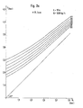
- FIG. 2a illustrates a family of curves similar to those of FIG. 1 and shows the relationship between the pressure P immediately downstream of the booster and the backpressure P inside the enclosure, with as parameter the quantity of air from propulsion in cubic meters per hour.
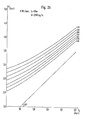
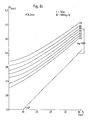
- FIGS. 2a, 2b and 2c A linear relationship between the pressure P and the back pressure P would be represented in FIGS. 2a, 2b and 2c by a straight line and one could imagine such a straight line parallel to the straight line shown at 45 °. Such an imaginary straight line would therefore correspond to a constant pressure drop ⁇ P over the entire length of the transport pipe and for all the values of P c . Given that such an imaginary straight line intersects the different curves represented in FIGS. 2a, 2b and 2c, curves characterized by the variable parameter of the quantity of air, one could imagine that by varying, in an appropriate manner, the quantity of air injected into the pipe to propel the coal dust, we would obtain a linear relationship between the pressure P and the back pressure P c and which can be represented by the imaginary lines of which question above.
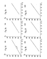
- the graphs in FIGS. 3a to 3f have been established for a minimum speed of 15 meters per second corresponding to the speed necessary for circulation in the transport track and to avoid the risk of the formation of traffic jams.
- the graph in FIG. 4 therefore makes it possible to know for each quantity of coal dust to be injected the slope of the straight line representing the variation in the quantity of air as a function of the back pressure P as shown in FIGS. 3a to 3f.
- the amount of air is therefore clearly determined for each back pressure and for each amount of carbon injected.
- FIG. 5 shows the pressure drop for each value of quantity of coal, in other words, the pressure necessary downstream of the booster to inject a given quantity of coal into the furnace.
- ⁇ P 0.8 bars, that is to say that the pressure P must be 0.8 bars higher than that prevailing in the oven.
- the graph in FIG. 5 is also used to ensure self-regulation so as to fulfill this condition. For this purpose, it suffices to measure the pressure at any two points on the pneumatic transport track and to monitor the pressure difference between these two points. If a fluctuation occurs, that is to say a momentary deviation from the set value, the quantity Q of carbon powder can be slightly varied to restore the situation.
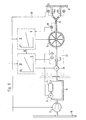
- a booster 12 is intended to send the air from the pipe 10 in sufficient quantities and at the pressure P necessary to propel the coal powder.
- a cooler immediately downstream of the booster to compensate for the heating of the air occurring in the booster.
- This has also been incorporated into the installation of FIG. 6 and is indicated by the reference 14.
- this cooler is located in parallel on the pressurized air line 18 and the quantity of air passing through this cooler 14 is controlled by means of an automatic valve 16 adjusted as a function of the temperature of the propelling air downstream in the pipe. If the temperature of the propelling air is too high, the valve allows more air to pass through the cooler 14.
- an automatic valve 20 intended to regulate the total flow rate of the propelling air
- a monitoring device 22 intended to detect the effective quantity of the air circulating in the pipe as well as its pressure and its temperature and finally an airlock with honeycomb rotor 24 through which coal powder is admitted.
- the installation shown in FIG. 6 makes it possible to supply two wind carriers or nozzles at the same time and, for this purpose, the pipe is subdivided downstream of the airlock 24 into two branches 18a and 18b, which make it possible to inject the dust of coal through the two blast holders in the shaft furnace.
- an airlock 24 is provided with auxiliary equipment, which is represented diagrammatically by the dotted sub-divisions of the pipe 18 between the cooler 14 and the automatic valve 20.
- Reference 26 schematically represents the information concerning the back pressure P inside the furnace 8 and the fluctuations of this pressure. This information is used to control the booster 12, that is to say for regulating its speed of rotation linearly, as a function of P while respecting the pressure drop in accordance with the graph in FIG. 5.
- Information 26 is also used for a regulation device represented by the reference III and establishing a relation in accordance with FIGS. 3 for the automatic control of the opening of the valve 20 as a function of the back pressure P.
- the quantity of air circulating in the pipe 18 is not only a function of the valve 20, but also of the pressure and the temperature.
- the graphical and mathematical explanations above were made for normal quantities or "standard" represented by Q N.
- the relation between the normal quantity of air Q N and the quantity actually circulating in the pipe 10 Q is represented by the following two dual equations: Consequently, to ensure the correct position of the valve and allow the desired quantity Qeff of air to pass, a correction of Q N established by the regulation device III is carried out by bringing into play the absolute temperature and the pressure measured by the control device. 22 and according to the above relation.
- the airlock rotor airlock 24 is directed by a control device represented by V and operating according to the graphs of FIG. 5.
- a device 28 for detecting the pressure difference between two points any. Knowing the total pressure drop for a determined quantity of carbon to be injected, we also know the corresponding ⁇ P measured by the device 28 between these two arbitrary points and any fluctuation or deviation from the set value is transmitted by this device 28 to the command V to increase or decrease through the airlock 24 the quantity Q of coal according to FIG. 5 and thus restoring the necessary ⁇ P.
- a deflector 30 At the location of the subdivision of the pipe 18, to form the branches 18a and 18b, it is advantageous to provide a deflector 30 to control an equal distribution of the quantity of coal between the two branches 18a and 18b. To this end, it is possible to measure the pressure drops ⁇ P along each of the two branches 18a and 18b and, by comparing the results of these measurements, use these variations for an automatic control of the position of the deflector 30.
Landscapes
- Engineering & Computer Science (AREA)
- Chemical & Material Sciences (AREA)
- Mechanical Engineering (AREA)
- Manufacturing & Machinery (AREA)
- Materials Engineering (AREA)
- Metallurgy (AREA)
- Organic Chemistry (AREA)
- Air Transport Of Granular Materials (AREA)
- Manufacture Of Iron (AREA)
- Blast Furnaces (AREA)
Applications Claiming Priority (2)
| Application Number | Priority Date | Filing Date | Title |
|---|---|---|---|
| LU82036 | 1979-12-27 | ||
| LU82036A LU82036A1 (fr) | 1979-12-27 | 1979-12-27 | Procede et installation d'injection de quantites dosees de matieres pulverulentes par voie pneumatique dans une enceinte se trouvant sous pression variable et application a un four a cuve |
Publications (1)
| Publication Number | Publication Date |
|---|---|
| EP0032206A1 true EP0032206A1 (de) | 1981-07-22 |
Family
ID=19729316
Family Applications (1)
| Application Number | Title | Priority Date | Filing Date |
|---|---|---|---|
| EP80107798A Withdrawn EP0032206A1 (de) | 1979-12-27 | 1980-12-11 | Verfahren zum pneumatischen Einspritzen dosierter Mengen pulverförmingen Guts in einen unter veränderlichem Druck stehenden Behälter |
Country Status (11)
| Country | Link |
|---|---|
| US (1) | US4368678A (de) |
| EP (1) | EP0032206A1 (de) |
| JP (1) | JPS5698408A (de) |
| AR (1) | AR227295A1 (de) |
| AU (1) | AU6453980A (de) |
| BR (1) | BR8008576A (de) |
| CA (1) | CA1154251A (de) |
| ES (1) | ES497279A0 (de) |
| LU (1) | LU82036A1 (de) |
| PL (1) | PL228695A1 (de) |
| ZA (1) | ZA807243B (de) |
Cited By (4)
| Publication number | Priority date | Publication date | Assignee | Title |
|---|---|---|---|---|
| FR2511986A1 (fr) * | 1981-08-28 | 1983-03-04 | Waeschle Maschf Gmbh | Procede pour le dosage de matieres en vrac transportees pneumatiquement |
| EP0077919A1 (de) * | 1981-10-02 | 1983-05-04 | Paul Wurth S.A. | Verfahren zum pneumatischen Einbringen dosierter Mengen pulverförmiger Stoffe in einen unter veränderlichem Druck stehenden Behälter und die Anwendung dieses Verfahrens auf Schachtöfen |
| FR2530015A1 (fr) * | 1982-07-07 | 1984-01-13 | Kloeckner Stahlforschung | Procede et dispositif pour mesurer et/ou regler un courant massique de particules solides |
| EP0190592A1 (de) * | 1985-01-24 | 1986-08-13 | Paul Wurth S.A. | Verfahren und Vorrichtung zum pneumatischen Einbringen dosierter Mengen pulverförmiger Stoffe in einem unter Druck stehenden Behälter und die Anwendung dieses Verfahrens auf Schachtöfen |
Families Citing this family (16)
| Publication number | Priority date | Publication date | Assignee | Title |
|---|---|---|---|---|
| US4480560A (en) * | 1983-12-09 | 1984-11-06 | International Coal Refining Company | Pneumatic conveying of pulverized solvent refined coal |
| GB8401866D0 (en) * | 1984-01-25 | 1984-02-29 | Babcock Power Ltd | Monitoring of furnace operations |
| CA1247170A (en) * | 1984-10-31 | 1988-12-20 | Raymond B. Dunlop | Gravity pipe transport system |
| US4613259A (en) * | 1984-11-28 | 1986-09-23 | United Technologies Corporation | Apparatus for controlling powder flow rate in a carrier gas |
| JPH0614786B2 (ja) * | 1984-12-28 | 1994-02-23 | 富士電機株式会社 | Pwm信号発生回路 |
| SE8500750L (sv) * | 1985-02-18 | 1986-08-19 | Asea Stal Ab | Kraftanleggning for forbrenning av partikulert brensle i fluidiserad bedd |
| DE19943504C5 (de) * | 1999-09-10 | 2005-10-13 | Coperion Waeschle Gmbh & Co. Kg | Verfahren und Vorrichtung zur pneumatischen Förderung von Schüttgut |
| LU90585B1 (en) | 2000-04-26 | 2001-10-29 | Wurth Paul Sa | A device for discharging dust from a dry dust collector of a blast furnace |
| JP4244145B2 (ja) * | 2002-03-27 | 2009-03-25 | 株式会社日清製粉グループ本社 | 粉粒体搬送システム |
| US9039407B2 (en) * | 2006-11-17 | 2015-05-26 | James K. McKnight | Powdered fuel conversion systems and methods |
| KR20150052879A (ko) * | 2006-11-17 | 2015-05-14 | 서머힐 바이오매스 시스템즈, 아이엔씨. | 분말 연료, 이의 분산물, 및 이와 관련된 연소장치 |
| US20090223612A1 (en) * | 2007-11-16 | 2009-09-10 | Mcknight James K | Powdered fuels and powdered fuel dispersions |
| LU91376B1 (en) * | 2007-11-16 | 2009-05-18 | Wurth Paul Sa | Injections system for solid particles |
| CN101909738B (zh) | 2008-01-16 | 2013-11-06 | 国际壳牌研究有限公司 | 向加压反应器供应微粒固体材料的方法 |
| LU91445B1 (en) * | 2008-05-23 | 2009-11-24 | Wurth Paul Sa | Method for feeding pulverised coal into a blast furnace |
| PL3685924T3 (pl) * | 2019-01-25 | 2022-04-19 | Wagner International Ag | Urządzenie przenoszące proszek do proszku powlekającego i instalacja do powlekania proszkowego z urządzeniem przenoszącym proszek |
Citations (1)
| Publication number | Priority date | Publication date | Assignee | Title |
|---|---|---|---|---|
| FR1364215A (fr) * | 1962-06-15 | 1964-06-19 | Kellogg M W Co | Système d'injection de matières solides fluidifiables par exemple pour des hautsfourneaux |
Family Cites Families (5)
| Publication number | Priority date | Publication date | Assignee | Title |
|---|---|---|---|---|
| US3178234A (en) * | 1963-07-30 | 1965-04-13 | Koppers Co Inc | Method and apparatus for controlling the injection of particulate material into the tuyere zone of a blast furnace |
| US3240532A (en) * | 1963-10-10 | 1966-03-15 | United States Steel Corp | Method and apparatus for transferring finely divided solids |
| DE2356487A1 (de) * | 1973-11-12 | 1975-05-22 | Rheinstahl Ag | Lanze fuer einen wirbelschichtofen |
| US4004730A (en) * | 1975-09-22 | 1977-01-25 | Bailey Meter Company | Furnace draft control for a steam generator |
| LU81572A1 (de) * | 1979-08-02 | 1981-03-24 | Arbed | Verfahren zur regelung des waermehaushalts in einem schachtofen und hierzu verwendetes mittel |
-
1979
- 1979-12-27 LU LU82036A patent/LU82036A1/fr unknown
-
1980
- 1980-11-19 AU AU64539/80A patent/AU6453980A/en not_active Abandoned
- 1980-11-20 ZA ZA00807243A patent/ZA807243B/xx unknown
- 1980-11-27 AR AR283395A patent/AR227295A1/es active
- 1980-11-28 ES ES497279A patent/ES497279A0/es active Granted
- 1980-12-03 CA CA000366025A patent/CA1154251A/en not_active Expired
- 1980-12-11 EP EP80107798A patent/EP0032206A1/de not_active Withdrawn
- 1980-12-15 US US06/216,438 patent/US4368678A/en not_active Expired - Fee Related
- 1980-12-22 BR BR8008576A patent/BR8008576A/pt unknown
- 1980-12-23 PL PL22869580A patent/PL228695A1/xx unknown
- 1980-12-24 JP JP18496980A patent/JPS5698408A/ja active Pending
Patent Citations (1)
| Publication number | Priority date | Publication date | Assignee | Title |
|---|---|---|---|---|
| FR1364215A (fr) * | 1962-06-15 | 1964-06-19 | Kellogg M W Co | Système d'injection de matières solides fluidifiables par exemple pour des hautsfourneaux |
Cited By (5)
| Publication number | Priority date | Publication date | Assignee | Title |
|---|---|---|---|---|
| FR2511986A1 (fr) * | 1981-08-28 | 1983-03-04 | Waeschle Maschf Gmbh | Procede pour le dosage de matieres en vrac transportees pneumatiquement |
| EP0077919A1 (de) * | 1981-10-02 | 1983-05-04 | Paul Wurth S.A. | Verfahren zum pneumatischen Einbringen dosierter Mengen pulverförmiger Stoffe in einen unter veränderlichem Druck stehenden Behälter und die Anwendung dieses Verfahrens auf Schachtöfen |
| FR2530015A1 (fr) * | 1982-07-07 | 1984-01-13 | Kloeckner Stahlforschung | Procede et dispositif pour mesurer et/ou regler un courant massique de particules solides |
| US4662798A (en) * | 1982-07-07 | 1987-05-05 | Kloeckner Stahlforschung Gmbh | Method and a device for measuring and/or regulating the mass flow of solid particles |
| EP0190592A1 (de) * | 1985-01-24 | 1986-08-13 | Paul Wurth S.A. | Verfahren und Vorrichtung zum pneumatischen Einbringen dosierter Mengen pulverförmiger Stoffe in einem unter Druck stehenden Behälter und die Anwendung dieses Verfahrens auf Schachtöfen |
Also Published As
| Publication number | Publication date |
|---|---|
| PL228695A1 (de) | 1981-08-07 |
| US4368678A (en) | 1983-01-18 |
| ZA807243B (en) | 1981-11-25 |
| AR227295A1 (es) | 1982-10-15 |
| ES8201729A1 (es) | 1982-01-16 |
| LU82036A1 (fr) | 1980-04-23 |
| AU6453980A (en) | 1981-07-02 |
| ES497279A0 (es) | 1982-01-16 |
| CA1154251A (en) | 1983-09-27 |
| JPS5698408A (en) | 1981-08-07 |
| BR8008576A (pt) | 1981-07-21 |
Similar Documents
| Publication | Publication Date | Title |
|---|---|---|
| EP0032206A1 (de) | Verfahren zum pneumatischen Einspritzen dosierter Mengen pulverförmingen Guts in einen unter veränderlichem Druck stehenden Behälter | |
| EP0419643B1 (de) | Verfahren und apparat zur entkoksung von dampfkrackanlagen | |
| CA2760378C (fr) | Procede et dispositif pour alimenter une chambre de combustion de turbomachine avec un debit de carburant regule | |
| EP3186489B1 (de) | Vorrichtung und verfahren zum starten einer gasturbine, verfahren zur regelung der drehzahl einer gasturbine und zugehörige gasturbine und turbinenmotor | |
| EP0459892B1 (de) | Farbspritzanlage mit kontrolliertem Durchfluss | |
| FR2964887A1 (fr) | Dispositif de thermonebulisation d'un liquide et procede associe | |
| FR2626673A1 (fr) | Procede et dispositif de mesurage de la puissance calorifique vehiculee par un courant de matiere combustible | |
| FR2680416A1 (fr) | Procede de mesure de debit de poudre fluidisee et dispositif de mesure de debit mettant en óoeuvre un tel procede. | |
| EP0021222A1 (de) | Verfahren und Vorrichtung zur Dosierung und zum pneumatischen Fördern und Einbringen pulverförmigen Guts in einen unter Druck stehenden Behälter | |
| FR2465426A1 (fr) | Procede de fermentation endothermique du tabac | |
| FR2745731A1 (fr) | Broyeur a boulets | |
| FR2549580A1 (fr) | Procede et dispositif pour l'injection de charbon pulverise dans un four industriel | |
| FR2540007A1 (fr) | Procede de commande de pulverisation et de sechage de matieres inflammables passant dans un pulverisateur et procede de commande du debit de pulverisation du pulverisateur | |
| FR2513374A1 (fr) | Procede pour mesurer le debit massique de matieres solides dans leur transport par gaz porteur | |
| US4400184A (en) | System for recovering pressure and sensible heat from blast furnace gas with use of dry-type dust collector | |
| EP0077919B1 (de) | Verfahren zum pneumatischen Einbringen dosierter Mengen pulverförmiger Stoffe in einen unter veränderlichem Druck stehenden Behälter und die Anwendung dieses Verfahrens auf Schachtöfen | |
| FR2652817A1 (fr) | Procede et installation de vapocraquage d'hydrocarbures, a recyclage de particules solides erosives. | |
| EP0212296A2 (de) | Vorrichtung zum pneumatischen Einspritzen von pulverförmigen Stoffen in einen unter Druck stehenden Behälter und die Anwendung zum Einspritzen von pulverförmiger Steinkohle in einen Schachtofen | |
| FR2511986A1 (fr) | Procede pour le dosage de matieres en vrac transportees pneumatiquement | |
| FR2539230A1 (fr) | Procede de determination de la teneur en imbrules des produits residuels de combustion d'un combustible et dispositif pour la mise en oeuvre dudit procede | |
| EP0190592B1 (de) | Verfahren und Vorrichtung zum pneumatischen Einbringen dosierter Mengen pulverförmiger Stoffe in einem unter Druck stehenden Behälter und die Anwendung dieses Verfahrens auf Schachtöfen | |
| EP0022549B1 (de) | Verfahren und Anlage zum Einblasen fester Brennstoffe in einen Schachtofen | |
| CH630440A5 (en) | Control device for a steam turbine installation | |
| EP0471060B1 (de) | Verfahren und anlage zur zerkleinerung und zur trocknung von festbrennstoff | |
| EP0539309B1 (de) | Verfahren und Einrichtung zur Lastregelung eines Kessels mit mechanischer Feuerungsroste |
Legal Events
| Date | Code | Title | Description |
|---|---|---|---|
| PUAI | Public reference made under article 153(3) epc to a published international application that has entered the european phase |
Free format text: ORIGINAL CODE: 0009012 |
|
| AK | Designated contracting states |
Designated state(s): AT BE DE FR GB IT NL SE |
|
| 17P | Request for examination filed |
Effective date: 19811015 |
|
| STAA | Information on the status of an ep patent application or granted ep patent |
Free format text: STATUS: THE APPLICATION HAS BEEN WITHDRAWN |
|
| 18W | Application withdrawn |
Withdrawal date: 19840213 |
|
| RIN1 | Information on inventor provided before grant (corrected) |
Inventor name: ULVELING, LEON |