EP0032305A1 - Abstützmechanik für die Vorlagenabdeckung eines Kopiergerätes - Google Patents
Abstützmechanik für die Vorlagenabdeckung eines Kopiergerätes Download PDFInfo
- Publication number
- EP0032305A1 EP0032305A1 EP80304652A EP80304652A EP0032305A1 EP 0032305 A1 EP0032305 A1 EP 0032305A1 EP 80304652 A EP80304652 A EP 80304652A EP 80304652 A EP80304652 A EP 80304652A EP 0032305 A1 EP0032305 A1 EP 0032305A1
- Authority
- EP
- European Patent Office
- Prior art keywords
- frictional surface
- document cover
- contact
- cover
- document
- Prior art date
- Legal status (The legal status is an assumption and is not a legal conclusion. Google has not performed a legal analysis and makes no representation as to the accuracy of the status listed.)
- Granted
Links
- 239000011521 glass Substances 0.000 description 11
- 238000010276 construction Methods 0.000 description 2
- 230000003287 optical effect Effects 0.000 description 2
- 239000013013 elastic material Substances 0.000 description 1
- 239000000463 material Substances 0.000 description 1
- 230000002093 peripheral effect Effects 0.000 description 1
- 229920002635 polyurethane Polymers 0.000 description 1
- 239000004814 polyurethane Substances 0.000 description 1
Images

Classifications
-
- G—PHYSICS
- G03—PHOTOGRAPHY; CINEMATOGRAPHY; ANALOGOUS TECHNIQUES USING WAVES OTHER THAN OPTICAL WAVES; ELECTROGRAPHY; HOLOGRAPHY
- G03B—APPARATUS OR ARRANGEMENTS FOR TAKING PHOTOGRAPHS OR FOR PROJECTING OR VIEWING THEM; APPARATUS OR ARRANGEMENTS EMPLOYING ANALOGOUS TECHNIQUES USING WAVES OTHER THAN OPTICAL WAVES; ACCESSORIES THEREFOR
- G03B27/00—Photographic printing apparatus
- G03B27/32—Projection printing apparatus, e.g. enlarger, copying camera
- G03B27/52—Details
- G03B27/62—Holders for the original
- G03B27/6207—Holders for the original in copying cameras
- G03B27/6221—Transparent copy platens
- G03B27/6228—Platen covers
Definitions
- the present invention relates to a supporting mechanism of a document cover to be used for a copying apparatus, and more especially to a supporting mechanism capable of holding the document cover in its raised position to allow the replacement of an original document to be copied on a transparent glass plate of the copying apparatus.
- a document cover supporting mechanism for a copying apparatus which comprises a first mounting member to be attached to the apparatus housing and a second mounting member to support the document cover, the mounting members being relatively pivotable about a horizontal axis to permit the cover to be swung between a horizontal copying position and a raised position, characterised in that a positioning member is mounted on one of the mounting members and has a frictional surface convex about an axis parallel with the horizontal axis, a contact member carried by the other of the mounting members and having a second frictional surface also convex about a horizontal axis, and means resiliently biasing the contact member in a direction to urge the second frictional surface against the first frictional surface.
- the one mounting member is a hinge member on the housing with the positioning member and the contact member being so relatively positioned that the position of contact portion between the first frictional surface and the second frictional surface is beneath the level of the centre of the first frictional surface when the document cover is in a horizontal closed position.
- the said other mounting member is a hinge member on the housing with the positioning member and the contact member being so relatively positioned that the contact position between the first frictional surface and the second frictional surface is lower than the centre of the second frictional surface when the document cover is in a horizontal closed position.
- the relative positioning of the positioning member and contact member is such that during movement of the cover from its horizontal closed position to its raised position the contact position between the frictional surfaces passes to a position such that biasing means causes a force resisting closure of the document cover.
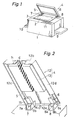
- FIG 1 is an overall perspective view of an electrostatic copying apparatus which comprises an optical means (not shown) which is scanned horizontally in the lateral direction (right and left direction in Figure 1) of an apparatus housing 1 for projecting an image of an original document 2, shown by phantom lines, through a slit onto a moving photoconductive surface.
- a transparent glass plate 3 is mounted on the top surface of a housing 1 to support the original document 2 with part of the aforementioned movable optical means being mounted beneath the transparent glass plate 3.
- the original document 2 on the transparent glass plate 3 is covered during copying with a document cover lid 4 supported by supporting rods 5 and 6.
- the bases of the supporting rods 5 and 6 are pivotally mounted by means of hinge members 7 and 8 fixed on the rear side of the housing 1.
- the front or rear side of the document cover lid 4, as viewed by the operator, can be pivotally raised above the transparent glass plate 3 as shown in Figure 1.
- a feeding cassette 9 loaded with copy papers is detachably mounted to one end wall of the apparatus housing 1, and a copy collection tray 10 is mounted to the other end wall so as to receive copy papers to be reproduced.
- Operating ccntrols 11 are located on the upper front portion of the housing 1.
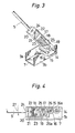
- FIG. 2 is an enlarged perspective view in the vicinity of the document cover lid 4, and Figure 3 is an enlarged perspective view in the vicinity of the base of the supporting rod 5, with parts broken away, showing further details of its construction.
- the document cover lid 4 comprises a frame 12 of rigid material and a retaining pad 13 manufactured of an elastic material, for example polyurethane, which is adhered to the underside of the rigid frame 12 facing the transparent glass plate 3.
- the rigid frame 12 comprises a rectangular flat portion 12a and three vertical walls 12b, 12c and 12d which are located about the front and two side edges of the flat portion 12a so as to leave the hinge members 7 and 8 at the rear of the lid exposed.
- the depth "d" of the retaining pad 13 is greater than the height "h" of each wall 12b, 12c and 12d. Therefore, when the document cover lid 4 is pivoted downward to cover the original document 2 on the transparent glass plate 3, the retaining pad 13 holds the original document 2 flat against the top surface of the glass plate 3.
- the hinge members 7 and 8 are each formed in an upwardly open U-shape.
- a horizontal supporting shaft 14 is pivotally mounted through supporting portions 7a and 7b, 8a and 8b.
- Supporting rods 5 and 6 extend along the insides of walls 12c and 12d, and are fixedly mounted to the rigid frame 12.
- the bases of the supporting rods 5 and 6 extend at right angles from and are fixed to the supporting shaft 14. Either a single shaft 14 can be provided passing through both hinges 7 and 8 or a separate short supporting shaft 14 may be provided for each hinge.
- Figure 4 shows the base of the supporting rod 5 when the document cover lid 4 is in a closed position.
- a cylindrical positioning member 15, having its axis parallel to that of the supporting shaft 14, is fixed to the hinge member 7.
- the peripheral surface of the positioning member 15 can be considered as a first frictional surface 16.
- a guide member 17 is fixedly mounted to the base of the supporting rod 5.
- the guide member 17 is formed internally as a guide tube 18 extending parallel with the axis of the supporting rod 5.
- a contact member 19 to be in contact with the positioning member 15 is inserted in one end of the guide tube 18 facing the supporting shaft 14, and an end plate 20 closes the other end of the guide tube.
- a supporting plate 21, provided with an adjustment screw 22, is attached adjacent to the end plate 20 in the guide hole 18.
- a movable receiving plate 23 is adjustably disposed between the supporting plate 21 and the contact member 19 so as to be in contact with the adjustment screw 22.and in alignment with the guide tube 18.
- the end plate 20 has a hole 24 to permit passage therethrough of a screwdriver for turning the adjustment screw 22 when required.
- a spring 25 is provided between the receiving plate 23 and the contact member 19. Accordingly the contact member 19 is resiliently urged toward the supporting shaft 14 by the spring 25 with the spring force being adjustable by rotation of the adjustment screw 22.
- the contact member 19 has a semi-cylindrical end face which constitutes a second frictional surface 26 which is parallel with the axis 16a of the positioning member 15 and is convex towards the supporting shaft 14.
- the positioning member 15 is so placed that the second frictional surface 26 of the contact member 19 is always urged into contact with the first frictional surface 16 by the action of the spring 25.
- the positioning member 15 is so located that the centre line 26a of the second frictional surface 26 extending lengthwise of the guide tube 18 is lower than the axis 16a of the first frictional surface 16.
- the first frictional surface 16 contacts with the second frictional surface 26 at a position which is lower than the axis 16a of the positioning member 15. This causes a moment, indicated by arrow 27,to be exerted by the positioning member 15 on the guide member 17 and the supporting rod 5 about the supporting shaft 14 in a downward direction caused by the bias of the spring 25.
- the original document 2 can be held firmly on the transparent glass plate 3.
- the base of the supporting rod 6 has the same construction as that of the supporting rod 5.
Landscapes
- Physics & Mathematics (AREA)
- General Physics & Mathematics (AREA)
- Holders For Sensitive Materials And Originals (AREA)
- Exposure Or Original Feeding In Electrophotography (AREA)
Applications Claiming Priority (2)
| Application Number | Priority Date | Filing Date | Title |
|---|---|---|---|
| JP54167022A JPS5926013B2 (ja) | 1979-12-21 | 1979-12-21 | 複写機の原稿抑えの保持機構 |
| JP167022/79 | 1979-12-21 |
Publications (2)
| Publication Number | Publication Date |
|---|---|
| EP0032305A1 true EP0032305A1 (de) | 1981-07-22 |
| EP0032305B1 EP0032305B1 (de) | 1984-03-21 |
Family
ID=15841932
Family Applications (1)
| Application Number | Title | Priority Date | Filing Date |
|---|---|---|---|
| EP80304652A Expired EP0032305B1 (de) | 1979-12-21 | 1980-12-19 | Abstützmechanik für die Vorlagenabdeckung eines Kopiergerätes |
Country Status (4)
| Country | Link |
|---|---|
| US (1) | US4365893A (de) |
| EP (1) | EP0032305B1 (de) |
| JP (1) | JPS5926013B2 (de) |
| DE (1) | DE3067223D1 (de) |
Families Citing this family (17)
| Publication number | Priority date | Publication date | Assignee | Title |
|---|---|---|---|---|
| JPS5934386A (ja) * | 1982-08-20 | 1984-02-24 | 株式会社東芝 | 開閉装置 |
| JPS5938734A (ja) * | 1982-08-30 | 1984-03-02 | Kato Denki Kk | 原稿圧着板開閉装置 |
| JPS6055334A (ja) * | 1983-09-06 | 1985-03-30 | Kato Denki Kk | 原稿圧着板の開閉装置 |
| JPS6274241U (de) * | 1985-10-25 | 1987-05-12 | ||
| US4673101A (en) * | 1986-05-08 | 1987-06-16 | Micrion Limited Partnership | Evacuable chamber enclosing |
| US4853750A (en) * | 1987-02-26 | 1989-08-01 | Sharp Kabushiki Kaisha | Document holder for a copier and hinge mechanism therefor |
| JP2709967B2 (ja) * | 1989-11-28 | 1998-02-04 | 三田工業株式会社 | 自動原稿搬送装置 |
| JPH04317964A (ja) * | 1991-04-16 | 1992-11-09 | Hitachi Building Syst Eng & Service Co Ltd | エレベータのかご内操作盤 |
| JPH0676950U (ja) * | 1991-12-11 | 1994-10-28 | 加藤電機株式会社 | 原稿圧着板の開閉装置 |
| US5621501A (en) * | 1993-10-25 | 1997-04-15 | Canon Kabushiki Kaisha | Opening-closing mechanism for an automatic original feeding apparatus |
| JP3641357B2 (ja) * | 1997-09-24 | 2005-04-20 | 加藤電機株式会社 | 原稿圧着板開閉装置 |
| JP3728385B2 (ja) * | 1998-12-11 | 2005-12-21 | 加藤電機株式会社 | 原稿圧着板開閉装置 |
| JP3977213B2 (ja) * | 2002-09-06 | 2007-09-19 | シャープ株式会社 | 原稿カバーのヒンジ機構 |
| ITMI20031950A1 (it) * | 2003-10-10 | 2005-04-11 | Agostino Ferrari Spa | Gruppo cerniera per la connessione articolata di un pannello ad apertura verticale ad un elemento di arredamento |
| TWI328996B (en) * | 2006-08-03 | 2010-08-11 | Avision Inc | Hinge device which can be adjusted laterally and scan apparatus using the same |
| ITMI20112422A1 (it) * | 2011-12-29 | 2013-06-30 | Mibb Srl | Cerniera per anta ribaltabile per una vaschetta incorporata in un mobiletto |
| JP6233914B2 (ja) * | 2013-01-25 | 2017-11-22 | 株式会社ナチュラレーザ・ワン | 原稿圧着板開閉装置並びに事務機器 |
Citations (5)
| Publication number | Priority date | Publication date | Assignee | Title |
|---|---|---|---|---|
| US2248646A (en) * | 1938-10-27 | 1941-07-08 | Small Howard | Photographic film tensioning mechanism |
| US3095225A (en) * | 1962-01-29 | 1963-06-25 | Sanymetal Products Company Inc | Automatic door locking assemblies |
| GB1318753A (en) * | 1969-09-29 | 1973-05-31 | Xerox Corp | Cover controlling apparatus |
| GB1355878A (en) * | 1970-06-29 | 1974-06-05 | Xerox Corp | Platen cover |
| US4124296A (en) * | 1976-09-01 | 1978-11-07 | Canon Kabushiki Kaisha | Original urging device |
Family Cites Families (5)
| Publication number | Priority date | Publication date | Assignee | Title |
|---|---|---|---|---|
| GB958156A (en) * | 1962-03-20 | 1964-05-13 | Bloxvich Lock Stamping | Improvements in hinges |
| US3642376A (en) * | 1970-06-29 | 1972-02-15 | Xerox Corp | Removable platen cover |
| CA939464A (en) * | 1972-02-29 | 1974-01-08 | Martin R. Lambertz | Lavatory door hinge |
| US4097145A (en) * | 1977-01-03 | 1978-06-27 | Pitney-Bowes, Inc. | Means for self-positioning platen covers |
| US4114236A (en) * | 1977-07-28 | 1978-09-19 | Minnesota Mining & Manufacturing Company | Hinge structure for platen covers |
-
1979
- 1979-12-21 JP JP54167022A patent/JPS5926013B2/ja not_active Expired
-
1980
- 1980-12-18 US US06/218,013 patent/US4365893A/en not_active Expired - Fee Related
- 1980-12-19 EP EP80304652A patent/EP0032305B1/de not_active Expired
- 1980-12-19 DE DE8080304652T patent/DE3067223D1/de not_active Expired
Patent Citations (5)
| Publication number | Priority date | Publication date | Assignee | Title |
|---|---|---|---|---|
| US2248646A (en) * | 1938-10-27 | 1941-07-08 | Small Howard | Photographic film tensioning mechanism |
| US3095225A (en) * | 1962-01-29 | 1963-06-25 | Sanymetal Products Company Inc | Automatic door locking assemblies |
| GB1318753A (en) * | 1969-09-29 | 1973-05-31 | Xerox Corp | Cover controlling apparatus |
| GB1355878A (en) * | 1970-06-29 | 1974-06-05 | Xerox Corp | Platen cover |
| US4124296A (en) * | 1976-09-01 | 1978-11-07 | Canon Kabushiki Kaisha | Original urging device |
Also Published As
| Publication number | Publication date |
|---|---|
| JPS5926013B2 (ja) | 1984-06-23 |
| EP0032305B1 (de) | 1984-03-21 |
| JPS5689761A (en) | 1981-07-21 |
| DE3067223D1 (en) | 1984-04-26 |
| US4365893A (en) | 1982-12-28 |
Similar Documents
| Publication | Publication Date | Title |
|---|---|---|
| EP0032305A1 (de) | Abstützmechanik für die Vorlagenabdeckung eines Kopiergerätes | |
| EP0120201B2 (de) | Elektrostatisches Kopiergerät | |
| US5313257A (en) | Paper cassette for use in an image forming device | |
| US4124296A (en) | Original urging device | |
| US7536148B2 (en) | Image scanning device with a pivotable automatic document feeder | |
| GB2250478A (en) | Mounting a thermal print head in a printer | |
| JP5951583B2 (ja) | 画像読取装置及び画像読取装置を備えた画像形成装置 | |
| US4172660A (en) | Copying apparatus cover | |
| US5003347A (en) | Opening-closing mechanism for automatic document feeder | |
| US7073787B2 (en) | Media tray damper | |
| US4154527A (en) | Arrangement for supporting original documents on an optical copying machine | |
| US5401014A (en) | Sheet feeder for an image forming apparatus | |
| US4926214A (en) | Original-holding cover | |
| JPH03114037A (ja) | 静電複写機における原稿押え装置 | |
| US20230241908A1 (en) | Apparatuses for mounting control panels in printing devices | |
| JPH0142094Y2 (de) | ||
| JP3484326B2 (ja) | プロセスカートリッジ及び画像形成装置 | |
| JP3414860B2 (ja) | 画像形成装置 | |
| JP2910021B2 (ja) | 画像形成装置 | |
| USRE30878E (en) | Copying apparatus cover | |
| JPH0651411A (ja) | 複写機の原稿押え装置 | |
| US5737805A (en) | Self rising cover assembly for machine housing | |
| JPH0335663B2 (de) | ||
| JPH09106014A (ja) | 原稿圧着板の取付装置 | |
| JP2009258325A (ja) | 画像形成装置 |
Legal Events
| Date | Code | Title | Description |
|---|---|---|---|
| PUAI | Public reference made under article 153(3) epc to a published international application that has entered the european phase |
Free format text: ORIGINAL CODE: 0009012 |
|
| AK | Designated contracting states |
Designated state(s): DE FR GB IT NL |
|
| 17P | Request for examination filed |
Effective date: 19811117 |
|
| ITF | It: translation for a ep patent filed | ||
| GRAA | (expected) grant |
Free format text: ORIGINAL CODE: 0009210 |
|
| AK | Designated contracting states |
Designated state(s): DE FR GB IT NL |
|
| REF | Corresponds to: |
Ref document number: 3067223 Country of ref document: DE Date of ref document: 19840426 |
|
| ET | Fr: translation filed | ||
| PLBE | No opposition filed within time limit |
Free format text: ORIGINAL CODE: 0009261 |
|
| STAA | Information on the status of an ep patent application or granted ep patent |
Free format text: STATUS: NO OPPOSITION FILED WITHIN TIME LIMIT |
|
| 26N | No opposition filed | ||
| ITTA | It: last paid annual fee | ||
| PGFP | Annual fee paid to national office [announced via postgrant information from national office to epo] |
Ref country code: GB Payment date: 19931209 Year of fee payment: 14 Ref country code: FR Payment date: 19931209 Year of fee payment: 14 |
|
| PGFP | Annual fee paid to national office [announced via postgrant information from national office to epo] |
Ref country code: DE Payment date: 19931227 Year of fee payment: 14 |
|
| PGFP | Annual fee paid to national office [announced via postgrant information from national office to epo] |
Ref country code: NL Payment date: 19931231 Year of fee payment: 14 |
|
| PG25 | Lapsed in a contracting state [announced via postgrant information from national office to epo] |
Ref country code: GB Effective date: 19941219 |
|
| PG25 | Lapsed in a contracting state [announced via postgrant information from national office to epo] |
Ref country code: NL Effective date: 19950701 |
|
| GBPC | Gb: european patent ceased through non-payment of renewal fee |
Effective date: 19941219 |
|
| PG25 | Lapsed in a contracting state [announced via postgrant information from national office to epo] |
Ref country code: FR Effective date: 19950831 |
|
| NLV4 | Nl: lapsed or anulled due to non-payment of the annual fee |
Effective date: 19950701 |
|
| PG25 | Lapsed in a contracting state [announced via postgrant information from national office to epo] |
Ref country code: DE Effective date: 19950901 |
|
| REG | Reference to a national code |
Ref country code: FR Ref legal event code: ST |