EP0032462A1 - Scheibenbremse - Google Patents
Scheibenbremse Download PDFInfo
- Publication number
- EP0032462A1 EP0032462A1 EP81300188A EP81300188A EP0032462A1 EP 0032462 A1 EP0032462 A1 EP 0032462A1 EP 81300188 A EP81300188 A EP 81300188A EP 81300188 A EP81300188 A EP 81300188A EP 0032462 A1 EP0032462 A1 EP 0032462A1
- Authority
- EP
- European Patent Office
- Prior art keywords
- disc
- caliper
- pad spring
- friction pads
- carrier
- Prior art date
- Legal status (The legal status is an assumption and is not a legal conclusion. Google has not performed a legal analysis and makes no representation as to the accuracy of the status listed.)
- Granted
Links
Images




Classifications
-
- F—MECHANICAL ENGINEERING; LIGHTING; HEATING; WEAPONS; BLASTING
- F16—ENGINEERING ELEMENTS AND UNITS; GENERAL MEASURES FOR PRODUCING AND MAINTAINING EFFECTIVE FUNCTIONING OF MACHINES OR INSTALLATIONS; THERMAL INSULATION IN GENERAL
- F16D—COUPLINGS FOR TRANSMITTING ROTATION; CLUTCHES; BRAKES
- F16D55/00—Brakes with substantially-radial braking surfaces pressed together in axial direction, e.g. disc brakes
- F16D55/02—Brakes with substantially-radial braking surfaces pressed together in axial direction, e.g. disc brakes with axially-movable discs or pads pressed against axially-located rotating members
- F16D55/22—Brakes with substantially-radial braking surfaces pressed together in axial direction, e.g. disc brakes with axially-movable discs or pads pressed against axially-located rotating members by clamping an axially-located rotating disc between movable braking members, e.g. movable brake discs or brake pads
- F16D55/224—Brakes with substantially-radial braking surfaces pressed together in axial direction, e.g. disc brakes with axially-movable discs or pads pressed against axially-located rotating members by clamping an axially-located rotating disc between movable braking members, e.g. movable brake discs or brake pads with a common actuating member for the braking members
- F16D55/225—Brakes with substantially-radial braking surfaces pressed together in axial direction, e.g. disc brakes with axially-movable discs or pads pressed against axially-located rotating members by clamping an axially-located rotating disc between movable braking members, e.g. movable brake discs or brake pads with a common actuating member for the braking members the braking members being brake pads
- F16D55/226—Brakes with substantially-radial braking surfaces pressed together in axial direction, e.g. disc brakes with axially-movable discs or pads pressed against axially-located rotating members by clamping an axially-located rotating disc between movable braking members, e.g. movable brake discs or brake pads with a common actuating member for the braking members the braking members being brake pads in which the common actuating member is moved axially, e.g. floating caliper disc brakes
- F16D55/2265—Brakes with substantially-radial braking surfaces pressed together in axial direction, e.g. disc brakes with axially-movable discs or pads pressed against axially-located rotating members by clamping an axially-located rotating disc between movable braking members, e.g. movable brake discs or brake pads with a common actuating member for the braking members the braking members being brake pads in which the common actuating member is moved axially, e.g. floating caliper disc brakes the axial movement being guided by one or more pins engaging bores in the brake support or the brake housing
- F16D55/227—Brakes with substantially-radial braking surfaces pressed together in axial direction, e.g. disc brakes with axially-movable discs or pads pressed against axially-located rotating members by clamping an axially-located rotating disc between movable braking members, e.g. movable brake discs or brake pads with a common actuating member for the braking members the braking members being brake pads in which the common actuating member is moved axially, e.g. floating caliper disc brakes the axial movement being guided by one or more pins engaging bores in the brake support or the brake housing by two or more pins
-
- F—MECHANICAL ENGINEERING; LIGHTING; HEATING; WEAPONS; BLASTING
- F16—ENGINEERING ELEMENTS AND UNITS; GENERAL MEASURES FOR PRODUCING AND MAINTAINING EFFECTIVE FUNCTIONING OF MACHINES OR INSTALLATIONS; THERMAL INSULATION IN GENERAL
- F16D—COUPLINGS FOR TRANSMITTING ROTATION; CLUTCHES; BRAKES
- F16D65/00—Parts or details
- F16D65/02—Braking members; Mounting thereof
- F16D65/04—Bands, shoes or pads; Pivots or supporting members therefor
- F16D65/092—Bands, shoes or pads; Pivots or supporting members therefor for axially-engaging brakes, e.g. disc brakes
- F16D65/095—Pivots or supporting members therefor
- F16D65/097—Resilient means interposed between pads and supporting members or other brake parts
- F16D65/0973—Resilient means interposed between pads and supporting members or other brake parts not subjected to brake forces
- F16D65/0974—Resilient means interposed between pads and supporting members or other brake parts not subjected to brake forces acting on or in the vicinity of the pad rim in a direction substantially transverse to the brake disc axis
- F16D65/0975—Springs made from wire
Definitions
- This invention relates to disc brakes and, particularly to disc brakes of the kind including a carrier adapted to be secured to a non-rotatable part of a vehicle and having two circumferentially spaced arm portions which straddle respectively the outer circumference of a rotatable disc, a pair of friction pads disposed on opposite sides of the disc and being supported on the arm portions of the carrier to slide in the direction of the axis of the disc, a caliper mounted on the carrier to slide in the direction of the axis of the disc and straddling the outer circumference of the disc, and a brake actuator incorporated in the caliper for applying one friction pad against one surface of the disc.
- the reaction force of the brake actuator displaces the caliper on the carrier to apply the other friction pad against the other surface of the disc.
- the braking torque generated at the friction pads may directly received by the arm portions of the carrier.
- one or two pad springs formed of a sheet metal are mounted between the carrier, the caliper and the friction pads to bias the caliper radially outwards and friction pads radially inwards with respect to the axis of the disc so as to take up the manufacturing tolerance, to prevent vibrations of the caliper-and of the friction pads and to suppress chattering noises in operating the vehicle.
- the pad spring is formed of a rod member which is interposed between the caliper and friction pads and is retained on the caliper.
- the pad spring acts to suspend the friction pads from the caliper when the caliper has been disassembled from the carrier.
- the pad spring, the caliper and the friction pads constitute a sub-assembly, thus, assembling and disassembling operations can be simplified.
- the pad spring is forned of two separate rod members which are connected with each other by connecting members.
- a carrier 2 is adapted to be connected to a non-rotatable part of a vehicle at one side (the upper side as seen in Fig. 1) of a rotatable disc 1, and has two circumferentially spaced arm portions 2a and 2b which extend respectively in the direction of the axis of the disc 1 and straddle respectively the outer circumference of the disc 1.
- the arm portions 2a and 2b define therebetween a friction pad receiving space A.
- a pair of friction pads 3 and 4 having respectively backing plates 3a and 4a are received in the space A and supported on radially outwardly facing shoulders formed on the arm portions 2a and 2b to slide in the direction of the axis of the disc 1.
- the arm portions 2a and 2b of the carrier 2 receive directly the braking torque generated at the friction pads 3 and'4 in applying the brake.
- a caliper 7 is slidably mounted on the carrier 2 through a pair of guide pins 5 and 6.
- the caliper 7 straddles the outer circumference of the disc 1 and includes a limb portion 7a located on the rear side of the friction pad 4, and a bridge portion 7b radially outwards of the circumference of the disc 1.
- a brake actuator 8 (such as shown in Fig. 22) is incorporated in the other limb portion of the caliper 7 to act on the friction pad 3.
- a pad spring 9 is interposed between the caliper 7 and the friction pads 3 and 4.
- the pad spring 9 is formed of a rod member such as a resilient steel wire rod to have the configuration as shown in Fig. 3 by means of a bending process.
- the pad spring 9 has generally the form of a rectangle and comprises friction pad engaging portions 9a and 9b to engage with the upper surfaces of backing plates 3a and 4a of the friction pads 3 and 4 to constitute two opposite sides of the rectangle, arm portions 9c, 9d, 9e and 9f constituting another two opposite sides of the rectangle, and retaining portions 9g, 9h, 9i and 9j positioned on the central portion of the second mentioned two opposite sides of the rectangle.
- the retaining portions 9g and 9h are formed of the central portion of the original wire rod and have a generally U-shape, and the retaining portions 9i and 9j are separated.
- the retaining portions 9g to 9j extend through an opening 10 of the bridge portion 7b of the caliper 7 and engage with the outer surfaces of the bridge portion 7b.
- the friction pad engaging portions 9a and 9b resiliently engage with the backing plates 3a and 4a of the friction pads 3 and 4.
- the arm portions 9c to 9f engage with the inner surface of the bridge portion 7b as shown in Fig. 2.
- axially extending projections or ridges B are formed on the inner surface of the bridge portion 7b of the caliper 7 as shown in Fig. 2 so as to contact with the pad spring 9 and to receive the resilient force therefrom.
- hook portions 3b and 4b are adapted to engage with the engaging portion 9a of the pad spring 9 and the hook portions 3c and 4c are adapted to engage with the engaging portion 9b of the pad spring 9, when the caliper 7 has been disassembled from the carrier 2 as shown in Fig. 4, whereby the friction pads 3 and 4 are suspended from the caliper 7 through the pad spring 9.
- the caliper 7, the pad spring 9 and the friction pads 3 and 4 constitute a sub-assembly C, thus, the assembling or disassembling operations can be performed very easily and simply. In that condition, the arm portions 9c to 9e of the pad spring do not contact with the inner surface of the bridge portion 7b.
- the arrangement is particularly advantageous in disc brakes of the so-called direct mounting type wherein the carrier 2 is integrally formed on the non-rotatable part of the vehicle.
- the sub-assembly C is mounted on the carrier 2 with the friction pads 3 and 4 being located on the opposite sides of the disc 1 and, thereafter, the guide pins 5 and 6 are screwed into threaded holes formed in the carrier 2.
- the engaging portions 9a and 9b of the pad spring 9 separate automatically from the hook portions 3b, 3c, 4b and 4c of the friction pads 3 and 4, and the pad spring 9 takes a proper position between the caliper and the friction pads as shown in Fig. 2.
- the second embodiment shown in Fig. 5 is generally similar to the first embodiment.
- the pad spring of the second embodiment consists of two separate rod members 19 and 19', however, the general configuration, arrangement, the function and the operational characteristics are similar to the first embodiment.
- disc brakes shown in the drawings are generally similar, and the same or the corresponding numerals have been applied to corresponding parts or portions, and detailed descriptions therefor are omitted.
- Figs.6 to 8 illustrate the third embodiment of the invention.
- the pad spring of the third embodiments is, similarly to that of the second embodiment, formed of two separated rod members 29 and 29', however, the retaining portions 29g, 29i, 29'h and 29'j of the pad springs 29, 29' are located on the plane defined by remaining portions 29a; 29c and 29e, and 29'b, 29'd and 29'f.
- the retaining portions 29g, 29'h, 29i and 29'j are respectively inserted into recesses lla, llb, llc and lld which are formed in the axial edges of the opening 10 of the bridge portion 7b, and are retained thereby.
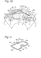
- the pad spring 39 of the fourth embodiment illustrated in Figs.9 to 11 is generally similar to the pad spring 9 in the first embodiment, but the pad spring is denoted by the' numeral 39 and encircles the outer circumference of the caliper 7 with retaining portions 39gto 39j of the pad spring 39 being hung on the upper surface of the caliper 7. There are provided projections 7e and 7f on the outer circumference of the caliper 7 to engage with the arm portions 39c to 39f to receive the resilient force of the pad spring 39.
- the pad spring of the fifth embodiment of the invention illustrated in Figs.12 to 14 consists, similar to the third embodiment, of two rod members 49 and 49' with retaining portions 49g, 49'h, 49i and 49'j being inserted respectively into recesses 11'a to 11'd of the caliper 7.
- the pad spring (49 and 49') is generally similar to the pad spring 39.
- Figs. 15to 18 illustrate the sixth embodiment of the invention, wherein the pad spring is denoted by the numeral 59 which is generally similar to the pad spring 9 of the first embodiment.
- the friction pads 3 and 4 are modified to have recessed portions 3d, 3e, 4d and 4e in the upper surface of the backing plates 3a and 4a respectively.
- the recessed portions 3d, 3e, 4d and 4e are respectively spaced from the hook portions 3b, 3c, 4b and 4c in the circumferentially outward directions.
- the engaging portions 59a and 59b of the pad spring 59 engage respectively with the recessed portions 3d and 4d and.with the recessed portions 3e and 4e so that the displacement of the friction pads in the circumferential directions can be controlled.
- Figs. 19 and 20 illustrates the seventh embodiment of the invention.
- the pad spring is similar to the pad spring 39 in the fourth embodiment shown in Fig. 11 and is denoted by the numeral 69.
- the friction pads 3 and 4 are similar to the friction pads of the sixth embodiment.
- the pad spring is formed by bending two rod members, and connecting respective adjacent free ends of the rod members by connecting members respectively. Similar to the embodiments shown in Figs. 5, 8 and 14, it is possible to simplify the manufacturing process and to reduce costs by forming the pad spring of two rod members, however, it is rather difficult to equalize the spring force between two separate pad springs. Such shortcomings can be avoided by connecting the free ends of the rod members with one another to form an integrally connected pad spring.
- the free ends of the rod members are connected by means of sleeve-like members.
- Figs.21 to 23 illustrate the eighth embodiment of the invention.
- the pad spring consists, as clearly shown in Fig. 23, of two rod members 79 and 79' which are bent into similar configurations.
- the free end portions 79a and 79b of the rod member 79 are respectively connected to the free end portions 79'a and 79'b of the rod member 79' through connecting sleeves 16.
- the connecting sleeves 16 are preferably metal tubes with the inner diameter of which being adapted to forcibly receive the end portions of the pad spring.
- the end portions of the pad spring may be connected by any other suitable connecting members, and may be secured to the connecting members utilizing suitable technique such as caulking, soldering or bonding.
- the pad spring 79, 79' acts on friction pads 3 and 4 through connecting sleeves 16, thus, it is possible to equalize the spring force acting on the friction pads 3 and 4 irrespec- t ive of the relative axial displacement of the caliper 7 and the friction pad 3.
- horizon- .tally extending retaining portions 79g, 79h, 79'i and 79'j of the pad spring engage with the inner surface of the caliper 7 to transmit the spring force to the caliper 7.
- Fig. 22 illustrates a typical construction of the brake actuator 8 which comprises a cylinder bore 12, a piston 13 slidable in the cylinder bore-12, a seal ring 14 provided between the cylinder bore 12 and the piston 13, and a dust boot 15.
- the piston 13 displaces leftward thereby pressing the friction pad 3 against the right surface of the disc 1.
- the reaction force of the brake actuator displaces the caliper 7 in the leftward direction, so that the limb portion 7a presses the backing plate 4a of the friction pad 4 to apply the same against the left surface of the disc.
- the central portions of respective rod members 79 and 79' are bent to have generally horizontal U-shaped configuration as seen in Fig.
- a reinforcing beam integrally connecting the arm portions 2a and 2b of the carrier 7.
- Fig. 24 shows a modified form, wherein end portions 89a and 89b of a rod member 89 are connected respectively with end portions 89'a and 89'b of a rod member 89' through connecting members 26 which are formed by curling plate-like members around the end portions of the rod members.
- Figs. 25 and 26 show still further embodiment of the invention which is a combination of the first and eighth embodiments (Figs. 2 and 3 and Figs. 21 and 23).
- the pad spring engages with the upper surface of the bridge portion 7b of the caliper 7 and with projections or ridges 17 formed on the lower surface of the caliper 7 as similar to the first embodiment, and connecting sleeves 36 of the pad spring engages with the friction pads 3 and 4. Further, there are provided hook portions on the backing plates 3a and 4a of the friction pads 3 and 4 to engage with the connecting sleeves 36 when the caliper 7 and the friction pads 3 and 4 have been disassembled from the carrier 2.
- the disc brake according to the invention comprises a pad spring formed of a rod member and is retained on the caliper to act between the caliper and a pair of friction pads.
- the pad spring is not mounted on the carrier and acts on the carrier through the friction pads.
Landscapes
- Engineering & Computer Science (AREA)
- General Engineering & Computer Science (AREA)
- Mechanical Engineering (AREA)
- Braking Arrangements (AREA)
Applications Claiming Priority (4)
| Application Number | Priority Date | Filing Date | Title |
|---|---|---|---|
| JP501880A JPS56105129A (en) | 1980-01-19 | 1980-01-19 | Disk brake |
| JP5018/80 | 1980-01-19 | ||
| JP31672/80U | 1980-03-11 | ||
| JP3167280U JPS56133137U (de) | 1980-03-11 | 1980-03-11 |
Publications (2)
| Publication Number | Publication Date |
|---|---|
| EP0032462A1 true EP0032462A1 (de) | 1981-07-22 |
| EP0032462B1 EP0032462B1 (de) | 1984-01-04 |
Family
ID=26338895
Family Applications (1)
| Application Number | Title | Priority Date | Filing Date |
|---|---|---|---|
| EP81300188A Expired EP0032462B1 (de) | 1980-01-19 | 1981-01-16 | Scheibenbremse |
Country Status (3)
| Country | Link |
|---|---|
| US (1) | US4394891A (de) |
| EP (1) | EP0032462B1 (de) |
| DE (1) | DE3161807D1 (de) |
Cited By (12)
| Publication number | Priority date | Publication date | Assignee | Title |
|---|---|---|---|---|
| FR2517399A1 (fr) * | 1981-11-30 | 1983-06-03 | Dba | Frein a disque et patin pour un tel frein |
| FR2552512A1 (fr) * | 1983-09-23 | 1985-03-29 | Citroen Sa | Epingle d'etrier flottant et son montage sur un frein a disque |
| EP0248385A1 (de) * | 1986-06-04 | 1987-12-09 | LUCAS INDUSTRIES public limited company | Scheibenbremse und Blattfeder zur Verwendung in einer solchen |
| FR2606107A1 (fr) * | 1986-10-31 | 1988-05-06 | Bendix France | Plaquette pour frein a disque et frein a disque equipe de telles plaquettes |
| WO1990015266A1 (de) * | 1989-06-10 | 1990-12-13 | Alfred Teves Gmbh | Teilbelag-scheibenbremse, insbesondere für kraftfahrzeuge |
| WO1991008401A1 (de) * | 1989-11-24 | 1991-06-13 | Alfred Teves Gmbh | Niederhaltefeder für teilbelag-scheibenbremsen und zugehöriges gehäuse und bremsbacken |
| DE3942802A1 (de) * | 1989-12-23 | 1991-06-27 | Teves Gmbh Alfred | Drahtniederhaltefeder fuer bremsbacken |
| WO1992000465A1 (de) * | 1990-06-26 | 1992-01-09 | Knorr-Bremse Ag | Belaghalterung in scheibenbremsen für strassenfahrzeuge, insbesondere nutzfahrzeuge |
| DE4100303A1 (de) * | 1991-01-08 | 1992-07-09 | Teves Gmbh Alfred | Schwimmsattel-teilbelagscheibenbremse |
| DE19824581A1 (de) * | 1998-06-02 | 1999-12-09 | Continental Teves Ag & Co Ohg | Federanordnung für eine Teilbelag-Scheibenbremse |
| US7178641B2 (en) | 2001-09-06 | 2007-02-20 | Hyundai Motor Company | Automobile brake caliper for reducing noise |
| EP1798437A1 (de) * | 2005-12-14 | 2007-06-20 | KNORR-BREMSE SYSTEME FÜR NUTZFAHRZEUGE GmbH | Bremsbelaghalterung |
Families Citing this family (19)
| Publication number | Priority date | Publication date | Assignee | Title |
|---|---|---|---|---|
| JPS5844534U (ja) * | 1981-09-18 | 1983-03-25 | トキコ株式会社 | デイスクブレ−キ |
| FR2576379B1 (fr) * | 1985-01-23 | 1987-03-20 | Bendix France | Frein a disque a etrier coulissant |
| DE3532975A1 (de) * | 1985-09-16 | 1987-03-19 | Teves Gmbh Alfred | Teilbelag-scheibenbremse |
| DE3808139A1 (de) * | 1988-03-11 | 1989-09-21 | Teves Gmbh Alfred | Teilbelag-scheibenbremse, insbesondere innenumgreifende scheibenbremse |
| DE3811385A1 (de) * | 1988-04-05 | 1989-10-19 | Teves Gmbh Alfred | Niederhaltefeder |
| DE3938881A1 (de) * | 1989-11-24 | 1991-05-29 | Teves Gmbh Alfred | Bremsbackenfeder |
| DE4131130B4 (de) * | 1990-11-13 | 2005-02-03 | Continental Teves Ag & Co. Ohg | Teilbelagscheibenbremse und Bremsklotz |
| DE19626299A1 (de) * | 1996-07-01 | 1998-01-08 | Teves Gmbh Alfred | Federanordnung für eine Schwimmsattelscheibenbremse |
| JP3519692B2 (ja) * | 2001-03-12 | 2004-04-19 | 三陽工業株式会社 | クランプ装置 |
| WO2004007986A1 (en) † | 2002-07-15 | 2004-01-22 | Freni Brembo S.P.A. | Disc brake pad |
| DE502004006686D1 (de) * | 2003-10-14 | 2008-05-08 | Continental Teves Ag & Co Ohg | Teilbelagscheibenbremse mit einer federanordnung |
| JP4086827B2 (ja) * | 2004-09-15 | 2008-05-14 | 曙ブレーキ工業株式会社 | フローティングキャリパ型ディスクブレーキ |
| FR2876427B1 (fr) * | 2004-10-08 | 2008-03-14 | Bosch Gmbh Robert | Element de friction muni d'un moyen de rappel et frein a disque comportant un tel element de friction |
| US7267208B2 (en) * | 2004-12-14 | 2007-09-11 | Akebono Corporation | Retention spring for brake pressure pads |
| GB0521326D0 (en) * | 2005-10-20 | 2005-11-30 | Bentley Motors Ltd | A pad retention device |
| KR101294666B1 (ko) * | 2011-10-04 | 2013-08-09 | 주식회사 만도 | 디스크브레이크 |
| TWI512211B (zh) * | 2013-03-20 | 2015-12-11 | Sanyang Industry Co Ltd | 煞車卡鉗結構 |
| US9605721B1 (en) | 2015-09-03 | 2017-03-28 | Bendix Spicer Foundation Brake Llc | Wear optimized pad design |
| US9976610B2 (en) | 2015-09-03 | 2018-05-22 | Bendix Spicer Foundation Brake Llc | Wear optimized pad design |
Family Cites Families (11)
| Publication number | Priority date | Publication date | Assignee | Title |
|---|---|---|---|---|
| US3710896A (en) * | 1970-11-09 | 1973-01-16 | Wagner Electric Corp | Anti-rattle device for a disc brake |
| DE2340241C3 (de) * | 1973-08-09 | 1983-12-08 | Alfred Teves Gmbh, 6000 Frankfurt | Schwimmsattel-Teilbelag-Scheibenbremse, insbesondere für Kraftfahrzeuge |
| DE2408519C2 (de) * | 1974-02-22 | 1982-07-22 | Alfred Teves Gmbh, 6000 Frankfurt | Gleitführung für den Sattel einer Schwimmsattel-Teilbelag-Scheibenbremse, insbesondere für Kraftfahrzeuge |
| GB1506709A (en) * | 1974-04-02 | 1978-04-12 | Girling Ltd | Vehicle brakes |
| GB1491903A (en) * | 1974-04-02 | 1977-11-16 | Girling Ltd | Disc brakes for vehicles |
| GB1533976A (en) * | 1974-12-24 | 1978-11-29 | Girling Ltd | Friction pad assemblies for sliding caliper disc brakes |
| DE2557302C2 (de) * | 1975-12-19 | 1985-08-08 | Volkswagenwerk Ag, 3180 Wolfsburg | Teilbelag-Scheibenbremse für Kraftfahrzeuge |
| GB1567905A (en) * | 1976-01-17 | 1980-05-21 | Girling Ltd | Disc brakes |
| FR2371606A1 (fr) * | 1976-11-19 | 1978-06-16 | Girling Ltd | Perfectionnements aux freins a disque |
| US4220223A (en) * | 1978-08-01 | 1980-09-02 | Kelsey Hayes Co. | Sliding caliper disc brake friction pad assemblies |
| US4290508A (en) * | 1978-09-14 | 1981-09-22 | Lucas Industries Limited | Disc brake pad assemblies |
-
1981
- 1981-01-12 US US06/224,486 patent/US4394891A/en not_active Expired - Lifetime
- 1981-01-16 DE DE8181300188T patent/DE3161807D1/de not_active Expired
- 1981-01-16 EP EP81300188A patent/EP0032462B1/de not_active Expired
Cited By (16)
| Publication number | Priority date | Publication date | Assignee | Title |
|---|---|---|---|---|
| FR2517399A1 (fr) * | 1981-11-30 | 1983-06-03 | Dba | Frein a disque et patin pour un tel frein |
| EP0080949A1 (de) * | 1981-11-30 | 1983-06-08 | BENDIX France | Scheibenbremse und Bremsbacken für eine derartige Bremse |
| US4560038A (en) * | 1981-11-30 | 1985-12-24 | Societe Anonyme D.B.A. | Disc brake and a pad for such a brake |
| FR2552512A1 (fr) * | 1983-09-23 | 1985-03-29 | Citroen Sa | Epingle d'etrier flottant et son montage sur un frein a disque |
| EP0248385A1 (de) * | 1986-06-04 | 1987-12-09 | LUCAS INDUSTRIES public limited company | Scheibenbremse und Blattfeder zur Verwendung in einer solchen |
| FR2606107A1 (fr) * | 1986-10-31 | 1988-05-06 | Bendix France | Plaquette pour frein a disque et frein a disque equipe de telles plaquettes |
| EP0266261A3 (en) * | 1986-10-31 | 1988-11-09 | Bendix France Societe Anonyme Dite: | Plate for a disc brake, and disc brake fitted with such a plate |
| US4784242A (en) * | 1986-10-31 | 1988-11-15 | Bendix France | Pad for a disc brake and disc brake equipped with such pads |
| WO1990015266A1 (de) * | 1989-06-10 | 1990-12-13 | Alfred Teves Gmbh | Teilbelag-scheibenbremse, insbesondere für kraftfahrzeuge |
| WO1991008401A1 (de) * | 1989-11-24 | 1991-06-13 | Alfred Teves Gmbh | Niederhaltefeder für teilbelag-scheibenbremsen und zugehöriges gehäuse und bremsbacken |
| DE3942802A1 (de) * | 1989-12-23 | 1991-06-27 | Teves Gmbh Alfred | Drahtniederhaltefeder fuer bremsbacken |
| WO1992000465A1 (de) * | 1990-06-26 | 1992-01-09 | Knorr-Bremse Ag | Belaghalterung in scheibenbremsen für strassenfahrzeuge, insbesondere nutzfahrzeuge |
| DE4100303A1 (de) * | 1991-01-08 | 1992-07-09 | Teves Gmbh Alfred | Schwimmsattel-teilbelagscheibenbremse |
| DE19824581A1 (de) * | 1998-06-02 | 1999-12-09 | Continental Teves Ag & Co Ohg | Federanordnung für eine Teilbelag-Scheibenbremse |
| US7178641B2 (en) | 2001-09-06 | 2007-02-20 | Hyundai Motor Company | Automobile brake caliper for reducing noise |
| EP1798437A1 (de) * | 2005-12-14 | 2007-06-20 | KNORR-BREMSE SYSTEME FÜR NUTZFAHRZEUGE GmbH | Bremsbelaghalterung |
Also Published As
| Publication number | Publication date |
|---|---|
| US4394891A (en) | 1983-07-26 |
| EP0032462B1 (de) | 1984-01-04 |
| DE3161807D1 (en) | 1984-02-09 |
Similar Documents
| Publication | Publication Date | Title |
|---|---|---|
| EP0032462B1 (de) | Scheibenbremse | |
| US4467897A (en) | Disc brake with first and second springs for preventing the vibration of friction pad | |
| US4408681A (en) | Disc brake | |
| JPS6014216B2 (ja) | フロ−ティングキャリパ・スポット型ディスクブレ−キ | |
| KR101238254B1 (ko) | 마찰 요소 및 디스크 브레이크 | |
| JPS61274126A (ja) | デイスクブレ−キ用スプリング | |
| US4858728A (en) | Brake pad retention spring, in particular for spot-type disc brakes for automotive vehicles | |
| EP3680504B1 (de) | Fahrzeugscheibenbremse | |
| US4422534A (en) | Disc brake | |
| JPS63115924A (ja) | ディスクブレーキ用パッド及び同パッドを具備したディスクブレーキ | |
| EP0560146A2 (de) | Scheibenbremsvorrichtung | |
| JP2005511999A (ja) | 車両用ブレーキ装置 | |
| GB2033987A (en) | Disc brake | |
| JP3085799B2 (ja) | 車両用ディスクブレーキ | |
| JPS628654B2 (de) | ||
| US5012902A (en) | Caliper and retaining pin spacer | |
| JPH08128475A (ja) | ディスクブレーキ用パッド戻しスプリング | |
| JPS5838655B2 (ja) | ノリモノヨウエンバンブレ−キ | |
| JPS6240184Y2 (de) | ||
| JPH0716119Y2 (ja) | ディスクブレーキ | |
| JPH0210829Y2 (de) | ||
| JPH0681968B2 (ja) | 車両用ディスクブレーキ | |
| JPS62429Y2 (de) | ||
| JPH08145090A (ja) | ディスクブレーキ用パッドスプリング | |
| JPS5839823A (ja) | デイスクブレ−キ |
Legal Events
| Date | Code | Title | Description |
|---|---|---|---|
| PUAI | Public reference made under article 153(3) epc to a published international application that has entered the european phase |
Free format text: ORIGINAL CODE: 0009012 |
|
| AK | Designated contracting states |
Designated state(s): DE FR GB IT |
|
| 17P | Request for examination filed |
Effective date: 19810810 |
|
| ITF | It: translation for a ep patent filed | ||
| ITF | It: translation for a ep patent filed | ||
| GRAA | (expected) grant |
Free format text: ORIGINAL CODE: 0009210 |
|
| AK | Designated contracting states |
Designated state(s): DE FR GB IT |
|
| REF | Corresponds to: |
Ref document number: 3161807 Country of ref document: DE Date of ref document: 19840209 |
|
| ET | Fr: translation filed | ||
| PLBE | No opposition filed within time limit |
Free format text: ORIGINAL CODE: 0009261 |
|
| STAA | Information on the status of an ep patent application or granted ep patent |
Free format text: STATUS: NO OPPOSITION FILED WITHIN TIME LIMIT |
|
| 26N | No opposition filed | ||
| ITTA | It: last paid annual fee | ||
| PGFP | Annual fee paid to national office [announced via postgrant information from national office to epo] |
Ref country code: FR Payment date: 19931231 Year of fee payment: 14 |
|
| PGFP | Annual fee paid to national office [announced via postgrant information from national office to epo] |
Ref country code: GB Payment date: 19940106 Year of fee payment: 14 |
|
| PGFP | Annual fee paid to national office [announced via postgrant information from national office to epo] |
Ref country code: DE Payment date: 19940331 Year of fee payment: 14 |
|
| PG25 | Lapsed in a contracting state [announced via postgrant information from national office to epo] |
Ref country code: GB Effective date: 19950116 |
|
| GBPC | Gb: european patent ceased through non-payment of renewal fee |
Effective date: 19950116 |
|
| PG25 | Lapsed in a contracting state [announced via postgrant information from national office to epo] |
Ref country code: FR Effective date: 19950929 |
|
| PG25 | Lapsed in a contracting state [announced via postgrant information from national office to epo] |
Ref country code: DE Effective date: 19951003 |
|
| REG | Reference to a national code |
Ref country code: FR Ref legal event code: ST |