EP0032473A1 - Volumetrische Pumpe - Google Patents
Volumetrische Pumpe Download PDFInfo
- Publication number
- EP0032473A1 EP0032473A1 EP81400031A EP81400031A EP0032473A1 EP 0032473 A1 EP0032473 A1 EP 0032473A1 EP 81400031 A EP81400031 A EP 81400031A EP 81400031 A EP81400031 A EP 81400031A EP 0032473 A1 EP0032473 A1 EP 0032473A1
- Authority
- EP
- European Patent Office
- Prior art keywords
- compartment
- seat
- membrane
- suction
- pump according
- Prior art date
- Legal status (The legal status is an assumption and is not a legal conclusion. Google has not performed a legal analysis and makes no representation as to the accuracy of the status listed.)
- Granted
Links
Images
Classifications
-
- F—MECHANICAL ENGINEERING; LIGHTING; HEATING; WEAPONS; BLASTING
- F04—POSITIVE - DISPLACEMENT MACHINES FOR LIQUIDS; PUMPS FOR LIQUIDS OR ELASTIC FLUIDS
- F04B—POSITIVE-DISPLACEMENT MACHINES FOR LIQUIDS; PUMPS
- F04B43/00—Machines, pumps, or pumping installations having flexible working members
- F04B43/02—Machines, pumps, or pumping installations having flexible working members having plate-like flexible members, e.g. diaphragms
- F04B43/025—Machines, pumps, or pumping installations having flexible working members having plate-like flexible members, e.g. diaphragms two or more plate-like pumping members in parallel
-
- F—MECHANICAL ENGINEERING; LIGHTING; HEATING; WEAPONS; BLASTING
- F04—POSITIVE - DISPLACEMENT MACHINES FOR LIQUIDS; PUMPS FOR LIQUIDS OR ELASTIC FLUIDS
- F04B—POSITIVE-DISPLACEMENT MACHINES FOR LIQUIDS; PUMPS
- F04B43/00—Machines, pumps, or pumping installations having flexible working members
- F04B43/02—Machines, pumps, or pumping installations having flexible working members having plate-like flexible members, e.g. diaphragms
- F04B43/028—Machines, pumps, or pumping installations having flexible working members having plate-like flexible members, e.g. diaphragms with in- or outlet valve arranged in the plate-like flexible member
Definitions
- the present invention relates to positive displacement positive displacement pumps or vacuum compressors.
- the pump according to the invention which is self-priming, applies, in general, to the transport by pumping of a fluid at high flow rate, in a conduit which may have a small diameter, while consuming little d energy and without the material subjected to pumping being abused, and while remaining highly reliable in operation even in the event of water hammer.
- the subject of the invention is therefore a pump formed of a sealed envelope having a suction pipe and a delivery pipe, of two membrane walls and seat, inside the envelope, which delimit between them a compartment.
- a pump formed of a sealed envelope having a suction pipe and a delivery pipe, of two membrane walls and seat, inside the envelope, which delimit between them a compartment.
- intermediate between two suction and discharge compartments communicating respectively with the pipes and which allow the passage of a fluid only from the suction compartment to the intermediate one and only from the latter to the discharge compartment, and means for alternately move the walls apart and bring them closer together, characterized in that a membrane is locally retained at its seat.
- the flow of the fluid is not interrupted.
- the suction and discharge pipes unlike known positive displacement pumps, open freely in their compartment and are not provided with any fluid retention system. This saves a lot on the power consumed for the operation of the pump.
- the seat is rigid and the membrane is retained at the seat. The membrane then serves both as a valve and as a member for modifying the volume of the intermediate compartment.
- the seat comprises a rigid grid, on the periphery of which is fixed an elastic skirt whose outer periphery is fixed to the envelope. It is then the skirt which serves as said organ.
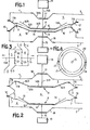
- Figures 1 and 2 are two diagrams, seen in section, illustrating the operation of a pump according to the invention.
- Figure 3 is a diagram of another variant.
- Figure 4 is a top view of the mem brane, fixed at two points, of the variant of FIG. 4.
- the pump comprises a metal casing 1, of generally parallelepiped shape.
- the interior of the casing 1 is subdivided into three compartments, one 4, suction, where the tubing 2 opens, another 5, discharge, or the tubing 3 opens and a third 6, intermediate by two walls A and B suction and discharge.
- Each partition comprises a waterproof membrane or skirt 7 and 7B fixed at 10 around the periphery of the envelope 1.
- the membrane 7 is connected by a grid 11 forming a seat to a wall 12 and the membrane 7B to a wall 12B by a grid of the same type. These walls 12 and 12B are provided with an opening.
- the bulkhead assembly A (membrane 7, valve 16 and cup 14) is integral with a rod 15 and the bulkhead assembly B (membrane 7B, valve 16B and cup 14B) is integral with a rod 15B.
- compartments 4, 6 and 5 the walls 12 and 12B have no connection between them, they are simply joined together by the fasteners 10 of the envelope 1.
- valve 16 is located in the intermediate chamber 6 and for the partition B, the valve 16B is located in the discharge chamber 5.
- the rods 15 and 15B pass through the casing 1 via a flexible element 18 and 18B.
- the flexible element 18 is integral with the envelope 1 and the rod 15 and the flexible element 18B of the envelope 1 and the rod 15B.
- a recess 17 of the envelope is provided between the points 10 for fixing the membranes 7 and 7B, so as to reduce the volume of the compartment 6 comprised between these two membranes when they are brought together.
- the rods 15 and 15B are driven in an alternating movement by a motor 19.
- the device operates in the following manner: the two walls are driven in an alternating movement in opposition.
- the vacuum in compartment 4 increases.
- the fluid of the tubing 2 is thus sucked towards the compartment 4.
- the fluid in compartment 5 is thus discharged towards the discharge pipe 3.
- the seats 20 come from the casing 1. On these seats apply membranes 21, 22 secured to the pistons 15 and 15B and retained at two points 23, 24 diametrically opposite their seats 20.
- the two points 23, 24 also make it possible to ensure the guiding of the piston 15 and facilitate obtaining the seal upon closing.
Landscapes
- Engineering & Computer Science (AREA)
- Mechanical Engineering (AREA)
- General Engineering & Computer Science (AREA)
- Reciprocating Pumps (AREA)
- Control Of The Air-Fuel Ratio Of Carburetors (AREA)
Priority Applications (1)
| Application Number | Priority Date | Filing Date | Title |
|---|---|---|---|
| AT81400031T ATE8427T1 (de) | 1980-01-11 | 1981-01-12 | Volumetrische pumpe. |
Applications Claiming Priority (2)
| Application Number | Priority Date | Filing Date | Title |
|---|---|---|---|
| FR8000569 | 1980-01-11 | ||
| FR8000569A FR2473646A1 (fr) | 1980-01-11 | 1980-01-11 | Pompe volumetrique |
Publications (2)
| Publication Number | Publication Date |
|---|---|
| EP0032473A1 true EP0032473A1 (de) | 1981-07-22 |
| EP0032473B1 EP0032473B1 (de) | 1984-07-11 |
Family
ID=9237444
Family Applications (1)
| Application Number | Title | Priority Date | Filing Date |
|---|---|---|---|
| EP81400031A Expired EP0032473B1 (de) | 1980-01-11 | 1981-01-12 | Volumetrische Pumpe |
Country Status (4)
| Country | Link |
|---|---|
| EP (1) | EP0032473B1 (de) |
| AT (1) | ATE8427T1 (de) |
| DE (1) | DE3164624D1 (de) |
| FR (1) | FR2473646A1 (de) |
Cited By (3)
| Publication number | Priority date | Publication date | Assignee | Title |
|---|---|---|---|---|
| EP0221034A1 (de) * | 1985-09-20 | 1987-05-06 | Astra-Tech Aktiebolag | Pumpe mit kontinuierlichem Zufluss und pulsierendem Abfluss |
| WO2001020166A1 (en) * | 1999-09-15 | 2001-03-22 | Honeywell Inc. | Dual diaphragm pump |
| WO2013171453A1 (en) * | 2012-05-17 | 2013-11-21 | Selwood Group Limited | Diaphragm pump |
Citations (11)
| Publication number | Priority date | Publication date | Assignee | Title |
|---|---|---|---|---|
| FR366449A (fr) * | 1906-05-21 | 1906-10-04 | Rudolf Terberger | Pompe à membrane destinée au refoulement de grandes quantités de liquides, spécialement à bord des navires |
| GB191000699A (en) * | 1910-01-11 | 1910-10-20 | Theodore Wiedemann | Improvement in Method of Pumping Air or other Fluids. |
| GB343304A (en) * | 1930-02-06 | 1931-02-19 | Charles Henry Woodfield | Improvements in connection with pumps of the diaphragm type |
| DE552836C (de) * | 1930-06-28 | 1932-06-18 | Reinhard Wussow | Elektromagnetisch betaetigte Pumpe |
| GB539247A (en) * | 1940-03-13 | 1941-09-02 | Robert Arthur Chalmers | Improvements in or relating to diaphragm pumps |
| FR1355609A (fr) * | 1963-01-23 | 1964-03-20 | Avialex | Pompe perfectionnée du type à membrane |
| GB992591A (en) * | 1961-12-19 | 1965-05-19 | Arthur Lyon & Co Engineers Ltd | Improvements relating to diaphragm pumps |
| FR1503605A (fr) * | 1965-08-26 | 1967-12-01 | Orbital Eng Pty | Pompe de circulation de liquides |
| FR2049632A5 (de) * | 1969-06-13 | 1971-03-26 | Ganzinotti Jean | |
| CH573550A5 (en) * | 1973-01-26 | 1976-03-15 | Klaue Hermann | Magnetic push pull compressor - has diaphragms or pistons which reciprocate by electro magnets |
| FR2307987A1 (fr) * | 1975-04-15 | 1976-11-12 | Selwood Ltd William R | Perfectionnements apportes aux pompes |
-
1980
- 1980-01-11 FR FR8000569A patent/FR2473646A1/fr active Granted
-
1981
- 1981-01-12 DE DE8181400031T patent/DE3164624D1/de not_active Expired
- 1981-01-12 EP EP81400031A patent/EP0032473B1/de not_active Expired
- 1981-01-12 AT AT81400031T patent/ATE8427T1/de not_active IP Right Cessation
Patent Citations (11)
| Publication number | Priority date | Publication date | Assignee | Title |
|---|---|---|---|---|
| FR366449A (fr) * | 1906-05-21 | 1906-10-04 | Rudolf Terberger | Pompe à membrane destinée au refoulement de grandes quantités de liquides, spécialement à bord des navires |
| GB191000699A (en) * | 1910-01-11 | 1910-10-20 | Theodore Wiedemann | Improvement in Method of Pumping Air or other Fluids. |
| GB343304A (en) * | 1930-02-06 | 1931-02-19 | Charles Henry Woodfield | Improvements in connection with pumps of the diaphragm type |
| DE552836C (de) * | 1930-06-28 | 1932-06-18 | Reinhard Wussow | Elektromagnetisch betaetigte Pumpe |
| GB539247A (en) * | 1940-03-13 | 1941-09-02 | Robert Arthur Chalmers | Improvements in or relating to diaphragm pumps |
| GB992591A (en) * | 1961-12-19 | 1965-05-19 | Arthur Lyon & Co Engineers Ltd | Improvements relating to diaphragm pumps |
| FR1355609A (fr) * | 1963-01-23 | 1964-03-20 | Avialex | Pompe perfectionnée du type à membrane |
| FR1503605A (fr) * | 1965-08-26 | 1967-12-01 | Orbital Eng Pty | Pompe de circulation de liquides |
| FR2049632A5 (de) * | 1969-06-13 | 1971-03-26 | Ganzinotti Jean | |
| CH573550A5 (en) * | 1973-01-26 | 1976-03-15 | Klaue Hermann | Magnetic push pull compressor - has diaphragms or pistons which reciprocate by electro magnets |
| FR2307987A1 (fr) * | 1975-04-15 | 1976-11-12 | Selwood Ltd William R | Perfectionnements apportes aux pompes |
Cited By (3)
| Publication number | Priority date | Publication date | Assignee | Title |
|---|---|---|---|---|
| EP0221034A1 (de) * | 1985-09-20 | 1987-05-06 | Astra-Tech Aktiebolag | Pumpe mit kontinuierlichem Zufluss und pulsierendem Abfluss |
| WO2001020166A1 (en) * | 1999-09-15 | 2001-03-22 | Honeywell Inc. | Dual diaphragm pump |
| WO2013171453A1 (en) * | 2012-05-17 | 2013-11-21 | Selwood Group Limited | Diaphragm pump |
Also Published As
| Publication number | Publication date |
|---|---|
| DE3164624D1 (en) | 1984-08-16 |
| FR2473646B1 (de) | 1982-09-17 |
| FR2473646A1 (fr) | 1981-07-17 |
| EP0032473B1 (de) | 1984-07-11 |
| ATE8427T1 (de) | 1984-07-15 |
Similar Documents
| Publication | Publication Date | Title |
|---|---|---|
| EP0774947B1 (de) | Rollemmassagegerät mit saugwirkung | |
| CA1333170C (fr) | Microelectrovanne de commutation a une seule membrane | |
| EP0148691A2 (de) | Membranpumpe mit regelbarem Förderstrom | |
| FR2882041A1 (fr) | Dispositif pour le transport de poudre de revetement et methode pour le transport de poudre avec le dispositif de transport. | |
| EP0632732A1 (de) | Medikamenteninfusionspumpe. | |
| FR2736399A1 (fr) | Compresseur a volutes, muni d'un clapet de retenue d'aspiration | |
| FR2833046A1 (fr) | Dispositif pour comprimer un fluide | |
| CA3068172C (fr) | Pivot de sortie pour pompe cardiaque a couplage magnetique | |
| EP0834016B1 (de) | Abgedichtete exzentergetriebene welle für eine verdrängerpumpe | |
| EP0032473B1 (de) | Volumetrische Pumpe | |
| FR2651540A1 (fr) | Appareil de reception et de vidange de fluide d'un circuit hydraulique. | |
| RU2685353C1 (ru) | Насосная установка | |
| EP0266809B1 (de) | Melkbecher für eine Melkmaschine | |
| FR2566052A1 (fr) | Pompe a refoulement continu | |
| WO1988005313A1 (fr) | Prothese cardiaque totale perfectionnee | |
| FR2566846A1 (fr) | Membrane pour pompe a commande ou actionnement hydraulique | |
| EP1131543B1 (de) | Vorrichtung zum entleeren eines dickflüssigen flüssigkeitbehälters | |
| FR2564942A1 (fr) | Purgeur automatique pour pompe a double membrane a commande hydraulique. | |
| FR2498693A1 (fr) | Procede et installation de transvasement de liquide | |
| FR2499635A1 (fr) | Perfectionnements aux systemes de mise sous pression de liquides pour pulverisation | |
| SU800789A1 (ru) | Пробоотборник | |
| FR2480865A1 (fr) | Centrale hydraulique integree | |
| BE855730A (fr) | Compresseur a piston rotatif | |
| FR2584776A1 (fr) | Groupe moto-pompe a balancier fonctionnant par energie solaire | |
| FR2481757A2 (fr) | Pompe a soupape a ressort |
Legal Events
| Date | Code | Title | Description |
|---|---|---|---|
| PUAI | Public reference made under article 153(3) epc to a published international application that has entered the european phase |
Free format text: ORIGINAL CODE: 0009012 |
|
| AK | Designated contracting states |
Designated state(s): AT BE CH DE FR GB IT LU NL SE |
|
| 17P | Request for examination filed |
Effective date: 19810619 |
|
| ITF | It: translation for a ep patent filed | ||
| GRAA | (expected) grant |
Free format text: ORIGINAL CODE: 0009210 |
|
| AK | Designated contracting states |
Designated state(s): AT BE CH DE FR GB IT LI LU NL SE |
|
| REF | Corresponds to: |
Ref document number: 8427 Country of ref document: AT Date of ref document: 19840715 Kind code of ref document: T |
|
| REF | Corresponds to: |
Ref document number: 3164624 Country of ref document: DE Date of ref document: 19840816 |
|
| PGFP | Annual fee paid to national office [announced via postgrant information from national office to epo] |
Ref country code: AT Payment date: 19850123 Year of fee payment: 5 |
|
| PG25 | Lapsed in a contracting state [announced via postgrant information from national office to epo] |
Ref country code: LU Free format text: LAPSE BECAUSE OF NON-PAYMENT OF DUE FEES Effective date: 19850131 |
|
| PGFP | Annual fee paid to national office [announced via postgrant information from national office to epo] |
Ref country code: NL Payment date: 19850131 Year of fee payment: 5 |
|
| PGFP | Annual fee paid to national office [announced via postgrant information from national office to epo] |
Ref country code: DE Payment date: 19850327 Year of fee payment: 5 |
|
| PLBE | No opposition filed within time limit |
Free format text: ORIGINAL CODE: 0009261 |
|
| STAA | Information on the status of an ep patent application or granted ep patent |
Free format text: STATUS: NO OPPOSITION FILED WITHIN TIME LIMIT |
|
| 26N | No opposition filed | ||
| PG25 | Lapsed in a contracting state [announced via postgrant information from national office to epo] |
Ref country code: AT Effective date: 19860112 |
|
| PG25 | Lapsed in a contracting state [announced via postgrant information from national office to epo] |
Ref country code: SE Effective date: 19860113 |
|
| PG25 | Lapsed in a contracting state [announced via postgrant information from national office to epo] |
Ref country code: LI Effective date: 19860131 Ref country code: CH Effective date: 19860131 Ref country code: BE Effective date: 19860131 |
|
| BERE | Be: lapsed |
Owner name: ETA S.A. Effective date: 19860131 |
|
| PG25 | Lapsed in a contracting state [announced via postgrant information from national office to epo] |
Ref country code: NL Effective date: 19860801 |
|
| GBPC | Gb: european patent ceased through non-payment of renewal fee | ||
| NLV4 | Nl: lapsed or anulled due to non-payment of the annual fee | ||
| PG25 | Lapsed in a contracting state [announced via postgrant information from national office to epo] |
Ref country code: FR Free format text: LAPSE BECAUSE OF NON-PAYMENT OF DUE FEES Effective date: 19860930 |
|
| REG | Reference to a national code |
Ref country code: CH Ref legal event code: PL |
|
| PG25 | Lapsed in a contracting state [announced via postgrant information from national office to epo] |
Ref country code: DE Effective date: 19861001 |
|
| REG | Reference to a national code |
Ref country code: FR Ref legal event code: ST |
|
| PG25 | Lapsed in a contracting state [announced via postgrant information from national office to epo] |
Ref country code: GB Effective date: 19881118 |
|
| EUG | Se: european patent has lapsed |
Ref document number: 81400031.1 Effective date: 19861028 |