EP0033101B1 - Système de commande pour opérer l'avancement du papier dans un système d'impression avec commande par microprocesseur - Google Patents
Système de commande pour opérer l'avancement du papier dans un système d'impression avec commande par microprocesseur Download PDFInfo
- Publication number
- EP0033101B1 EP0033101B1 EP81100297A EP81100297A EP0033101B1 EP 0033101 B1 EP0033101 B1 EP 0033101B1 EP 81100297 A EP81100297 A EP 81100297A EP 81100297 A EP81100297 A EP 81100297A EP 0033101 B1 EP0033101 B1 EP 0033101B1
- Authority
- EP
- European Patent Office
- Prior art keywords
- motor
- microprocessor
- control
- mpu
- control system
- Prior art date
- Legal status (The legal status is an assumption and is not a legal conclusion. Google has not performed a legal analysis and makes no representation as to the accuracy of the status listed.)
- Expired
Links
- 230000001133 acceleration Effects 0.000 claims description 9
- 238000007639 printing Methods 0.000 claims description 7
- 238000012545 processing Methods 0.000 claims description 7
- 230000007246 mechanism Effects 0.000 claims description 4
- 230000002093 peripheral effect Effects 0.000 claims description 4
- 230000000737 periodic effect Effects 0.000 claims description 3
- 101150051118 PTM1 gene Proteins 0.000 claims 3
- NJPPVKZQTLUDBO-UHFFFAOYSA-N novaluron Chemical compound C1=C(Cl)C(OC(F)(F)C(OC(F)(F)F)F)=CC=C1NC(=O)NC(=O)C1=C(F)C=CC=C1F NJPPVKZQTLUDBO-UHFFFAOYSA-N 0.000 description 15
- 238000010586 diagram Methods 0.000 description 6
- 238000000034 method Methods 0.000 description 5
- 230000008569 process Effects 0.000 description 3
- 230000000903 blocking effect Effects 0.000 description 2
- 238000004891 communication Methods 0.000 description 2
- 230000002457 bidirectional effect Effects 0.000 description 1
- 238000010276 construction Methods 0.000 description 1
- 238000012937 correction Methods 0.000 description 1
- 230000009849 deactivation Effects 0.000 description 1
- 238000013461 design Methods 0.000 description 1
- 238000001514 detection method Methods 0.000 description 1
- 230000007257 malfunction Effects 0.000 description 1
- 238000012544 monitoring process Methods 0.000 description 1
- 230000004044 response Effects 0.000 description 1
- 238000004804 winding Methods 0.000 description 1
Images




Classifications
-
- B—PERFORMING OPERATIONS; TRANSPORTING
- B41—PRINTING; LINING MACHINES; TYPEWRITERS; STAMPS
- B41J—TYPEWRITERS; SELECTIVE PRINTING MECHANISMS, i.e. MECHANISMS PRINTING OTHERWISE THAN FROM A FORME; CORRECTION OF TYPOGRAPHICAL ERRORS
- B41J19/00—Character- or line-spacing mechanisms
- B41J19/18—Character-spacing or back-spacing mechanisms; Carriage return or release devices therefor
- B41J19/20—Positive-feed character-spacing mechanisms
- B41J19/202—Drive control means for carriage movement
Definitions
- This invention relates to printer systems having microprocessor control and particularly to a control system for operating the paper carriage drive thereof.
- EP-A-0 033 153 a printer system has been proposed that includes a control using two independently operating microprocessors.
- One microprocessor is dedicated to the operation and control of the printing unit while the other microprocessor controls the operation of the carriage drive, ribbon drive and other non-printing units.
- the non-printing units are controlled by the microprocessor through an interface or control elements which are programmable for operation in accordance with the distinctively different operational patterns of the non-printing units.
- Communication between the microprocessor and the non-print units as well as other operating elements of the printer control system is through a system of interrupts each unit or its control having an assigned interrupt level. Normally the microprocessor gives priority for handling the control requirements to the higher level interrupt.
- US-A-4,196,922 relates to apparatus for controlling the velocity of a moving member in a printer, such as the carrier reciprocating relative to the platen.
- the velocity is monitored, and any deviation from a desired velocity results in microprocessor-controlled adjustment.
- Velocity control while being performed on the printer system with which the present invention is used, is not a subject of this application.
- US-A-4,179,732 discloses a self-diagnostic printer system in which a microprogrammable processor controls the various operational units of the printer via an interface module. The thrust of this disclosure is towards detection and display of any malfunctioning that might occur during printer operation.
- Another printer system including a microprocessor and interface logic for controlling the paper carriage is shown in the drawing on p. 36 of the publication "Computer Design" Vol. 16, No. 8, August 1977.
- None of the prior art disclosures teaches control apparatus in which the loss of microprocessor control of a paper carriage in a printer is monitored with the aid of emitter pulses generated by the moving carriage for correction by the microprocessor.
- the printer system in which this control system is used comprises, besides the said control system, a print mechanism having a plurality of non-printing units, such as a carriage drive for feeding a record medium in increments of one or more line spaces, said carriage drive consisting of a motor and an emitter associated with said motor for generating feedback pulses during operation of said motor, and a microprocessor for programmably controlling said motor, said control system comprising a programmable interface to said motor.
- the control system of the present invention is characterized in that said programmable interface comprises a peripheral interface adapter programmable for generating various control signals to said motor, and timing means programmable for timing various operations of said motor for feeding said record medium, said adapter and said timing means being operable for generating processor interrupt signals associated with said timing operations and with said feedback pulses, said microprocessor being responsive to said processor interrupt signals and to said feedback pulses as well as to other interrupt signals from other units in said printer system during operation of said motor, including interrupt signals capable of preempting said microprocessor from control of said motor; the control system is further characterized by means for preventing the loss of control of said motor by said microprocessor resulting from interrupt signals from said other units, comprising a control counter for counting said feedback pulses continuously throughout the feed operation of said motor, and a second counter operable by said microprocessor for counting said feedback pulses, and means for making periodic comparison of the counts of said counters for detecting feedback pulses missed by said microprocessor, for operating said microprocessor in a LOOP-routine
- a control system for a printer which can be operated in real time and in a closed loop mode without affecting the precision in the operation of the carriage drive for feeding the record medium.
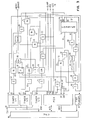
- the printer system control includes a microprocessor unit MPU 10 connected by dedicated address and data busses 11 and 12 to programmable timers PTM 1 and PTM 2 and a peripheral interface adapter PIA as well as to data communications adapter DCA 13.
- Address and data busses 11 and 12 also connect MPU 10 to ROS 14 where the microcode resides for all processing procedures performed by MPU 10 including receiving printing und control data from a host system to be stored in a random access memory RAM 15.
- MPU 10 accesses RAM 15 for storage and retrieval of data via address selector 16 and address bus 17. Data is retrieved from RAM 15 on DATA BUS 18 connected through Tri-State Device 19 to Data Bus 12.
- MPU decode 20 Also connected to the dedicated address bus 11 is MPU decode 20 which generates the various gating CHIP SEL pulses for MPU 10 to selectively access DCA 13, RAM 15, PTM 1, PTM 2 and PIA as well as other I/O devices as more fully described in EP-A-0 033 135.
- PTM 1 is connected to the carriage control by Bus 21.
- the carriage control as seen in Fig. 2 comprises control logic 22 which includes phase sequencers 23 connected to phase drivers 24 of stepper motor 25.
- Carriage control also includes pedestal drivers 26 for the stepper motor 25.
- An emitter 27 connected to stepper motor 25 generates feedback pulses FB in known manner in the course of stepper motor rotation. As shown in Fig. 2, feedback pulses FB are sent through control logic 22 for use and connection to the system.
- PTM 2 is connected by Bus 28 to a ribbon control (not shown) which comprises ribbon drive decode and ribbon motor drivers for right and left stepper motors.
- PTM 2 supplies ribbon advance and ribbon drive degate signals to ribbon drive decode for applying phase and pedestal signals to the motors for bidirectional ribbon feeding. Further details of the ribbon drive and its operation may be seen by reference to EP-A-0033153.
- PIA is operated by MPU 10 to send and receive control signals to both carriage and ribbon drives as well as to other mechanisms including a paper clamp.
- Bus 29 contains the control and feedback lines for that purpose. As seen in Fig. 2 only those signals are shown which relate to carriage control and clamp operation.
- the clamp signal is sent through control logic 22 to paper clamp driver PCL 30 and to paper clamp coil 31.
- Stepper motor 25 is operated by a combination of control signals from PTM 1 and PIA sent through control logic 22 under direction and control of MPU 10.
- the carriage drive control comprises the combination of MPU 10, PTM 1 and portions of PIA along with assorted control logic as described.
- PTM 1 comprises three timers 1/1, 1/2 and 1/3.
- PTM 1 also includes control logic for decoding commands and addresses from MPU 10 for setting the timers. Each timer is settable on command from MPU 10 to generate a timing pulse after a selected time interval or to time an operation of the carriage drive.
- the timers are basically counters which count timing pulses from a system clock via line 32 (Fig. 3).
- interrupt request signals IRQ 3 are sent to MPU 10 for the purpose of performing various routines used for carriage drive control.
- FB pulses are received by PIA from AND 52 at PORT CB1.
- PIA decodes the feedback signals and generates a level 2 interrupt request signal IRQ 2 to MPU 10. Further details of the construction and operation of PIA may be seen by reference to the Motorola publication "The Complete Motorola Data Library", namely for the peripheral interface adapter MC 6821 at pages 1-90 et seq.
- Counter 57 This is a settable binary counter which tracks carriage movement by counting feedback FB pulses and is used for gating reset pulses and G3 to timers 1/1, 1/2 and 1/3 of PTM 1 for the purposes of controlling acceleration, velocity and speed checking and operating the stop functions.
- FB pulses are supplied to 'counter 57 from AND 52 via I 58 to counter input A.
- Counter 57 is resettable at counts of 2 or 4 by signals applied to inputs R1 and R2.
- a CLAMP signal from line PB 4 of PIA to counter input R1 blocks the counter 57 when the paper clamp has not been released and the pedestal is inactive.
- a signal at R2 via I 59 from NOR 60 limits the output of Counter 57 to a count of 4.
- NOR 60 has inputs from AND 61 connected to output QB, through I 62 to QA and to I 54 which receives a STOP DELAY signal from PIA on PB 7. NOR 60 also receives a -PED signal from line PB 6 of PIA and from output QC of counter 57.
- timers 1/1 and 1/2 operate to apply stop pulses to the carriage drive.
- Timer 1/1 after a fixed interval applies the first stop pulse 34 upon receipt of a signal at G1 through I 63 from AND 64.
- Inputs to AND 64 are from QA of Counter 57, and from QB of Counter 57 through 165.
- the third input to AND 64 is from OR 66 having inputs from the output of trigger 67 and I 68 which is connected to I 54.
- Trigger 67 is set by a STOP DELAY signal 38 from PIA on PB 7 through I 54.
- Trigger 67 is switched on by a signal from output QB (count 2) of counter 57.
- timer 1/2 After a fixed interval, timer 1/2 sends the second stop pulse 35 upon appearance of a gate signal at G2 received through I 69 from OR 70.
- a first input to OR 70 is from AND 71 which has input connections from QA and QB (count 3) of Counter 57 and from line PB 5 of PIA through I 53.
- a second input to OR 70 is from AND 72 which has inputs from line PB 5 through I 53 of PIA and from output QC of Counter 57.
- Timer 1/3 has gate G3 connected through i 73 from OR 74 which has inputs from QC (count 4) of 57 counter and PB 4 of PIA through I 75. This arrangement permits timer 1/3 to perform the specified velocity checking and other operations associated with deceleration and paper clamping.
- Tri-state funnel 41 This provides the interface to MPU 10 for reading the state of various I/O devices such as end-of-forms switch and forms hold sensors. It also provides feedback of the status of counter 57 on command from MPU 10 for comparison with FB pulse counts stored in the FB pulse counter of RAM 15 by MPU 10.
- the TSD Funnel 41 looks at the state of the binary counter 57 based on command from MPU 10. Specifically, Tri-State Funnel reads the condition of the output QA of the binary counter 57 to determine whether any FB pulses were not received i.e. missed by the MPU 10 during the period of processing another higher level interrupt.
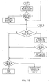
- Carriage drive control system-detailed operation Carriage Drive Operations begins with MPU 10 receiving a level 2 program interrupt request PIRR which indicates forms motion. Such interrupt may occur from various sources including the second microprocessor (not shown) in the cross- referenced EP-A-0 033 153. With this interrupt MPU 10 proceeds to the ENTER routine shown in Fig. 5 which begins with a check of the timers of PTM 1. Since none of the timers were active, MPU 10 branches immediately to the BEGIN routine in Fig. 6.
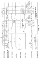
- MPU 10 In processing the BEGIN routine, MPU 10 first turns off the paper clamp. This is done by command to the PIA which drops the clamp signal 36 (see Fig. 4) on line P84 to the PCL driver 30 which de-energizes paper coil 31. MPU 10 then sets timer 1/1 to begin a four millisecond time out. This time interval permits the clamp to disengage and settle out. This operation is done by command to PTM 1 which sets a counter and GATES timing pulses on line 32 from the system clock to the timer counter.
- MPU 10 then processes the forms move quantity FMQ and line per inch LPI data which were previously stored in the MCB in RAM 15 and calculates the number of feedback pulses required for the forms move and stores the count in registers in RAM 15 indicating line count and pulses per line. If the forms move is greater than one line space, as indicated by FMQ, MPU 10 first decrements one from FMQ and stores in a line counter in the RAM register. MPU 10 then branches to the END routine in Fig. 10 which is part of the LOOP routine of Figs. 7-10.
- MPU 10 determines whether forms motion is in the deceleration phase. Since motion has not yet begun, MPU 10 proceeds to immediately reset PIRR level 2 and waits for the next interrupt request.
- the next interrupt request occurs when timer 1/1 times out after four milliseconds and sends an IRQ 3 interrupt to MPU 10.
- This interrupt is recognized by MPU 10 as a forms motion interrupt and proceeds to the ENTER routine.
- MPU 10 again checks the timers and receives a yes; and, if no errors, MPU 10 proceeds to set the pedestal and feedback gate. Both of these are done by commands sent to PIA which turns on the pedestal (PED) signal 37 and Gate feedback signal 39 (see Fig. 4).
- the pedestal signal 37 is sent through the control logic 22 to the pedestal drivers 26 of the stepper motor 25.
- MPU 10 determines the lines per inch and forms motion and sets the stop delay if motion is to be one line space to assure the proper stop. This is done by command to PIA which issues a STOP DELAY signal 38 as shown in Fig. 3. GATE feedback is set through PIA to enable PIA for receiving FB pulse interrupt requests IRQ 2 at CB 1 port. This establishes a closed loop mode of operation until FB GATE is deactivated. Such requests when received at CB 1 are recognized as level 2 interrupt requests for branching to the LOOP routine beginning at Fig. 8.
- MPU 10 then sends the first motor advance pulse and blocks FB pulses to PIA for one millisecond and proceeds to begin the acceleration check.
- the first motor advance pulse is generated by command to PTM 1 which activates timer 1/1 to generate the first motor advance pulse 33 (see Fig. 4) at terminal 01 through NOR 50 for application to the motor drivers which control the phase windings of the stepper motor 25.
- MPU 10 blocks the FB pulses for one millisecond to PIA by command to PTM 1 which sets the counter in timer 1/3 and sets a blocking signal at 03 to AND 52 in Fig. 3.
- MPU 10 begins the acceleration check by command to PTM 1 which sets the counter of timer 1/2 for a six millisecond count interval. MPU 10 having done all these then branches to the END routine and again proceeds immediately to reset PIRR level 2 to wait for additional interrupt requests.
- MPU 10 Neither timer 1/1 after generating the first motor advance pulse 33 nor timer 1/3 after the one millisecond time out will generate an interrupt request.
- the next interrupt seen by MPU 10 will be from PIA in response to the first FB pulse, after the blocking interval, applied to CB 1.
- MPU 10 upon receipt of this feedback request IRQ resets the interrupt request gate CB 1 in PIA and initiates the LOOP routine beginning in Fig. 8.
- MPU 10 updates the feedback pulse counter in RAM 15 and performs various technical operations as shown in the LOOP routine. In the course of this routine MPU 10 if acceleration is proceeding properly will have received a second FB pulse before timer 1/2 times out.
- MPU determines whether a second feedback pulse has occurred by checking the status of the line and feedback counters in RAM 15 and disables timer 1/2 as shown at 80 in Fig. 8 thereby terminating the acceleration check and preventing the generation of an IRQ 3 by timer 1/2.
- MPU 10 then checks the forms motion FMQ counter in RAM to determine if it is greater than 2. If so, it then proceeds to set timers 1/2 and 1/3 for performing the velocity checks. Should the timer 1/2 generate an interrupt request after the six millisecond time out having not been disabled by MPU 10, MPU 10 ceases further processing of the LOOP routine and proceeds to the ENTER routine where the timers are again checked. In this event, a check of timer 2 indicates an error since no interrupt request was expected and MPU 10 then proceeds to stop the carriage and identify and flag the error.
- MPU 10 continuously monitors the status of its feedback count register in RAM 15. When the feedback pulse count is less than 6 as shown at 81 in Fig. 9 MPU 10 enables the timer 1/1 to generate the first clock stop pulse to begin deceleration. This is done by command to PTM 1 to count system pulses for 1.8 milliseconds after 7ffl-has been activated by counter 57 outputs QA and QB through AND 64 as shown in Fig. 4. MPU 10 then checks its pulse counter for less than five feedback pulses then sets the paper clamp and the 8 millisecond time out and resets STOP DELAY.
- MPU 10 deactivates the GATE feedback to PIA to terminate closed loop operation and then sets timer 1/2 to count clock pulses for a 2.2 milliseconds interval after T2-has been activated by counter 57 through AND 71 to generate the second stop pulse 35. MPU 10 then proceeds with the END routine which enables PIA GATE CB 2 and disables CB 1 for the last stop pulse. When the last stop pulse 35 has been sent, MPU 10 enables timer 1/2 for a 1 millisecond pedestal detent. MPU 10 then checks for missing feedback pulse. If none, MPU 10 resets PIRR to level 2 and waits for the interrupt from timer 1/2 after the 1 millisecond time out. Upon receipt of the 1 millisecond time out from timer 1/2 MPU 10 then proceeds through the ENTER routine which ends up in a branch to the CLAMP routine.
- MPU 10 in the CLAMP routine sets a flag for the 8 millisecond paper clamp time complete, checks for carriage motion and, if yes enables a 2 millisecond deceleration check timer. This is done by setting timer 1/3 to gate clock pulses for a 2 millisecond time interval. This meets the constraint for a maximum of ten milliseconds for carriage to come to a complete stop. An interrupt from timer 1/3 afterthis interval indicates an error in ENTER routine which stops carriage and flags error. MPU 10 then proceeds to the END routine and resets PIRR level 2 if no missing pulse was detected.
- timer 1/2 At the end of the 1 millisecond Pedestal detent time out, timer 1/2 generates an IRQ 3 interrupt, checks the timers and proceeds to branch to the PED routine of Fig. 7.
- the END routine in all cases involves checking for a missed feedback pulse. Such an occurrence might happen where MPU 10 has received a feedback pulse from PIA but because of a higher priority or a lower preemptive priority interrupt did not decrement its feedback pulse counter in RAM. In that case, MPU 10 branches to LOOP and processes any pending interrupt request.
- the routine for correcting for missed feedback pulses is to check the feedback counter in RAM 15 with counter 57 as shown in Fig. 8, and decrementing the counter in RAM to correct for a missed feedback pulse.
- the feedback pulse counter is compared with the binary counter 57 again to determine whether a second feedback pulse was missed.
- MPU 10 proceeds with resetting PIRR level 2. If more than one pulse had been missed, MPU 10 will still detect a missed feedback pulse and will branch to LOOP to process the pending IRQ at which time the feedback pulse counter in RAM 15 will be decremented an additional amount to correct for the missed second pulse.
- carriage control will proceed without disturbance notwithstanding the fact that the MPU 10 was prevented from monitoring the carriage control in accordance with its normal processing routine.
Landscapes
- Character Spaces And Line Spaces In Printers (AREA)
- Record Information Processing For Printing (AREA)
- Accessory Devices And Overall Control Thereof (AREA)
Claims (7)
Applications Claiming Priority (2)
| Application Number | Priority Date | Filing Date | Title |
|---|---|---|---|
| US115850 | 1980-01-28 | ||
| US06/115,850 US4277191A (en) | 1980-01-28 | 1980-01-28 | Printer system having microprocessor control |
Publications (3)
| Publication Number | Publication Date |
|---|---|
| EP0033101A2 EP0033101A2 (fr) | 1981-08-05 |
| EP0033101A3 EP0033101A3 (en) | 1983-07-27 |
| EP0033101B1 true EP0033101B1 (fr) | 1986-05-07 |
Family
ID=22363771
Family Applications (1)
| Application Number | Title | Priority Date | Filing Date |
|---|---|---|---|
| EP81100297A Expired EP0033101B1 (fr) | 1980-01-28 | 1981-01-16 | Système de commande pour opérer l'avancement du papier dans un système d'impression avec commande par microprocesseur |
Country Status (5)
| Country | Link |
|---|---|
| US (1) | US4277191A (fr) |
| EP (1) | EP0033101B1 (fr) |
| JP (1) | JPS56114039A (fr) |
| CA (1) | CA1126083A (fr) |
| DE (1) | DE3174534D1 (fr) |
Families Citing this family (13)
| Publication number | Priority date | Publication date | Assignee | Title |
|---|---|---|---|---|
| JPS5850851U (ja) * | 1981-09-25 | 1983-04-06 | カシオ計算機株式会社 | 印字位置記録装置 |
| US4460968A (en) * | 1981-10-16 | 1984-07-17 | International Business Machines Corporation | Print head motor control with stop distance compensation |
| JPS58198198A (ja) * | 1982-05-13 | 1983-11-18 | Toshiba Corp | パルスモータ制御装置 |
| US4481569A (en) * | 1982-06-24 | 1984-11-06 | Kurt Manufacturing Company, Inc. | Feedback system for robot controller |
| JPS59202537A (ja) * | 1983-05-02 | 1984-11-16 | Omron Tateisi Electronics Co | プリンタ付き電子機器の割込み制御方法 |
| US4591969A (en) * | 1983-08-11 | 1986-05-27 | International Business Machines Corporation | Microprocessor-controlled positioning system |
| US4777609A (en) * | 1985-12-11 | 1988-10-11 | International Business Machines Corporation | Print head motor control system having steady state velocity compensation |
| JPH0734685Y2 (ja) * | 1986-09-08 | 1995-08-09 | ニスカ株式会社 | プリンタ |
| FR2627312B1 (fr) * | 1988-01-29 | 1994-02-18 | Canon Kk | Enregistreur de donnees |
| US6106172A (en) * | 1998-02-24 | 2000-08-22 | Eastman Kodak Company | Method and printer utilizing a single microprocessor to modulate a printhead and implement printing functions |
| US5980139A (en) * | 1998-04-24 | 1999-11-09 | Lexmark International, Inc. | Method of speed control for imaging system including printers with intelligent options |
| US6049348A (en) * | 1998-08-31 | 2000-04-11 | Eastman Kodak Company | Programmable gearing control of a leadscrew for a printhead having a variable number of channels |
| US6830399B2 (en) * | 2003-03-14 | 2004-12-14 | Lexmark International, Inc. | Methods and systems for compensation of media indexing errors in a printing device |
Citations (1)
| Publication number | Priority date | Publication date | Assignee | Title |
|---|---|---|---|---|
| US4179932A (en) * | 1978-05-12 | 1979-12-25 | Ranger Hubert O | Supply apparatus |
Family Cites Families (9)
| Publication number | Priority date | Publication date | Assignee | Title |
|---|---|---|---|---|
| US3777128A (en) * | 1972-03-31 | 1973-12-04 | Kearney & Trecker Corp | Input data sampling scheme for computer controlled machine tools |
| US3958224A (en) * | 1973-12-12 | 1976-05-18 | International Business Machines Corporation | System for unattended printing |
| US3963110A (en) * | 1974-06-26 | 1976-06-15 | Hy Grip Products Co. | Storage magazine and sheet feeder for typing apparatus |
| JPS51130127A (en) * | 1975-05-08 | 1976-11-12 | Nippon Telegr & Teleph Corp <Ntt> | Vertical format control equipment |
| US4091911A (en) * | 1976-05-03 | 1978-05-30 | Xerox Corporation | Control apparatus for serial printer |
| US4140404A (en) * | 1976-09-23 | 1979-02-20 | Amf Incorporated | Printer for bowling score computer |
| US4153945A (en) * | 1977-06-20 | 1979-05-08 | International Business Machines Corporation | Multiplexed control subsystem for sensor based systems |
| US4146922A (en) * | 1977-08-29 | 1979-03-27 | Ncr Corporation | Constant velocity driving means |
| US4197932A (en) * | 1978-11-09 | 1980-04-15 | Leonard Mercurio | Coin chute having single multiple coin staggered aperture |
-
1980
- 1980-01-28 US US06/115,850 patent/US4277191A/en not_active Expired - Lifetime
- 1980-11-25 CA CA365,433A patent/CA1126083A/fr not_active Expired
-
1981
- 1981-01-16 EP EP81100297A patent/EP0033101B1/fr not_active Expired
- 1981-01-16 DE DE8181100297T patent/DE3174534D1/de not_active Expired
- 1981-01-23 JP JP804981A patent/JPS56114039A/ja active Granted
Patent Citations (1)
| Publication number | Priority date | Publication date | Assignee | Title |
|---|---|---|---|---|
| US4179932A (en) * | 1978-05-12 | 1979-12-25 | Ranger Hubert O | Supply apparatus |
Also Published As
| Publication number | Publication date |
|---|---|
| JPS56114039A (en) | 1981-09-08 |
| EP0033101A3 (en) | 1983-07-27 |
| CA1126083A (fr) | 1982-06-22 |
| EP0033101A2 (fr) | 1981-08-05 |
| JPS6361187B2 (fr) | 1988-11-28 |
| US4277191A (en) | 1981-07-07 |
| DE3174534D1 (en) | 1986-06-12 |
Similar Documents
| Publication | Publication Date | Title |
|---|---|---|
| EP0033101B1 (fr) | Système de commande pour opérer l'avancement du papier dans un système d'impression avec commande par microprocesseur | |
| EP0094763B1 (fr) | Dispositif de commande pour moteur pas à pas | |
| US3884339A (en) | Asynchronous serial printer | |
| US4376588A (en) | Bi-directional serial printer with look-ahead | |
| US5315398A (en) | Automatically adjustable sheet member cutting device | |
| EP0312324B1 (fr) | Imprimante | |
| EP0033153B1 (fr) | Système d'impression | |
| US5822522A (en) | System for transferring data through a communication interface using control information in request data for controlling data receiving rates independent of the CPU | |
| EP0391730A2 (fr) | Méthode et dispositif de commande d'une imprimante | |
| EP0108225B1 (fr) | Dispositif et méthode de transfert de données d'erreur d'un appareil d'enregistrement vers un ordinateur | |
| JP3301337B2 (ja) | インクジェットプリンタ | |
| JPH0470994B2 (fr) | ||
| JPS57207080A (en) | Carriage error detector | |
| JP2656954B2 (ja) | プリンタの印字ヘッド制御方法 | |
| JP2733395B2 (ja) | 駆動系制御装置 | |
| KR960016798B1 (ko) | 디지탈서보모터의 위치제어방법 및 그 장치 | |
| JP2526916Y2 (ja) | カードアクセッサ | |
| JP2598187B2 (ja) | データ通信システムにおける端末装置 | |
| JPS6385921A (ja) | プリンタ装置 | |
| JPH05278279A (ja) | プリンタ | |
| JPS62299367A (ja) | 紙送り制御方式 | |
| KR930000183B1 (ko) | 시리얼 프린터 | |
| JP2774595B2 (ja) | Cpuシステムの動作監視装置 | |
| JPH0318919A (ja) | プリンタの受信制御方式 | |
| JPS6274677A (ja) | 印字装置 |
Legal Events
| Date | Code | Title | Description |
|---|---|---|---|
| PUAI | Public reference made under article 153(3) epc to a published international application that has entered the european phase |
Free format text: ORIGINAL CODE: 0009012 |
|
| AK | Designated contracting states |
Designated state(s): DE FR GB IT |
|
| 17P | Request for examination filed |
Effective date: 19810909 |
|
| PUAL | Search report despatched |
Free format text: ORIGINAL CODE: 0009013 |
|
| AK | Designated contracting states |
Designated state(s): DE FR GB IT |
|
| GRAA | (expected) grant |
Free format text: ORIGINAL CODE: 0009210 |
|
| AK | Designated contracting states |
Kind code of ref document: B1 Designated state(s): DE FR GB IT |
|
| PG25 | Lapsed in a contracting state [announced via postgrant information from national office to epo] |
Ref country code: IT Free format text: LAPSE BECAUSE OF FAILURE TO SUBMIT A TRANSLATION OF THE DESCRIPTION OR TO PAY THE FEE WITHIN THE PRESCRIBED TIME-LIMIT;WARNING: LAPSES OF ITALIAN PATENTS WITH EFFECTIVE DATE BEFORE 2007 MAY HAVE OCCURRED AT ANY TIME BEFORE 2007. THE CORRECT EFFECTIVE DATE MAY BE DIFFERENT FROM THE ONE RECORDED. Effective date: 19860507 |
|
| REF | Corresponds to: |
Ref document number: 3174534 Country of ref document: DE Date of ref document: 19860612 |
|
| ET | Fr: translation filed | ||
| PLBE | No opposition filed within time limit |
Free format text: ORIGINAL CODE: 0009261 |
|
| STAA | Information on the status of an ep patent application or granted ep patent |
Free format text: STATUS: NO OPPOSITION FILED WITHIN TIME LIMIT |
|
| 26N | No opposition filed | ||
| PGFP | Annual fee paid to national office [announced via postgrant information from national office to epo] |
Ref country code: GB Payment date: 19901220 Year of fee payment: 11 |
|
| PGFP | Annual fee paid to national office [announced via postgrant information from national office to epo] |
Ref country code: FR Payment date: 19901227 Year of fee payment: 11 |
|
| PGFP | Annual fee paid to national office [announced via postgrant information from national office to epo] |
Ref country code: DE Payment date: 19910131 Year of fee payment: 11 |
|
| PG25 | Lapsed in a contracting state [announced via postgrant information from national office to epo] |
Ref country code: GB Effective date: 19920116 |
|
| GBPC | Gb: european patent ceased through non-payment of renewal fee | ||
| PG25 | Lapsed in a contracting state [announced via postgrant information from national office to epo] |
Ref country code: FR Effective date: 19920930 |
|
| PG25 | Lapsed in a contracting state [announced via postgrant information from national office to epo] |
Ref country code: DE Effective date: 19921001 |
|
| REG | Reference to a national code |
Ref country code: FR Ref legal event code: ST |