EP0033228B1 - Système de commande industriel - Google Patents
Système de commande industriel Download PDFInfo
- Publication number
- EP0033228B1 EP0033228B1 EP81300292A EP81300292A EP0033228B1 EP 0033228 B1 EP0033228 B1 EP 0033228B1 EP 81300292 A EP81300292 A EP 81300292A EP 81300292 A EP81300292 A EP 81300292A EP 0033228 B1 EP0033228 B1 EP 0033228B1
- Authority
- EP
- European Patent Office
- Prior art keywords
- remote
- communications link
- control
- master
- supervisory control
- Prior art date
- Legal status (The legal status is an assumption and is not a legal conclusion. Google has not performed a legal analysis and makes no representation as to the accuracy of the status listed.)
- Expired
Links
Images


Classifications
-
- H—ELECTRICITY
- H04—ELECTRIC COMMUNICATION TECHNIQUE
- H04L—TRANSMISSION OF DIGITAL INFORMATION, e.g. TELEGRAPHIC COMMUNICATION
- H04L12/00—Data switching networks
- H04L12/28—Data switching networks characterised by path configuration, e.g. LAN [Local Area Networks] or WAN [Wide Area Networks]
- H04L12/40—Bus networks
- H04L12/40169—Flexible bus arrangements
- H04L12/40176—Flexible bus arrangements involving redundancy
- H04L12/40195—Flexible bus arrangements involving redundancy by using a plurality of nodes
-
- G—PHYSICS
- G05—CONTROLLING; REGULATING
- G05B—CONTROL OR REGULATING SYSTEMS IN GENERAL; FUNCTIONAL ELEMENTS OF SUCH SYSTEMS; MONITORING OR TESTING ARRANGEMENTS FOR SUCH SYSTEMS OR ELEMENTS
- G05B19/00—Program-control systems
- G05B19/02—Program-control systems electric
- G05B19/04—Program control other than numerical control, i.e. in sequence controllers or logic controllers
- G05B19/042—Program control other than numerical control, i.e. in sequence controllers or logic controllers using digital processors
- G05B19/0428—Safety, monitoring
-
- G—PHYSICS
- G06—COMPUTING OR CALCULATING; COUNTING
- G06F—ELECTRIC DIGITAL DATA PROCESSING
- G06F11/00—Error detection; Error correction; Monitoring
- G06F11/07—Responding to the occurrence of a fault, e.g. fault tolerance
- G06F11/16—Error detection or correction of the data by redundancy in hardware
- G06F11/20—Error detection or correction of the data by redundancy in hardware using active fault-masking, e.g. by switching out faulty elements or by switching in spare elements
- G06F11/202—Error detection or correction of the data by redundancy in hardware using active fault-masking, e.g. by switching out faulty elements or by switching in spare elements where processing functionality is redundant
- G06F11/2023—Failover techniques
- G06F11/2025—Failover techniques using centralised failover control functionality
-
- G—PHYSICS
- G06—COMPUTING OR CALCULATING; COUNTING
- G06F—ELECTRIC DIGITAL DATA PROCESSING
- G06F11/00—Error detection; Error correction; Monitoring
- G06F11/07—Responding to the occurrence of a fault, e.g. fault tolerance
- G06F11/16—Error detection or correction of the data by redundancy in hardware
- G06F11/20—Error detection or correction of the data by redundancy in hardware using active fault-masking, e.g. by switching out faulty elements or by switching in spare elements
- G06F11/202—Error detection or correction of the data by redundancy in hardware using active fault-masking, e.g. by switching out faulty elements or by switching in spare elements where processing functionality is redundant
- G06F11/2041—Error detection or correction of the data by redundancy in hardware using active fault-masking, e.g. by switching out faulty elements or by switching in spare elements where processing functionality is redundant with more than one idle spare processing component
-
- G—PHYSICS
- G06—COMPUTING OR CALCULATING; COUNTING
- G06F—ELECTRIC DIGITAL DATA PROCESSING
- G06F11/00—Error detection; Error correction; Monitoring
- G06F11/22—Detection or location of defective computer hardware by testing during standby operation or during idle time, e.g. start-up testing
-
- H—ELECTRICITY
- H04—ELECTRIC COMMUNICATION TECHNIQUE
- H04B—TRANSMISSION
- H04B17/00—Monitoring; Testing
- H04B17/40—Monitoring; Testing of relay systems
-
- H—ELECTRICITY
- H04—ELECTRIC COMMUNICATION TECHNIQUE
- H04L—TRANSMISSION OF DIGITAL INFORMATION, e.g. TELEGRAPHIC COMMUNICATION
- H04L1/00—Arrangements for detecting or preventing errors in the information received
-
- H—ELECTRICITY
- H04—ELECTRIC COMMUNICATION TECHNIQUE
- H04L—TRANSMISSION OF DIGITAL INFORMATION, e.g. TELEGRAPHIC COMMUNICATION
- H04L1/00—Arrangements for detecting or preventing errors in the information received
- H04L1/12—Arrangements for detecting or preventing errors in the information received by using return channel
- H04L1/16—Arrangements for detecting or preventing errors in the information received by using return channel in which the return channel carries supervisory signals, e.g. repetition request signals
- H04L1/1607—Details of the supervisory signal
- H04L1/1628—List acknowledgements, i.e. the acknowledgement message consisting of a list of identifiers, e.g. of sequence numbers
-
- H—ELECTRICITY
- H04—ELECTRIC COMMUNICATION TECHNIQUE
- H04L—TRANSMISSION OF DIGITAL INFORMATION, e.g. TELEGRAPHIC COMMUNICATION
- H04L1/00—Arrangements for detecting or preventing errors in the information received
- H04L1/24—Testing correct operation
- H04L1/242—Testing correct operation by comparing a transmitted test signal with a locally generated replica
- H04L1/243—Testing correct operation by comparing a transmitted test signal with a locally generated replica at the transmitter, using a loop-back
-
- H—ELECTRICITY
- H04—ELECTRIC COMMUNICATION TECHNIQUE
- H04L—TRANSMISSION OF DIGITAL INFORMATION, e.g. TELEGRAPHIC COMMUNICATION
- H04L12/00—Data switching networks
- H04L12/28—Data switching networks characterised by path configuration, e.g. LAN [Local Area Networks] or WAN [Wide Area Networks]
- H04L12/40—Bus networks
- H04L12/407—Bus networks with decentralised control
- H04L12/417—Bus networks with decentralised control with deterministic access, e.g. token passing
-
- G—PHYSICS
- G05—CONTROLLING; REGULATING
- G05B—CONTROL OR REGULATING SYSTEMS IN GENERAL; FUNCTIONAL ELEMENTS OF SUCH SYSTEMS; MONITORING OR TESTING ARRANGEMENTS FOR SUCH SYSTEMS OR ELEMENTS
- G05B2219/00—Program-control systems
- G05B2219/20—Pc systems
- G05B2219/25—Pc structure of the system
- G05B2219/25154—Detect error, repeat transmission on error, retransmit
-
- G—PHYSICS
- G05—CONTROLLING; REGULATING
- G05B—CONTROL OR REGULATING SYSTEMS IN GENERAL; FUNCTIONAL ELEMENTS OF SUCH SYSTEMS; MONITORING OR TESTING ARRANGEMENTS FOR SUCH SYSTEMS OR ELEMENTS
- G05B2219/00—Program-control systems
- G05B2219/20—Pc systems
- G05B2219/25—Pc structure of the system
- G05B2219/25161—Only receiving station, read several times message, select correct one or reject
-
- G—PHYSICS
- G05—CONTROLLING; REGULATING
- G05B—CONTROL OR REGULATING SYSTEMS IN GENERAL; FUNCTIONAL ELEMENTS OF SUCH SYSTEMS; MONITORING OR TESTING ARRANGEMENTS FOR SUCH SYSTEMS OR ELEMENTS
- G05B2219/00—Program-control systems
- G05B2219/20—Pc systems
- G05B2219/25—Pc structure of the system
- G05B2219/25163—Transmit twice, redundant, same data on different channels, check each channel
-
- G—PHYSICS
- G06—COMPUTING OR CALCULATING; COUNTING
- G06F—ELECTRIC DIGITAL DATA PROCESSING
- G06F11/00—Error detection; Error correction; Monitoring
- G06F11/22—Detection or location of defective computer hardware by testing during standby operation or during idle time, e.g. start-up testing
- G06F11/2205—Detection or location of defective computer hardware by testing during standby operation or during idle time, e.g. start-up testing using arrangements specific to the hardware being tested
-
- G—PHYSICS
- G06—COMPUTING OR CALCULATING; COUNTING
- G06F—ELECTRIC DIGITAL DATA PROCESSING
- G06F11/00—Error detection; Error correction; Monitoring
- G06F11/22—Detection or location of defective computer hardware by testing during standby operation or during idle time, e.g. start-up testing
- G06F11/2294—Detection or location of defective computer hardware by testing during standby operation or during idle time, e.g. start-up testing by remote test
-
- H—ELECTRICITY
- H04—ELECTRIC COMMUNICATION TECHNIQUE
- H04L—TRANSMISSION OF DIGITAL INFORMATION, e.g. TELEGRAPHIC COMMUNICATION
- H04L12/00—Data switching networks
- H04L12/28—Data switching networks characterised by path configuration, e.g. LAN [Local Area Networks] or WAN [Wide Area Networks]
- H04L12/40—Bus networks
- H04L2012/4026—Bus for use in automation systems
Definitions
- the present invention relates to a method of operating a control system as in the first part of Claim 1 and to a control system as in the first part of Claim 4.
- remotes Such methods and such systems are known in which a set of remotely located process control units, which are referred to in the description hereinafter as "remotes", are each capable of assuming control of the communications link to which they are all connected so as to enable the units to communicate freely between one another.
- the remotes are organised into a hierarchical system whereby each in turn has the opportunity to become the master for the moment and each has a respective timer and that when control is to be transferred to the next master for the moment a related timing period is commenced in which the transfer is to be completed. Should the timing means time out, which will happen should the master-to-be have failed to have accepted control by the end of the timing period, control is then automatically denied to that remote and offered to another.
- the control of the system is assumed by the highest priority remote and the sequence of operation in the system restarts.
- the timing means of the respective remotes are in fact fixed length timers and the duration of the timing period of each is chosen so that it reflects the order of the respective remote in the hierarchy with the highest priority remote having the shortest time-out interval.
- a second timer in each remote sets a time interval TB at the time the remote transmits its transfer command signal SEL. If the next station does not accept the transfer the present station adds one to the address and re-transmits the transfer command signal SEL to the second successive remote.
- This alternative system still suffers the disadvantage that it depends upon the proper functioning of the present master. Should the present master fail, then once again the highest priority station will automatically become the new master.
- the present invention differs from these arrangements in that in the event of a timing-out occurring, control is offered to a succeeding remote and to facilitate such operation each remote is equipped with a variable period timer.
- each remote is equipped with a variable period timer.
- the remotes which are to succeed the new master-to-be all have their timers set to provide a respective selected number of timing increments, these timing increments each being of common fixed length but the number being dependent upon the order of the remotes in the hierarchal system relative to the present master.
- the remote succeeding the next master-to-be has its timer set to, say, 50 microseconds
- the remote succeeding the next succeeding remote has its timer set at this same instant to 100 microseconds
- the third succeeding remote at this same instant has its timer set to 150 microseconds, and so on, irrespective of the actual location of these remotes in the hierarchal system.
- the system is, moreover, arranged so that the selection of the masters rotates in a cyclic sequence through all the remote stations even in the event of a malfunction. Known systems do not have this capability.
- An industrial control system is shown in schematic form in Fig. 1 and includes a communications link CL (C-link) having a plurality of remotely located process control units (remotes) R 1 , R 2 , ... R 7 , R s connected thereto with the eight remotes (R 1 -R 8 ) shown being exemplary; it being understood that the system is designed to be used with a much larger number of remotes.
- the remotes R,-R 3 and R 5 ⁇ R 7 are 'primary' remotes and the remotes R 4 and R 8 are 'redundant' remotes.
- the communications link CL is shown as an open line, double channel configuration formed from dual coat, dual twisted pair, or the like with the individual communication links identified, respectively, by the reference characters CL0 and CL1. While the system configuration shown in Fig. 1 is a distributed open loop or shared global bus type, the invention is equally suitable for application to central systems or central/distributed hybrid configurations.
- the system of Fig. 1 is adapted for use in controlling an industrial process, e.g., the operation of a power generating plant, with each primary remote unit R,-R 3 and R 5 ⁇ R 7 connected to one or more associated or corresponding input/output devices I/O 1 -I/O 3 and I/O 5 ⁇ I/O 7 , respectively.
- Each input/output device is, in turn, connected to an associated controlled device CD,-CD 3 and CD 5 ⁇ CD 7 (of which only CD 6 and CD 7 are illustrated in Fig. 1) such as, but not limited to, various types of sensors (temperature, pressure, position, and motion sensors, etc.) and various types of actuators (motors, pumps, compressors, valves, solenoids, and relays, etc.).
- Each primary remote may control a large number of output devices and respond to a large number of input devices, and the blocks labeled I/0 in Fig. 1 can each represent many input and output devices.
- the redundant remote R 4 monitors the operation of primary remotes R i , R 2 , and R 3 ; and the redundant remote R 8 monitors the operation of primary remotes R 5 , R 6 , and R 7 .
- the failure will be detected by the remote R 4 in a manner to be described and the remote R 4 will take over control of the input and output devices of the failed remote by receiving the data from the failed remote over the communications link CL and sending commands to the failed remote over the communications link CL in formated information blocks.
- the redundant remote R s will take over control of the operation of the input/output devices for the failed remote as described above with respect to redundant remote R 4 .
- the architecture of an exemplary remote R n is shown in Fig. 2. Whle the architecture of the remote R n can vary depending upon the control process requirements, the remote shown in Fig. 2 includes a modem 10; a communication protocol controller 12; an input/output management device 14; a central processing unit (CPU) 16; a memory 18; a peripheral device 20 that can include, e.g., a CRT display, a printer, or a keyboard; and a common bus 22 which provides addressing, control, and information transfer between the various devices which constitute the remote.
- the devices shown in dotted line illustration in Fig. 2 that is, the central processing unit 16, the memory 18, and the peripheral device 20) are provided depending upon the process control requirements for the remote R n .
- the appropriate peripheral device(s) 20 may be connected to the common buss 22.
- the modem 10 provides two independent communication channels CH0 and CH1 connected, respectively, to the communication links CL0 and CL1.
- Each of the communication channels CH0 and CH1 is provided with substantially identical communication devices, and a description of the communication devices of the first communication channel CH0 is sufficient to provide an understanding of the second communication channel CH1.
- the communication channel CH0 includes an encoder/decoder 24 0 for providing appropriate modulation and demodulation of the digital data transmitted to and received from the communication link CLO.
- the encoder/decoder 24 0 converts digital information in non-return-to-zero binary (NRZ) format to base-band modulation (BBM) signal format for transmission and effects the converse for reception.
- NRZ non-return-to-zero binary
- BBM base-band modulation
- Amplifiers 26 0 and 28 0 are provided, respectively, to drive a passive coupling transformer T0 with digital information provided from the encoder/decoder 24 0 from the coupling transformer T ⁇ .
- a set of selectively operable relay contacts 30 0 are provided between the coupling transformer T0 and the corresponding communication link CL0 to effect selective interruption thereof to isolate the remote R n from the communications link CL, and another set of relay contacts 32 0 are provided to selectively connect the signal output of the coupling transformer T ⁇ with a termination impedance Z0.
- the termination impedance Z0 is used when the particular remote R n is at the end of the communication link CL to provide proper line termination impedance for the link, or, as described in more detail below, to assist in terminating an open or degraded portion of the communications link CL.
- a selectively operable loop-back circuit 34 is provided to permit looping back or recirculation of test data during diagnostic checking of the remote R n . While not specifically shown in Fig. 3, the loop-back circuit 34 can take the form of a double pole, single throw relay that effects connection between the channels CH0 and CH1 in response to a loop-back command signal 'LB'.
- the relay contacts of the loop-back circuit 34 are closed and a predetermined test word is sent from the channel CH0 to the channel CH1 and from the channel CH1 to the channel CH0 with the received word in each case being checked against the original test word to verify the transmit/ receive integrity of the particular remote.
- the isolation relays 30 0 and 31 1 , the impedance termination relays 32 0 and 32 1 , and the loop-back circuit 34 are connected to and selectively controlled by a communications link control device 38 which receives its communication and control signals from the communications protocol controller 12 described more fully below.
- a watch-dog timer 40 is provided to cause the C-link control device 38 to operate the isolation relays 30 0 and 30 1 to disconnect the remote R n from the communication link CL in the event the time 40 times-out.
- the timer 40 is normally prevented from timing out by periodic reset signals provided from the communication protocol controller 12. In this way, a remote R n is automatically disconnected from the communication link CL in the event of a failure of its communication protocol controller 12.
- each communication protocol controller 12 includes input/output ports 42, 44, and 46 which interface with the above described modem 10 for the communication channels CH0 and CH1 and the modem C-link control device 38 (Fig. 3).
- a first-in first-out (FIFO) serializer 48 and another first-in first-out serializer 50 are connected between the input/output ports 42 and 44 and a CPU signal processor 52.
- the first-in first-out serializers 48 and 50 function as temporary stores for storing information blocks provided to and from the modems 10 as described more fully below.
- the CPU 52 interfaces with the buss 22 through buss control latches 54.
- a read only memory (ROM) 56 containing a resident firmware program for the CPU 52 and a random access memory (RAM) 58 are provided to permit the CPU 52 to effect its communication protocol function as described more fully below.
- Timers 62 and a register 60 (for example, a manually operable DIP switch register or a hardwired jumper-type register) that includes registers 60a and 60b are also provided to assist the CPU 52 in performing its communication protocol operation.
- An excess transmission detector 64 connected to input/ output ports 42 and 44 (corresponding to communication channels CH0 and CH1) determines when the transmission period is in excess of a predetermined limit to cause the C-link control device 38 (Fig. 3) to disconnect the transmitting remote from the communications link CL and thereby prevent a remote that is trapped in a transmission mode from monopolizing the communications link CL.
- the input/output management device 14 is preferably a firmware controlled microprocessor- based device which is adapted to scan the various input/output hardware points of the controlled device, effect a point-by-point status comparison with a prior scan, and record the change-in-status events along with the direction of the change and the time the event occurred (time-tagging), effect data collection and distribution to and from the input/output points, format the collected data in preferred patterns, and assemble the patterned data in selected sequences.
- a firmware controlled microprocessor- based device which is adapted to scan the various input/output hardware points of the controlled device, effect a point-by-point status comparison with a prior scan, and record the change-in-status events along with the direction of the change and the time the event occurred (time-tagging), effect data collection and distribution to and from the input/output points, format the collected data in preferred patterns, and assemble the patterned data in selected sequences.
- the input/output management device 14 includes a processor 14A connected to the remote buss 22 through a processor buss 14B; read-only-memories 14C and 14D connected to the processor 14A through appropriate connections with these memories including the firmware necessary to effect the above-described functions of the input/output management device 14 including the change-in-status event monitoring (described in more detail below); a read/write memory 14E (RAM) for temporarily storing information incident to the operation of the processor 14A including the change-in-status event information; a time base 14F for providing time information for time tagging the change-in-status events; and an input/output interface 14G for connection, either directly or indirectly, to the controlled devices.
- a processor 14A connected to the remote buss 22 through a processor buss 14B
- read-only-memories 14C and 14D connected to the processor 14A through appropriate connections with these memories including the firmware necessary to effect the above-described functions of the input/output management device 14 including the change-in-status event monitoring
- the input/output interface 14G is defined by one or more printed circuit control cards generally arranged in rack formation with each card having hardware points arranged in predetermined sets of eight points with each hardware point carrying a binary indication for controlling or sensing the operation of the controlled device.
- the control and operational status of the controlled device can generally be represented by one or more eight-bit words (e.g., 00010001) with each bit position representing a control or operational characteristic of the controlled device.
- the input/output management device 14 effects the aforedescribed change-in-status monitoring and associated time-tagging by periodically scanning the input/output hardware points in eight-bit groups and effecting a comparison between the so-obtained eight-bit group and the eight-bit group obtained during the previous scan. If a change is detected in one or more of the bit positions, the latest eight-bit group, along with the time-of-day information obtained from the time base 14F, and other information, if desired, representing the direction of change, is placed in a first-in first-discard memory (FIFO) of predetermined size.
- FIFO first-in first-discard memory
- the memory loading is inhibited by the occurrence of any one of a selected number of inhibit signals.
- various conditions including alarm conditions which represent partial or full system failures can be assigned a priority with those conditions or combinations thereof designated as "high" priority signals being permitted to disable or inhibit further accessing of the memory.
- the memory is inhibited from storing additional change-in-status information and the change-in-status events occurring prior to the high priority condition are preserved for subsequent analysis.
- Alarm conditions which are not designated as high priority do not inhibit the memory.
- This technique advantageously differs from those prior techniques in which the controlled device status was only placed in memory at the moment of a high priority signal (in which case a historical pre-failure record-of- events was not available) or those techniques in which the change-in-status events were logged in a memory which was periodically cleared, refilled, and cleared in which case the probability of obtaining a complete history of events prior to a predetermined high priority condition diminished in those instances in which the logging memory was cleared just prior to the occurrence of the high priority condition.
- Fig. 4B The manner by which the input/output management device 14 effects the change-of-status event logging is shown in Fig. 4B.
- the processor 14B (referred to also as the RTZ in Fig. 4B) moves an image of the various input/output points, that is, the current status of the various input/output hardware points, to preassigned locations in the memory 14E (local) of the input/output management device 14 and the memory 18 (system) of the remote R n (Fig. 2).
- the address(s) of the first input/output card is obtained and the input/output hardware points for that card are scanned to obtain an input/output image which takes the form of an eight-bit word (e.g., 00000000) with each bit position representing the control or operational status of the controlled device.
- the input/output points so obtained are then compared with the previously obtained image of the points (e.g., 00100000), for example, by effecting a bit-by-bit exclusive OR (XOR) comparison. If the comparison indicates no change in status, (that is, the words are identical) the input/output points in the remaining cards are likewise scanned with the process repeated on a cyclic or looped basis.
- XOR exclusive OR
- the first-in first discard memory may be configured by assigning a preselected number of memory locations in the memory 18 of the remote R n (e.g., fifty locations) for the logging information and providing an address pointer that points to each successive location in a serial manner with the pointer returning to the first location after pointing at the last available pre-assigned location in the memory.
- a preselected number of memory locations in the memory 18 of the remote R n e.g., fifty locations
- the processor 14A of the input/output management device 14 (Fig. 4A) and the processor 52 (Fig. 4) of the communication protocol controller 12 is 8x300 micro-controller manufactured by the Signetics Company of Sunnyvale, California, and the central processing unit 16 (Fig. 2) is an 86/12 single board 16-bit micro-computer manufactured by the Intel Company of Santa Clara, California and adapted to and configured for the Intel "MULTIBUS".
- Each remote R n is adapted to communicate with the other by transmitting digital data organized in predetermined block formats.
- a suitable and illustrative block format 66 is shown in Fig. 5 and includes a multi-word header frame 66A, a multi-word data frame 66B, and a block termination frame or word 66C. Selected of the information block configurations are adapted to transfer process control information to and from selected remote units R n and other of the block configurations are adapted to transfer supervisory control of the communications link CL from one remote to the other remote as explained in greater detail below.
- the header frame 66A preferably includes a 'start of header' word(s) that indicates to all remotes that information is being transmitted; a 'source' identification word(s) that indicates the identity of the source remote R s that is transferring the information; a 'destination' word(s) that indicates the identity of the receiving or destination remote R d ; a 'header- type' word(s) that indicates whether the data block is transferring data, a parametered command block, or a parameterless command block; 'block-type' word indicating the type of block (that is, a command block or a data block); a 'block number' word that indicates the number of blocks being sent; a 'block size' word indicating the length of the data frame; a 'security code' word(s) that permits alteration of the resident software programming in a remote; and, finally, a two-byte
- the data frame for each data block can include a plurality of data carrying bytes or words B 1 , B 2 , ... B n of variable length terminated with a two-byte cyclic redundancy code word.
- each of the remotes is adapted to acknowledge (ACK) successful receipt of data and command blocks and non-acknowledge (NAK) the receipt of data in which a transmission error is detected.
- ACK acknowledge
- NAK non-acknowledge
- the header format used is shown in Figs. 5C and 5D in which an acknowledgement (ACK) or non-acknowledgement (NAK) word occupies the 'block type' word position.
- ACK acknowledgement
- NAK non-acknowledgement
- the various remote units R 1 , R 2 , R 3 , ... R n communicate with one another by having each remote successively take control of the communications link CL and the controlling remote R s then sending digital information between itself and a destination remote R d using a double transmission alternate line technique that provides for high reliability data transfer between remotes even when one of the two communication links CL0 or CL1 is inoperative, for example, when one of the two communication cables is severed or otherwise degraded as occasionally occurs in harsh industrial environments.
- a remote unit assumes control of the communication link CL (as explained more fully below) and, as a source remote R s , desires to send data blocks to another, destination remote R d , the data block is assembled at the source remote R s in accordance with the block formats discussed above in connection with Figs. 5-5D and transmitted through the information channels CL0 and CL1 of the source remote R s to the communication links CL0 and CL1 with the header frame containing both the source remote R s and the destination remote R d identification information.
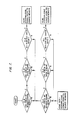
- the communication protocol controller 12 of the source remote R s transmits the information blocks twice on each communication link CL0 and CL1 as schematically illustrated in Fig. 6 to provide a first data block DB A and then a second, following data block DB B on each communication link CL0 and CL1.
- the transmitted information block headers include the identity of the destination remote, R d , which causes the destination remote R d to receive and act upon the information blocks.
- the two data blocks DB AO and DB BO on the communication link CL0 are passed through the communication channel CH0 and the two data blocks DB A , and DB B1 , on the communication link CL1 are passed through the communication channel CH1 to, respectively, the first-in first-out serializers 48 and 50 (Fig. 4).
- the destination remote R d checks the validity of the received data by selecting one of the two communication links (e.g., CL0 in Fig. 7) and then checks the first data block on the selected line (that is, DB A0 ) by performing a cyclic redundancy check of the header frame and, if valid, performing a cyclic redundancy check of the data frame. If the data frame is valid, the communication protocol controller 12 of the destination remote R d then performs a bit-for-bit comparison between the CRC-valid first data block DB AO and the second following data block DB B0 .
- an acknowledgement (ACK) signal is sent from the destination remote R d to the source remote R s to indicate the receipt of valid information and complete that data block information transaction.
- the protocol controller 12 of the destination remote R d selects the other, alternate line (in this case, CL1) and performs the aforementioned cyclic redundancy checks of the header and data frame and the bit-for-bit comparison between the first and second data blocks DB A1 and DB B1 , on the alternate line CL1.
- the destination remote R d responds with an acknowledgement signal (ACK) to conclude the data block transmission transaction.
- ACK acknowledgement signal
- the destination remote R d responds with a non-acknowledgement signal (NAK) to cause retransmission of the data blocks from the source remote R s .
- NAK non-acknowledgement signal
- the non-acknowledgement block NAK includes a byte or bytes indicating the identity of the data block or blocks which should be retransmitted.
- a counter (not shown) is provided that counts the number of retransmissions from the source remote R s and, after a finite number of retransmissions (e.g., four), halts further retransmission to assure that a source remote R s and a destination remote R d do not become lost in a repetitive transmit/NAK/ retransmit/NAK ... sequence in the event of a hardware or software failure of the destination remote R d error checking mechanism.
- a finite number of retransmissions e.g., four
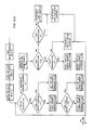
- the double message alternate line checking sequence summarized in Fig. 7 may be more fully appreciated by referring to the detailed flow diagram shown in Figs.. 8A and 8B (as read in accordance with the flow diagram map of Fig. 9).
- the line 0-first' flag register is checked; if a flag is present, the 'first-attempt fail' flag register is checked, and, if there is no flag in this register, the two data blocks DB A , and DB B1 on channel CH1 are stored while the two data blocks DB A0 and DB B0 one channel CH0 are used for the first attempt information check.
- the header frame of the first data block DB A0 on channel CH0 undergoes a CRC check, and, if acceptable, the data frame of this data block DB A0 undergoes a CRC check. If the header and data frames CRC checks indicate valid data a 'good message' register is incremented. If the number of good messages is less than two, the error checking procedure returns to the initial part of the flow diagram and, after determining there is no channel CH0 first flag or first-attempt flag present, checks the second following data block DB B0 by repeating the header and data CRC cyclic redundancy checks.
- the 'good message' register is incremented again to indicate that a total of two messages in succession (that is, DB A0 and DB BO ) have passed the cyclic redundancy check for the header and data frames.
- the two data blocks DB AO and DB B0 received on line CH0 are checked by performing a bit-by-bit comparison between the two. If the data blocks DB AO and DB B0 pass the bit-by-bit comparison test, the communications protocol controller 12 of the destination remote R d sends an acknowledgement (ACK) message to the source remote R s to conclude the information block transfer and resets the various registers.
- ACK acknowledgement
- the communication protocol controller 12 sets the 'first-attempt fail' flag and returns to the start of the procedure to determine that the 'line 0-first' flag and the 'first-attempt' fail flag are present.
- the communication protocol controller 12 uses the stored data blocks DB A1 and DB B1 , from line CL1 (which data blocks were previously stored in FIFO 50).
- the header block and data block of the data blocks DB A1 and DB B1 from line CL1 undergo the CRC check and, if successful, cause the incrementing of the 'good message' register to cause the communication protocol controller 12 to then check the validity of the second data block DB B1 . If the data blocks DB A1 , and DB B1 , pass the CRC checks, they are compared with one another in a bit-by-bit comparison test and if this comparison check is successful, an acknowledgement (ACK) is sent.
- ACK acknowledgement
- a non-acknowledgement is sent to the source remote R s including information requesting the retransmission of the data blocks which failed the validity test at the destination remote R d .
- the source remote R s then retransmits the improperly received information blocks as described above with retransmission limited to a finite number.
- a register is provided for each of the communication links for recording, in a cumulative manner, the number of times an invalid message is received for each communication link. In this manner, it can be determined, on a statistical basis, whether one of the two communiction links has suffered a deterioration in signal transmission capability and, of course, whether one of the communication links is severed.
- the dual transmission of the identical messages on plural communication links vastly enhances the ability of the destination remote R d to detect errors and determine whether the information being transmitted is valid or not.
- the destination remote R d is able to operate and successfully receive messages even if one of the communication links CL0 or CL1 is severed since the communication protocol controller 12 at the destination R d will examine the received signals on each line and will find invalid data on the severed line, but will always examine the data blocks on the other line and, if necessary, request retransmission of the information blocks.
- one of the two channels CH0 or CH1 for the first validity check it is preferred that one of the two channels (e.g., CH0) be selected for the first check on every other information transaction and that the other of the two channels (e.g., CH1) be selected for the first check for the other intermediate information transactions.
- the system has been disclosed as having dual communication links CL0 and CL1, the invention is not so limited and can encompass more than two communication links with the remotes adapted to sequentially examine signals received on the various channels.
- each remote R n of the control system is adapted to accept and then relinquish supervisory control of the communication link CL on a master-for-the-moment or revolving master arrangement.
- the communication protocol controller 12 of each remote R n includes a register which contains the remote succession number, another register which contains the total number of remotes in the system, and another register which contains the relative position of the remote from the present system master.
- the first two registers are schematically illustrated by the reference character 60 in Fig. 4.
- each remote R n includes a variable transfer-monitor timer having a time-out interval that is set in accordance with a predetermined control-transfer time constant (50 microseconds in the preferred embodiment) and the position of the particular remote relative to the present system master to permit, as explained in more detail below, the master-for-the-moment transfer to continue even in the event of a disabled remote (that is, a remote that is unable to accept supervisory control because of a malfunction).
- Another timer is provided to force transfer of supervisory control of the communications link CL in the event a remote, because of a malfunction, is unable to transfer supervisory control to its next successive remote.
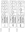
- each table indicates the succession sequence or order of the five remotes R o , R i , R 2 , R 3 and R 4 that comprise the system; the intermediate row identifies the remote that is the present master-for-the-moment and also identifies the relative successive position of the other remotes from the present master, that is, the first (or next) successive remote from the present master, the second successive remote from the present master, the third remote from the present master, etc.; and the third row of each table lists the setting of the variable transfer-monitor timer for the particular remote.
- the system is provided with initialization software so that the first remote in the succession, R o , assumes supervisory control of the communication link CL after system start-up and becomes the initial master of the system (Fig. 1 OA).
- the initial master R o When the initial master R o is in control of the communications link CL, it can send data to any of the other remotes, request status or other data from another remote, and send control blocks and the like over the communications link CL.
- the master R o determines that it no longer desires possession of the communications link CL, it passes supervisory control of the communications link CL to the next or first successive remote in accordance with the succession order.
- the present master R o when the present master R o concludes its information transfer transactions, it transfers supervisory control of the communications link CL to its next or first successive remote R, by transmitting a control block to the remote R, with all the remaining remotes (that is, R 2 , R 3 , R 4 ) being cognizant of the transfer of supervisory control from the present master R o to its first or next successive remote R,. Since, in the present system, the transfer of supervisory control of the communications link CL is expected to take place within 50 micro- seconds, the second successive remote R2, as shown in the third row of the table of Fig. 10B, sets its variable transfer-monitor timer to 50 micro-seconds, the third successive.
- the fourth successive remote R 4 sets its transfer-monitor timer to 150 micro- seconds.
- the first successive remote R receives the control block from the present master R o , it accepts supervisory control of the communications link CL by responding with an acknowledgement message (ACK). If the control block is misreceived, the first successive remote R, can respond with a non-acknowledgement (NAK) to request retransmission of the control block transferring supervisory control of the communications link CL.
- NAK non-acknowledgement
- the transfer-monitor timers of the remaining remotes are counting down.
- the transfer-monitor timer of the second successive remote R 2 will time-out at 50 micro- seconds and cause the second successive remote R 2 to then accept supervisory control of the communication link CL from the present master R o and thus bypass the apparently malfunctioning first successive remote R i .
- the present master R concludes its information transfer transactions, if any, it attempts to transfer supervisory control to its first or next successive remote R 2 by sending an appropriate control block to remote R 2 which responds with an acknowledgement signal (ACK) or, in the event of a mistransmission of the control block, a non-acknowledgement signal (NAK) which causes retransmission of the control block.
- ACK acknowledgement signal
- NAK non-acknowledgement signal
- supervisory control of the communications link CL will transfer even if one or more successive remotes are malfunctioning, when the transfer-monitor timer of the next operable remote times out.
- This transfer sequence continues in succession as shown in the remaining tables of Figs. 10D to 10F with supervisory control of the communication link CL being passed from remote to remote in succession with the last remote R 4 returning supervisory control to the first remote R o .
- a master-for-the-moment transfer technique in which the receiving remote acknowledges control from the transferring remote and in which retransmission of a misreceived control block is provided for in response to a non-acknowledgement signal from the receiving remote, it is possible to positively transfer supervisory control of the communication link.
- This technique advantageously transfers control using the data and information carrying communication link rather than, as in other systems, by providing separate communication lines or channels dedicated solely to supervisory control transfer functions.
- the provision of a variable transfer-monitor timer at each remote that is set in accordance with the remote's relative position to the present master and a transfer time-constant automatically transfers supervisory control of the communications link even if one or more of the successive remotes are malfunctioning.
- a redundant remote (R, and R 8 in Fig. 1), as shown in Fig. 11, is essentially the same as that of a primary remote except that it has no input/output devices assigned to it.
- Each redundant remote functions to take over control responsibility of a controlled device from a primary remote in the event the primary remote malfunctions.
- each primary remote preassigned memory locations are designated to act as a 'mailbox' register for that remote.
- the central processing unit 16 of the primary remote cycles through its applications program, in which it responds to and controls the input/output devices of the remote via the input/output management device 14, it stores a predetermined number in its mailbox.
- the processor 14A of the input/output management device 14 cycles through its program, it decrements the number stored in the mailbox.
- the time for the CPU 16 to cycle through its program and for the input/ output management device 14 to cycle through its program is approximately 1:1 so that the number stored in the mailbox will be maintained at or near the predetermined value set by the applications program of the CPU 16 unless the CPU 16 ceases to cycle through its applications program. Should this happen, the number stored in the mailbox memory 18 will be decremented by the input/output management device 14 until it reaches a zero value.
- the redundant remote will request and obtain the value of the number in the mailbox of its assigned primary remotes. If the number in the mailbox is not zero, the redundant remote will know that the central processing unit 16 in the so-queried primary remote is carrying out its applications program and has not gone into an emergency mode of operation or otherwise ceased to operate. If the redundant remote detects that the number in the mailbox for one of its assigned primary remotes is zero, then the redundant remote will determine that the central processing unit 16 of the zero- mailbox remote is not carrying out the applications program and, in response to this determination, the redundant remote will first attempt to restart the applications program in the central processing unit 16 of the primary remote.
- the redundant remote will carry out the applications program for the failed remote.
- the redundant remote will respond to the input devices and control the output devices assigned to the failed primary remote by sending commands and receiving data from the failed remote over the communications link CL.
- the redundant remote in addition to checking the status of its assigned primary remotes for which the redundant remote serves as a back-up, also must maintain an up-to-date record of the status of the applications program in each of these assigned primary remotes.
- the redundant remote checks the status of the mailbox and gets the current applications program status from each of the primary remotes by sending requests for information over the communications link CL when the redundant remote takes its turn in the master-for-the-moment sequence as described above.
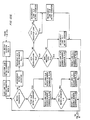
- Figs. 11A and 11 illustrate a flow chart of the program in the redundant remote R 4 (Fig. 1), which serves as a back-up for its assigned primary remotes R 1 , R 2 and R 3 .
- the other redundant remote R B will have the same program except that it will be applied to its assigned remotes R 5 , R 6 , and R 7 .
- a decision instruction sequence 101 to check the status of remote R,. As explained above, it does this by sending a request for information over the communications link CL to remote R 1 asking for the current number in the mailbox of remote R l . It then determines whether this number is greater than zero. If the number is greater than zero, the status of remote R 1 is determined to be operating and the program of the redundant remote R 4 advances to instruction step 103 in which it resets a fail flag for R 1 to 'off' and then enters subroutine 105, in which the current applications program status in remote R 1 is obtained.
- the redundant remote R 4 requests and obtains the current status of the input and output devices in remote R 1 and the current status of the timers and the counters and the flags being used in the applications program of remote R,.
- all of the information that would be needed for the redundant remote R 4 to take over the applications program is obtained from remote R 1 . This information is obtained by sending requests for data and receiving data back over the communications link CL.
- the redundant remote R 4 program proceeds to decision instruction sequence 107, in which the status of remote R 2 is checked in the same manner that was done with respect to R 1 . If the status of remote R 2 is operating, the program advances to instruction step 109, in which the program sets a fail flag for remote R 2 and then proceeds into subroutine 111, in which the status of the applications program for remote- R 2 is obtained in the same manner as for R 1 in subroutine 105. The program then proceeds into a decision instruction sequence 113 to check the status of remote R 3 .
- the program If the status of remote R 3 is operating, then the program resets the fail flag for remote R 3 in instruction step 115 and proceeds into subroutine 117 to obtain the applications program status for remote R 3 in the same manner as for R 1 in subroutine 105. Following subroutine 111, the program returns again to decision instruction sequence 101 to check the status of remote R 1 and the process cyclically repeats.
- decision instruction sequence 101 the program determines that the status R 1 is not operating as indicated by the number in the mailbox of the remote R i , being zero, the program then advances to decision instruction sequence 119, in which the program determines if the fail flag for R 1 is 'on' or 'off'. If the fail flag is 'off', the program proceeds into instruction sequence 121, in which the program attempts to restart the applications program for remote R i . It does this by sending a command over the communications link CL to remote R 1 to direct the communications protocol controller 12 (Fig. 2) to attempt a hardware restart of the applications program. This is carried out by the communications protocol controller 12 pulling a restart wire to ground in the common buss 22.
- this restart wire When this restart wire is pulled to ground, it starts the applications program back through its initialization program and sets all of the flags, timers, and counters just as if power had been turned on. Such a restart is called a hardware restart.
- the redundant remote R 4 could effect a software restart in the failed remote.
- a software restart would merely start the applications program through its initialization program with the timers, counters and flags left in their present status.
- the redundant remote R 4 program After completing instruction sequence 121, the redundant remote R 4 program then sets the fail flag for remote R 1 to 'on' in instruction step 123 and then proceeds into decision instruction sequence 125 to again check the status of remote R 1 by checking the number in the mailbox of remote R 1 in the same manner as in decision instruction sequence 101. If the applications program in remote R 1 was successfully started in instruction sequence 121, the number in the mailbox will not be zero and the program will determine that the status of remote R 1 is operating, whereupon the program will jump to decision instruction sequence 107 to check the status of remote R 2 as already described.
- the program determines that the status of remote R 1 , is not operating in decision instruction sequence 125, then this means that the attempt to restart the applications program in remote R 1 in instruction sequence 121 failed and the redundant remote R 4 program then proceeds into instruction sequence 127 to initialize the input/output management device 14 (also identified in Fig. 11 B as 'RTX') in remote R 1 to receive instructions and data from the redundant remote R 4 instead of from the central processing unit 16 in the remote R 1 and to send data on the status of the input and output devices to the redundant remote R 4 .
- the input/output management device 14 also identified in Fig. 11 B as 'RTX'
- the redundant remote program would proceed directly into the instruction sequence 127 to initialize the input/output management device 14 of remote R 1 to respond to the redundant remote R 4 .
- the purpose of the fail flag which is set to 'on' in instruction step 123 and is reset to 'off' in instruction step 103 is to prevent the redundant remote program from getting hung-up in a condition in which it successfully restarts the remote R 1 only to have the remote R 1 fail again by the time the program of the redundant remote recycles around to checking the mailbox of the remote R, again in decision instruction sequence 101. If this should happen, the fail flag for remote R, will have been set to 'on' in instruction step 123 after the successful restarting of the applications program. Then, the next time that the redundant remote program cycles back to decision instruction sequence 101, and determines that the status of remote R 1 is not operating, the fail flag for remote R 1 will be 'on'.
- the program will jump from decision instruction sequence 119 into the instruction sequence 127 to initialize the remote R 1 to respond to redundant remote R 4 . If the next time the redundant remote program recycles back to decision instruction sequence 101 to check the status of R i , it determines that the status of R 1 is operating, the program will then reset the fail flag to 'off' in instruction step 103 so that in subsequent cycles, should the program determine that the remote R 1 has again failed, the program will again go into the restart instruction sequence 121 instead of immediately jumping to the initialization instruction sequence 127.
- the redundant remote program After the redundant remote program has completed the initialization instruction sequence 127, it then proceeds to subroutine 129. In this subroutine, the status of the applications program of remote R 1 last received by the redundant remote R 4 , which status is stored in the memory of the redundant remote R 4 , is loaded into predetermined registers of the memory of the redundant remote R 4 in order to carry out the applications program of remote R 1 in the redundant remote R 4 . After this subroutine is completed, the program proceeds into instruction sequence 130 and then into the subroutine 131 in which it starts and carries out the applications program.
- the redundant remote R 4 carries out the R 1 applications program by receiving data from remote R 1 as to the status of the input and output devices of the remote R, and sending instructions to remote R, to direct operation of the input/ output management device 14 of the remote R 1 .
- the program in the redundant remote R 4 will then continue to cycle through the applications program for the remote R 1 until it receives a command from the operator to reset it back into its main cycle of checking the status of the remotes R i , R 2 , and R 3 .
- the redundant remote R 4 determines that the status of remote R 2 or remote R 3 is not operating, it then performs the same program with respect to these remotes as described with respect to remote R 1 as is illustrated in Figs. 11A and 11B.
- the redundant remote R B will take over the applications program should any of the primary remotes R 5 -R 7 become nonoperative in the same manner as described above with respect to R 4 serving as a back-up for the primary remotes R 1 -R 3 .
- the provision of the redundant remotes in accordance with the invention decreases malfunctioning of the control system due to one of the primary remotes becoming inoperative as a result of failure of the central processing unit 16 of the primary remote. Because each redundant remote serves as a back-up for several primary remotes, the cost of providing the redundancy is significantly reduced. Because the redundant remotes are themselves each a remote control unit which takes its turn in the master-for-a-moment sequence communicating with the other remotes over the dual channel communications link, the redundant remotes can be provided in the system very inexpensively.
- Each remote R n is provided with termination impedances Z0 and Z1 for the first and second communication channels CH0 and CH1 (Fig. 3) and a line termination relay 32 0 and 32, under the control of the communications link control device 38.
- the termination impedances are connected across each channel of the communications link when the particular remote is the first or the last remote in the system (e.g., R 1 and R 8 in Fig. 1) to establish proper line termination impedance to prevent signal level degradation and the presence of reflected signals, both conditions which can adversely affect the performance of the system.
- the termination impedances Z0 and Z1 are also applied across the appropriate communications channels when a remote determines, as described below, that the communications link CL between it and its immediately adjacent higher or lower number remote is severed or sufficiently degraded that reliable data transmission cannot be maintained therebetween.
- the determination as to communications link degradation can be made by providing each remote with a register for each communications channel that records, in a cumulative manner, the number of invalid messages received from the immediately adjacent remote(s) and terminate one or both of the communications link CL0 and CL1 in the direction of the remote from which the number of invalid messages received exceeds a threshold value.
- each remote is provided with an active testing diagnostic routine to enable it to test the communication integrity of the communications link between it and its immediately adjacent remote(s) in accordance with the flow diagrams illustrated in Figs. 12, 12A, 13B and 12C as read in accordance with Fig. 13 and the table of Fig. 14.
- the flow diagram illustrated in Fig. 12 is a summary of the manner by which each remote is capable of testing the communication integrity of the communications link CL between it and its immediate adjacent remote or remotes and terminating one or both of the communications links, CL0 and CL1, when a degraded or interrupted line condition is detected.
- the remote R x is initialized and then, in sequence, tests the communications integrity of the communications link CL0 in the downstream direction between it and its immediately adjacent lower number remote (that is, R x-1 ) and then tests the communication integrity of the communications link CL1 in the downstream direction with the same remote. If either the communications link CL0 or CL1 in the downstream direction is faulty, an appropriate flag is set in a register in the remote R x reserved for this purpose.
- the remote R x then tests the communications integrity of the communications link CL0 and CL1 in the upstream direction with its immediately adjacent higher number remote (that is, remote R x-1 ) and sets the appropriate flag, as and if required. After this initial diagnostic checking takes place, the remote R x will terminate the failed communications line CL0 and/or CL1 by actuating the appropriate relay contacts 32 0 and/or 32 1 as required.
- the line checking test utilized in Fig. 12 preferably takes place when the remote R x is master-for-the-moment (that is, R m ).
- FIG. 12A represents the downstream integrity check with the next lower number remote
- Fig. 12B represents the upstream integrity check with the next higher number remote
- Fig. 12C represents the line termination function in response to the results of the integrity test performed in Figs. 12A and 12B.
- the line checking diagnostic is started by first loading three registers or counters, namely, a 'retry counter', a 'CL0 retry counter', and a 'CL1 retry counter' with an arbitrarily selected number, for example, five.
- the 'retry counter' is then decremented by one and a message sent from the remote R x to the remote R x -, requesting an acknowledgement ACK signal. If the communications link CL0 and CL1 between the interrogating remote and the responding remote is fully functional, a valid ACK signal will be received by the interrogating remote R x on both CL0 and CL1.
- the diagnostic checking will then route to the part of the program (Fig.
- the flow diagram of Fig. 12B is basically the same as that of Fig. 12A except that the communications integrity check occurs for that portion of the communications link CL between the interrogating remote R x and the next higher number responding remote R x-1 . More specifically, the three registers or counters, that is, the 'retry counter', the 'CL0 retry counter', and the 'CL1 retry counter' are loaded with the arbitrarily selected value of five. The 'retry counter' is then decremented by one and a message sent from the interrogating remote R x to the remote R x-1 requesting an acknowledgement signal.
- the appropriate retry counter that is, the "CL0 or CL1 retry counter' will be decremented by one and the procedure repeated until the 'retry counter' is zero at which point the appropriate CL0 and/or CL1 termination flag register will be set; thereafter, the program diagnostic will route to the line impedance termination portion shown in Fig. 12C.
- a line termination relay can also be released (that is, reset) to remove a previously applied line termination impedance. Accordingly, the system provides each remote with the ability to remove a line termination as well as apply a line termination. This particular feature is desirable when a communication link is temporarily degraded by the presence of non-recurring electrical noise to permit the system to automatically reconfigure its line impedances.
- the 'retry counter' is decremented by one and the requesting interrogating remote R 4 (R x ) requests an acknowledgement from the responding remote R 3 (that is, R x-1 ).
- the requested acknowledgement will be provided on line CL1 but not line CL0 because of the aforementioned interruption at point A (Fig. 1).
- the interrogating remote R 4 not receiving the requested acknowledgement signal on communications link CLO, will decrement the 'CLO retry counter' by one. Thereafter, the retest procedure will be sequentially continued with the 'CL0 retry counter' being decremented with each additional unsuccessful attempt to obtain an acknowledgement from remote R 3 through the communications link CLO.
- the remote R 4 will thereafter continue the diagnostic checking procedure to test the communications integrity of that portion of the communications link between the remote R 4 (R x ) and the next adjacent higher remote R s (that is, R x-1 ) in accordance with the flow diagram of Fig. 12B.
- the termination relay contacts 32 0 (Fig. 3) will be set to terminate the communications link CL0 at the remote R 4 .
- the remote R 3 when it becomes master-for-the-moment, will also apply a termination impedance across the communications link CLO.
- the remotes R o ... R n have the ability, even when one or both of the communication links CL0 and CL1 are severed to still function on a master-for-the-moment basis and also to effect appropriate line termination to minimize the adverse effect on digital data signal strength and the generation of reflected signals from mismatched line impedance caused by deteriorated or severed communication lines.
- the system is self-healing, that is, when reliable communications is restored over the severed or degraded portion of the communications link the remotes R " will then again function to remove the line impedances to resume full system operation.
Landscapes
- Engineering & Computer Science (AREA)
- Computer Networks & Wireless Communication (AREA)
- Signal Processing (AREA)
- Theoretical Computer Science (AREA)
- Physics & Mathematics (AREA)
- General Engineering & Computer Science (AREA)
- General Physics & Mathematics (AREA)
- Quality & Reliability (AREA)
- Computer Hardware Design (AREA)
- Automation & Control Theory (AREA)
- Electromagnetism (AREA)
- Selective Calling Equipment (AREA)
Claims (4)
Applications Claiming Priority (10)
| Application Number | Priority Date | Filing Date | Title |
|---|---|---|---|
| US06/115,161 US4304001A (en) | 1980-01-24 | 1980-01-24 | Industrial control system with interconnected remotely located computer control units |
| US115160 | 1980-01-24 | ||
| US06/115,160 US4352103A (en) | 1980-01-24 | 1980-01-24 | Industrial control system |
| US115161 | 1980-01-24 | ||
| US159597 | 1980-06-16 | ||
| US06/159,597 US4347563A (en) | 1980-06-16 | 1980-06-16 | Industrial control system |
| US20247280A | 1980-10-31 | 1980-10-31 | |
| US202471 | 1980-10-31 | ||
| US202472 | 1980-10-31 | ||
| US06/202,471 US4402082A (en) | 1980-10-31 | 1980-10-31 | Automatic line termination in distributed industrial process control system |
Publications (3)
| Publication Number | Publication Date |
|---|---|
| EP0033228A2 EP0033228A2 (fr) | 1981-08-05 |
| EP0033228A3 EP0033228A3 (en) | 1982-10-13 |
| EP0033228B1 true EP0033228B1 (fr) | 1986-09-17 |
Family
ID=27537402
Family Applications (1)
| Application Number | Title | Priority Date | Filing Date |
|---|---|---|---|
| EP81300292A Expired EP0033228B1 (fr) | 1980-01-24 | 1981-01-22 | Système de commande industriel |
Country Status (5)
| Country | Link |
|---|---|
| EP (1) | EP0033228B1 (fr) |
| AU (1) | AU537919B2 (fr) |
| CA (1) | CA1171543A (fr) |
| DE (1) | DE3175318D1 (fr) |
| MX (1) | MX151348A (fr) |
Families Citing this family (19)
| Publication number | Priority date | Publication date | Assignee | Title |
|---|---|---|---|---|
| US4491946A (en) * | 1981-03-09 | 1985-01-01 | Gould Inc. | Multi-station token pass communication system |
| WO1983002206A1 (fr) * | 1981-12-17 | 1983-06-23 | Davis, Barrie, William | Systeme de communications a commande distribuee |
| US4627045A (en) * | 1984-02-14 | 1986-12-02 | Rosemount Inc. | Alternating communication channel switchover system |
| FR2565050B1 (fr) * | 1984-05-22 | 1990-03-09 | Merlin Gerin | Procede et systeme de transmission de messages entre plusieurs stations d'un reseau local industriel decentralise a protocole d'acces deterministe par circulation de jeton |
| US5012468A (en) * | 1989-12-28 | 1991-04-30 | Allen-Bradley Company, Inc. | Master slave industrial token passing network |
| JP3268456B2 (ja) * | 1992-09-04 | 2002-03-25 | フォールト トレラント システムズ エフテーエス−コンピュータ テクニク ゲセムベーハー | 通信制御装置及び情報伝達方法 |
| GB2272611A (en) * | 1992-11-05 | 1994-05-18 | Integrated Control Platforms L | Control system for machinery and/or plant apparatus |
| EP0698837B1 (fr) * | 1994-08-12 | 1997-04-23 | Siemens Aktiengesellschaft | Procédé et appareil de transfert de données périodique avec fonction de diffusion pour un échange indépendant de données entre unités périphériques externes |
| CN1171872A (zh) * | 1994-11-11 | 1998-01-28 | 西门子公司 | 由下一级控制设备向上一级控制设备发送信号的方法 |
| JPH10307777A (ja) * | 1997-05-06 | 1998-11-17 | Yazaki Corp | 状態情報の管理方法及びそのシステム |
| US6138049A (en) * | 1997-08-22 | 2000-10-24 | Honeywell International Inc. | System and methods for generating and distributing alarm and event notifications |
| DE10136758B4 (de) * | 2001-07-27 | 2010-10-21 | Siemens Ag | Verfahren zur Datenübertragung |
| JP2003333675A (ja) * | 2002-05-14 | 2003-11-21 | Hitachi Ltd | 通信系制御装置およびそれの異常監視方法 |
| US8676357B2 (en) | 2005-12-20 | 2014-03-18 | Fieldbus Foundation | System and method for implementing an extended safety instrumented system |
| EP1974278A4 (fr) * | 2005-12-20 | 2012-01-04 | Fieldbus Foundation | Systeme et procede pour mettre en oeuvre des systemes instrumentes de securite |
| US7953501B2 (en) * | 2006-09-25 | 2011-05-31 | Fisher-Rosemount Systems, Inc. | Industrial process control loop monitor |
| DE102006054124B4 (de) * | 2006-11-15 | 2009-05-28 | Phoenix Contact Gmbh & Co. Kg | Verfahren und System zur sicheren Datenübertragung |
| JP6480477B2 (ja) | 2014-06-26 | 2019-03-13 | スリーエム イノベイティブ プロパティズ カンパニー | メルトブローンブレンドポリマー繊維を含む熱安定性不織布ウェブ |
| DE102014221788A1 (de) * | 2014-10-27 | 2016-04-28 | Zumtobel Lighting Gmbh | Gebäudetechnik-Bussystem zum Betrieb von Gebäudetechnik-Geräten |
Family Cites Families (11)
| Publication number | Priority date | Publication date | Assignee | Title |
|---|---|---|---|---|
| BE559555A (fr) * | 1956-07-27 | |||
| FR1303478A (fr) * | 1961-06-07 | 1962-09-14 | Constr Telephoniques | Système d'affichage et d'enregistrement de signalisations |
| GB1009349A (en) * | 1964-09-16 | 1965-11-10 | Standard Telephones Cables Ltd | Telecommunication signalling |
| GB1115865A (en) * | 1965-01-29 | 1968-05-29 | Standard Telephones Cables Ltd | Signalling system |
| DE1293817B (de) * | 1967-11-10 | 1969-04-30 | Telefunken Patent | Verfahren zur gesicherten UEbertragung binaer kodierter Informationen |
| US3624603A (en) * | 1969-09-16 | 1971-11-30 | Gen Electric | Digital data communications system with means for improving system security |
| DE1958727A1 (de) * | 1969-11-22 | 1971-05-27 | Licentia Gmbh | Verfahren zur gesicherten UEbertragung von Daten,insbesondere Peilinformationen |
| JPS5434501B2 (fr) * | 1974-02-15 | 1979-10-27 | ||
| JPS5215204A (en) * | 1975-07-26 | 1977-02-04 | Fuji Electric Co Ltd | Informatioon transmission system |
| DE2808937B2 (de) * | 1978-03-02 | 1981-06-04 | Standard Elektrik Lorenz Ag, 7000 Stuttgart | Fernwirksystem |
| DE3012438A1 (de) * | 1979-04-06 | 1980-10-16 | Fuji Electric Co Ltd | Daten-uebertragungs-system |
-
1981
- 1981-01-19 CA CA000368795A patent/CA1171543A/fr not_active Expired
- 1981-01-22 EP EP81300292A patent/EP0033228B1/fr not_active Expired
- 1981-01-22 DE DE8181300292T patent/DE3175318D1/de not_active Expired
- 1981-01-22 MX MX185651A patent/MX151348A/es unknown
- 1981-01-23 AU AU66569/81A patent/AU537919B2/en not_active Ceased
Also Published As
| Publication number | Publication date |
|---|---|
| AU6656981A (en) | 1981-07-30 |
| EP0033228A3 (en) | 1982-10-13 |
| CA1171543A (fr) | 1984-07-24 |
| AU537919B2 (en) | 1984-07-19 |
| MX151348A (es) | 1984-11-12 |
| DE3175318D1 (en) | 1986-10-23 |
| EP0033228A2 (fr) | 1981-08-05 |
Similar Documents
| Publication | Publication Date | Title |
|---|---|---|
| US4347563A (en) | Industrial control system | |
| US4410983A (en) | Distributed industrial control system with remote stations taking turns supervising communications link between the remote stations | |
| EP0033228B1 (fr) | Système de commande industriel | |
| US4352103A (en) | Industrial control system | |
| US4402082A (en) | Automatic line termination in distributed industrial process control system | |
| US5084871A (en) | Flow control of messages in a local area network | |
| US4845722A (en) | Computer interconnect coupler employing crossbar switching | |
| US4897833A (en) | Hierarchical arbitration system | |
| US4354267A (en) | Data transmission system utilizing loop transmission lines between terminal units | |
| US5301186A (en) | High speed transmission line interface | |
| CA1244155A (fr) | Protocole de communication pour systeme de controle de bus reparti | |
| CN105871623B (zh) | 一种现场总线的偶发性故障诊断方法 | |
| JPS6079844A (ja) | ホツトキヤリア発生場所監視方法 | |
| EP0435037B1 (fr) | Réseau industriel à passage de jeton du type maître-esclave | |
| US4583089A (en) | Distributed computer control system with variable monitor timers | |
| US4509117A (en) | Communications network access rights arbitration | |
| US5021777A (en) | Mode-selectable communications system | |
| EP1999908B1 (fr) | Appareil de detection d'erreurs dans un systeme de communication | |
| CA1182567A (fr) | Terminaison automatique des lignes d'un systeme de controle de procede industriel | |
| CA1182572A (fr) | Systeme de controle industriel | |
| CA1182568A (fr) | Systeme de controle industriel | |
| JP2644571B2 (ja) | 遠隔ipl制御方式 | |
| JPH0612290A (ja) | 制御データ監視方式 | |
| JPS61152142A (ja) | デ−タ受渡方式 | |
| JPH05153144A (ja) | ネツトワークにおける回線劣化診断方式 |
Legal Events
| Date | Code | Title | Description |
|---|---|---|---|
| PUAI | Public reference made under article 153(3) epc to a published international application that has entered the european phase |
Free format text: ORIGINAL CODE: 0009012 |
|
| AK | Designated contracting states |
Designated state(s): CH DE FR GB IT NL |
|
| PUAL | Search report despatched |
Free format text: ORIGINAL CODE: 0009013 |
|
| AK | Designated contracting states |
Designated state(s): CH DE FR GB IT NL |
|
| 17P | Request for examination filed |
Effective date: 19830309 |
|
| GRAA | (expected) grant |
Free format text: ORIGINAL CODE: 0009210 |
|
| AK | Designated contracting states |
Kind code of ref document: B1 Designated state(s): CH DE FR GB IT LI NL |
|
| ITF | It: translation for a ep patent filed | ||
| REF | Corresponds to: |
Ref document number: 3175318 Country of ref document: DE Date of ref document: 19861023 |
|
| ET | Fr: translation filed | ||
| PLBE | No opposition filed within time limit |
Free format text: ORIGINAL CODE: 0009261 |
|
| STAA | Information on the status of an ep patent application or granted ep patent |
Free format text: STATUS: NO OPPOSITION FILED WITHIN TIME LIMIT |
|
| 26N | No opposition filed | ||
| PGFP | Annual fee paid to national office [announced via postgrant information from national office to epo] |
Ref country code: FR Payment date: 19890112 Year of fee payment: 9 |
|
| PGFP | Annual fee paid to national office [announced via postgrant information from national office to epo] |
Ref country code: CH Payment date: 19890126 Year of fee payment: 9 |
|
| ITTA | It: last paid annual fee | ||
| PGFP | Annual fee paid to national office [announced via postgrant information from national office to epo] |
Ref country code: NL Payment date: 19890131 Year of fee payment: 13 Ref country code: GB Payment date: 19890131 Year of fee payment: 9 |
|
| PGFP | Annual fee paid to national office [announced via postgrant information from national office to epo] |
Ref country code: DE Payment date: 19890228 Year of fee payment: 9 |
|
| PG25 | Lapsed in a contracting state [announced via postgrant information from national office to epo] |
Ref country code: GB Effective date: 19900122 |
|
| PG25 | Lapsed in a contracting state [announced via postgrant information from national office to epo] |
Ref country code: LI Effective date: 19900131 Ref country code: CH Effective date: 19900131 |
|
| PG25 | Lapsed in a contracting state [announced via postgrant information from national office to epo] |
Ref country code: NL Effective date: 19900801 |
|
| NLV4 | Nl: lapsed or anulled due to non-payment of the annual fee | ||
| GBPC | Gb: european patent ceased through non-payment of renewal fee | ||
| PG25 | Lapsed in a contracting state [announced via postgrant information from national office to epo] |
Ref country code: FR Effective date: 19900928 |
|
| REG | Reference to a national code |
Ref country code: CH Ref legal event code: PL |
|
| PG25 | Lapsed in a contracting state [announced via postgrant information from national office to epo] |
Ref country code: DE Effective date: 19901002 |
|
| REG | Reference to a national code |
Ref country code: FR Ref legal event code: ST |