EP0033475A1 - Escabeau - Google Patents
Escabeau Download PDFInfo
- Publication number
- EP0033475A1 EP0033475A1 EP81100404A EP81100404A EP0033475A1 EP 0033475 A1 EP0033475 A1 EP 0033475A1 EP 81100404 A EP81100404 A EP 81100404A EP 81100404 A EP81100404 A EP 81100404A EP 0033475 A1 EP0033475 A1 EP 0033475A1
- Authority
- EP
- European Patent Office
- Prior art keywords
- spars
- legs
- leg
- ladder
- steps
- Prior art date
- Legal status (The legal status is an assumption and is not a legal conclusion. Google has not performed a legal analysis and makes no representation as to the accuracy of the status listed.)
- Granted
Links
- 238000005452 bending Methods 0.000 claims abstract description 5
- 239000004020 conductor Substances 0.000 claims description 5
- 125000006850 spacer group Chemical group 0.000 claims description 4
- 210000001364 upper extremity Anatomy 0.000 description 8
- 238000010276 construction Methods 0.000 description 5
- 229910052782 aluminium Inorganic materials 0.000 description 2
- XAGFODPZIPBFFR-UHFFFAOYSA-N aluminium Chemical compound [Al] XAGFODPZIPBFFR-UHFFFAOYSA-N 0.000 description 2
- 230000037396 body weight Effects 0.000 description 2
- 206010017577 Gait disturbance Diseases 0.000 description 1
- 230000003247 decreasing effect Effects 0.000 description 1
- 229910052751 metal Inorganic materials 0.000 description 1
- 239000002184 metal Substances 0.000 description 1
- 230000004048 modification Effects 0.000 description 1
- 238000012986 modification Methods 0.000 description 1
- 230000000284 resting effect Effects 0.000 description 1
- 239000013589 supplement Substances 0.000 description 1
Images


Classifications
-
- E—FIXED CONSTRUCTIONS
- E06—DOORS, WINDOWS, SHUTTERS, OR ROLLER BLINDS IN GENERAL; LADDERS
- E06C—LADDERS
- E06C1/00—Ladders in general
- E06C1/02—Ladders in general with rigid longitudinal member or members
- E06C1/38—Special constructions of ladders, e.g. ladders with more or less than two longitudinal members, ladders with movable rungs or other treads, longitudinally-foldable ladders
- E06C1/39—Ladders having platforms; Ladders changeable into platforms
- E06C1/393—Ladders having platforms foldable with the ladder
-
- E—FIXED CONSTRUCTIONS
- E06—DOORS, WINDOWS, SHUTTERS, OR ROLLER BLINDS IN GENERAL; LADDERS
- E06C—LADDERS
- E06C1/00—Ladders in general
- E06C1/02—Ladders in general with rigid longitudinal member or members
- E06C1/14—Ladders capable of standing by themselves
- E06C1/16—Ladders capable of standing by themselves with hinged struts which rest on the ground
- E06C1/20—Ladders capable of standing by themselves with hinged struts which rest on the ground with supporting struts formed as poles
-
- E—FIXED CONSTRUCTIONS
- E06—DOORS, WINDOWS, SHUTTERS, OR ROLLER BLINDS IN GENERAL; LADDERS
- E06C—LADDERS
- E06C1/00—Ladders in general
- E06C1/02—Ladders in general with rigid longitudinal member or members
- E06C1/38—Special constructions of ladders, e.g. ladders with more or less than two longitudinal members, ladders with movable rungs or other treads, longitudinally-foldable ladders
- E06C1/387—Special constructions of ladders, e.g. ladders with more or less than two longitudinal members, ladders with movable rungs or other treads, longitudinally-foldable ladders having tip-up steps
Definitions
- the invention relates to a step ladder, of the two legs of which are connected to one another in the region of their upper end so as to be pivotable about an axis Footprint of the ladder are formed in horizontal planes, plate-shaped steps, which are pivotally connected about mutually parallel axes to the bars and to these parallel handlebars.
- the invention has for its object to provide a stepladder, the upward and downward having to look just as comfortable and safe, without a stop both, be - is walkable as a common, fixed stairs, but which nevertheless has a simple, low-weight construction and has a minimal space requirement when folded.
- this object is achieved according to the invention in that the bars and the handlebars have a mutual support which increases the bending stiffness and the pivotability of the treads about their axis in a pivoting support at maximum spreading of the legs, that the treads have a torque on walking in the sense of an approach of the handlebars to the spars overhang on the side facing away from the other leg of the spars and that the depth of the steps and the height differences between two successive steps are in the usual range for stairs.
- the handlebars By supporting the bars and handlebars against each other with maximum spreading of the legs, the handlebars increase the bending stiffness of the bars, which increases the load-bearing capacity and stability of the ladder.
- the spars can therefore be made weaker and therefore lighter in weight and more space-saving than if there were no mutual support.
- the force with which the bars and handlebars are pressed against one another is increased by the body weight of the user resting on one or two steps, which ensures fully effective support. This also ensures that the maximum spread of the legs desired for reasons of stability is inevitably achieved.
- the protrusion of the steps over the front of the spars has, in addition to the generation of a torque which affects the spreading and the support, also the advantage that the lower ends of the spar do not interfere and do not form trip hazards, which is important for the safety of the user of the ladder is.
- the depth of the steps which is adapted to the dimensions of conventional stairs, and the difference in height between two successive steps ensures that the step ladder can be walked on as comfortably and safely as a fixed staircase.
- a mutual support of bars and handlebars can be achieved with an arrangement of the handlebars in front of the front side of the bars facing away from the other leg.
- the mutual support between the spars and handlebars can be achieved in that the arms rest on the spars at maximum spreading of the legs.
- the handlebars can also be supported on the spars via spacers. The latter possibility is particularly advantageous when a risk of crushing the fingers of the user when spreading the two legs of the ladder must be excluded.
- the handlebars end at a distance from the lower end of the spars and only extend to the lowest step.
- the bars and handlebars do not impair the usability of the uppermost step as a step surface and as a storage area, it is / is usually expedient if the bars and the handlebars extend at most to the level defined by the step surface of the uppermost step with maximum spread of the legs . However, it may also be desirable if the bars of one of the two legs have an extension beyond the uppermost step, for example to form a handle for the user or to carry a storage plate or the like.
- the handlebars can each be connected to one of the two spars of the other leg via a slot-pin guide.
- This is a very simple and space-saving construction.
- you can also connect the two legs of the ladder to each other by at least one pivot lever.
- Such a pivot lever makes it possible to positively set the maximum spread angle of the conductor legs even without a locking device and to prevent the two conductor legs from collapsing unintentionally Secure ladder.
- the pivot lever can either engage in a slot guide of the other leg by means of a driver or can be articulated at a fixed location on the other leg. In the latter case, however, an articulated division of one arm of the pivot lever or the use of an intermediate lever is required.
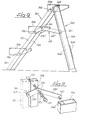
- the first embodiment according to FIGS. 1 to 5 is a fixed ladder with two legs 201 and 202 each made of two parallel bars 203 and 204, respectively.
- One leg 201 is provided with three steps 206 and two parallel links 211.
- the other leg 202 has no steps and is provided with a stiffening plate 216 instead of a cross member, which rigidly connects the two bars 204 together.
- the identical treads 206 extend horizontally from spar 203 to spar 203 and are rotatably mounted at points 218 of spars 203 about a horizontal axis lying in the central plane M of their tread width a.
- the treads 206 which are placed horizontally, in FIG Intermediate protruding rear edges 224 of the treads are rotatably mounted about horizontal parallel axes at the locations 226 of the two links 211, so that each tread while rotating about its two bearings are 218 pivotable about their two bearing points 226, which can move in circular arcs around the bearing points 218.
- each link 211 rests on the spar 203 associated with it, the handlebar-fixed but moving bearing points 226 being higher than the spar-fixed bearing points 218.
- the bars By placing the handlebars 211 on the bars 203 in the position with maximum spread, the bars increase the bending stiffness of the bars 203, which increases the load-bearing capacity and stability of the ladder.
- the bars can therefore be made weaker and thus less weight and space-saving than if there were no mutual support between the bars 203 and the links 211.
- the system pressure is increased by the body weight on one or two steps, which ensures good support. This also ensures that the maximum spread required for reasons of stability is inevitably achieved.
- the protrusion of the steps over the front of the spars also has the advantage that the lower spar ends no longer interfere. no appearance and / stumbling thresholds, which is also important for the safety of the user of the ladder.
- the height difference between two successive steps 206, the depth or tread width a and the inclination of the bars 203 with maximum spreading of the legs 201 and 202 are selected so that the ladder is as easy and safe to walk as a fixed staircase, especially since the steps 206 overlap very little, as Fig. 2 shows.
- the preferred one for fixed stairs The slope, which is equal to the quotient of the height difference and the tread width, is between about 0.44 and 0.77.
- each spar 204 of the rear leg 202 is a hollow profile rod with a groove 228 open to the other rear spar 204, a slot-pin guide with a hollow pin 230 which projects laterally outwards from the associated link 211 and engages in the continuous groove 228, which extends parallel to the rear spar 204.
- the two links 211 lie between the two rear spars 204, the lateral spacing of which is greater than the lateral spacing of the front spars 203, the lower ends of which each carry a shoe 232 which has two footprints 234 and 236 including an obtuse outer angle oC which the longer one leg 201 with the maximum spread of both legs or the entire ladder with closed legs 201 and 202 stands on the floor 238.
- a hoof-like shoe 240 is sufficient on the shorter rear spars 204.
- each groove 228 has in its base an overhead bore 242 and a deep bore 244, in which a locking bolt 246 optionally engages is longitudinally displaceably mounted in one of the hollow pins 230 and is under spring pressure and can be withdrawn from the occupied bore for unlocking with the aid of a pull cable 248 common to both bolts.
- the relative dimensions of the ladder parts are chosen so that when the legs 201 and 202 of the folded fixed ladder are spread out, the links 211 guided on the rear leg 202 pivot the treads 206 until they are level be right when the handlebars strike the front bars 203 and the legs are maximally spread, and that conversely when the maximally spread legs are folded, the handlebars 211 are returned and the steps 206 are turned back.
- the handlebars 211 lie against the front bars 203 even when the ladder is folded, the treads 222 lying in one plane. In this position, the ladder has a minimal space requirement.
- the step shown in FIG. 6 is a modification of the steps 206.
- This modified embodiment which can be provided for the ladder according to FIGS. 1 to 5 instead of the steps 206, consists, as shown, of two or more same tread parts 250, which are attached to two horizontal and parallel, round rung bars 252 and 254 so that they do not form any gaps.
- the lower rung bars 252 are mounted on the front spars, where the locations 218 are in the first embodiment. Accordingly, the higher rung bars 254 are mounted on the handlebars where the locations 226 are in the first embodiment.
- tread parts 250 of the same tread are covered with a continuous rubber mat 256.
- FIG. 7 and 8 show a supplement to the first exemplary embodiment by a tray bracket 258.
- the tray bracket 258 consists essentially of two straight, parallel cantilever arms 260 and of a flat, rectangular, flat, that is plate-shaped tray 262, the front edge 264 of which is rolled up and receives a pivot axis 266, the two ends of which are each supported on a cantilever arm 260.
- the two extension arms 260 each have one protruding at a right angle Tab 268 flanking the front tablet edge 264 at both ends. Outside of its front edge 264, the tray 262 extends in the direction parallel to the edge beyond both edge ends, in each case by a piece that corresponds at least to the thickness of the tabs 268.
- the protrusion serves as a stop for the tray 262 on the extension arm 260.
- the two extension arms 260 are articulated at a maximum distance from one another on the upper ends of the rear leg columns 204, so that they can be pivoted together about a horizontal axis.
- the tray bracket 258 can be locked in that the hinged ends of the two extension arms 260, which do not support the tray 262, thanks to their fork-shaped design and two rotary and push joints 272 the common axis 27 0 can be brought into engagement with a locking bolt 274, which is attached to the upper end of each rear spar 203 projecting laterally outwards.
- its tray 262 is between a horizontal provision, which is shown in FIG.
- the other end position of the tray bracket 258 assumed before and after use with downward orientation, which is achieved after the tray bracket has been pivoted downward, is determined by the contact of the edge 264 of the tray 262 in its lowered position on the two rear bars 203.
- the tray 262 In both end positions Towards the tray bracket 258, the tray 262 cannot leave its retracted position on its own, since it is held in this position by its own weight in contact with the two extension arms 260.
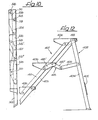
- the two legs 301 and 302 of the second exemplary embodiment of a fixed ladder shown in FIGS. 9 to 11 each have two bars 303 and 304 and are pivotally connected to one another in the region of the upper end of the bars.
- the bars 304 are connected to one another at a distance from their lower end which forms the standing surface by a plate-shaped cross member 305, so that the leg 302 has sufficient stability.
- steps 306 are arranged at equal intervals in the longitudinal direction of the leg, which, as shown in FIG. 9, extend from one spar of the leg 301 to the other.
- the treads 306, which are all of the same design, are made of sheet metal, for reasons of weight, of an aluminum sheet.
- the sheet is folded down on all four sides of the rectangular tread, which not only ensures high rigidity and stability of the steps even when using a relatively thin sheet, but also has a bearing cheek on each side.
- the uppermost step is mounted approximately in the middle between its front and rear edge on the axis 318 connecting the two legs.
- this axis is formed by a continuous rod.
- two bearing journals aligned with one another could also be provided.
- the two remaining steps 306, like the uppermost step, are pivotally mounted in the leg 301.
- len are offset to different degrees relative to the bearing point of the uppermost step towards the rear step edge, so that the slope of the stairs formed by steps 306 is less than the slope of the leg 301 with the maximum spread of both legs.
- This maximum spreading angle and the height difference between two successive steps and the step depth are chosen so that in the use position there is a position of the steps as is usual with stairs.
- the protrusion of the step 306 forward over the spars 303 from top to bottom, it is also achieved that the lower end of these spars does not protrude or does not protrude significantly beyond the lowest step. Furthermore, the smaller overhang of the top step compared to the other steps reduces the length of the ladder in the folded state.
- the bearing points 316 are selected in the region of the bearing cheeks so that each link 311 rests against the front of the spar 303 with which the legs 301, 302 are maximally spread, while keeping the tread of the steps 306 in a horizontal position when the ladder is on a horizontal surface.
- the bearing capacity and stability of the leg 301 is increased by this arrangement of the links 311 on the bars 303.
- the bars 303 and the handlebar 311 can therefore be relatively thin-walled aluminum be minimum profiles. This also applies to the bars 304, the width of which is selected such that, as shown in FIG. 10, when the ladder is folded, the bars 303 and the handlebars 311 also in contact with them in this position and the steps 306 do not protrude forwards or backwards .
- the handlebars 311 only need to extend from the top to the bottom step 306. However, for aesthetic reasons, they can also be led to the lower end of the spars 303, which is indicated in FIG. 9 by dashed lines. However, it must be ensured that the spars 303 and not the handlebars 311 form the base.
- a pivot lever 315 is provided on each side of the ladder.
- pivot levers 315 serve to positively limit the spreadability of the two legs 301 and 302 to the maximum spread angle.
- the pivot levers 311 are double-armed levers, the two arms 315 'and 315 "of different lengths enclosing an obtuse angle which is open downwards in the use position of the ladder.
- the leg 301 lies between one and the other other shorter rm a 315 ', and the two longer arms 315 "engage between the spars 304 of the leg 302nd So that no additional articulation points are required for a pivotable connection of the shorter arm 315 'to the spar 303 and the handlebar 311, in the exemplary embodiment the two pivot levers 315 are mounted on the pivot axis connecting the middle step 306 with the spars 303, and for the articulation of the The free end of its shorter arm 315 'on the handlebar is provided with the pin 317 connecting it to the step.
- This pin 317 is like Fig. 11 shows, firmly connected to the handlebar 315 at one end. When installed, it passes through holes in the handlebars and the bearing cheek of the middle step, which are aligned.
- the frictional torque is between the two pivot levers 315 and the bars 303 adjustable.
- the pivot axis of the middle step 306 is designed as a continuous rod 319, which is firmly connected at both ends to the bars 303 and each has a central blind hole with an internal thread.
- a screw 321 forming the bearing pin for the swivel lever 315 is screwed into this internal thread, on which, as shown in FIG.
- a spring ring 323 abutting the screw head and two washers 325 are arranged, which abut one or the other side of the swivel lever 315 .
- a roller 327 is cantilevered, which projects outward from the pivot lever and engages in an inwardly open guide groove 304 'of the hollow profile rod, from which the bars 304 of the leg 302 are made Unfolding and collapsing the conductors, the rollers 327 move in the guide grooves 304 'which extend in the longitudinal direction of the bars 304.
- it is not necessary to limit the displaceability of the rollers in the longitudinal direction of the groove for the purpose of limiting the spreading angle of the legs because the two pivot levers cannot carry out any further pivotal movement relative to the spars 303 when the links 311 abut against them.
- the spreading angle of the legs cannot therefore exceed the size shown in FIG. 9 can be enlarged because this would require a further pivoting movement of the pivot lever 315 counterclockwise around the axis defined by the screw 321.
- the third exemplary embodiment shown in FIG. 12 corresponds, as a comparison with FIG. 9 shows, in essential features to the second exemplary embodiment.
- Corresponding parts are therefore identified with reference numerals 100 times larger, and the following explanation is limited to the different features. With regard to the other features, reference is made to the explanations relating to the second exemplary embodiment.
- the steps 406 of the same design are all connected to the bars 404 of the leg 401 and the handlebars 411 in such a way that they have the same projection over the handlebars 411 in the use position of the ladder.
- they could also have the staggered arrangement shown in FIG. 9, just as, on the other hand, the steps 306 of the second exemplary embodiment could all have an equally large projection over the handlebars 311.
- a rod-shaped or tubular axis extending from one spar to the other is provided, of which the one carrying the uppermost step also forms the articulated axis 418 of the fixed ladder, to connect the steps 406 with the two links 411 and the latter with one of the two pivot levers 415 with the help of a rivet.
- each of the two pivot levers 415 us Equipments- as in the second A, for example as a double Levers are formed, the both arms 415 'and 415 "form an obtuse angle which is open at the bottom and is articulated at the end of the end pointing towards the leg 402 to the one end of an intermediate lever 426, the other end of which is articulated on the inside of the adjacent bar 404.
- This articulation point is selected so that the arm 415 "and the intermediate lever 426 form an obtuse, upwardly open angle when the two legs 401 and 402 are spread to the maximum angle.
- the pivot levers 415 are pivoted clockwise in a viewing direction according to FIG. 12, as is also the case with the pivot levers 315 of the first exemplary embodiment.
- FIG. 13 shows a fourth exemplary embodiment of the fixed ladder according to the invention.
- This exemplary embodiment differs from the exemplary embodiments already described in that the spars 504 forming the rear leg 502 are extended beyond the connection point with the spars 503 of the front leg 501. These extensions form a handle that the user can hold onto the ladder. The upper end of the extensions is therefore connected by a cross bar.
- a tray could also be attached to the extensions, as shown in the exemplary embodiment according to FIGS. 7 and 8.
- the construction is chosen so that the legs of the ladder can be spread or folded without the risk of the user's fingers can be clamped between two parts moving relative to one another, in particular between the spars of the rear or front leg or between the spars of the front leg and the handlebars.
- spacers 530 are therefore provided which, as shown in FIG. 13, show the links 511 with the legs spreading to the maximum keep a sufficient distance from the bars 503.
- the front leg Due to the support via the spacer body 530, in which it is plastic parts, which are partially inserted into the upper and lower end of the link and thereby connected thereto, the front leg also receives 501 the B ockleiter in the position of use to increase the stiffness and stability through the 511 handlebars.
- the two pivot levers 515 are identically constructed two-armed lever, he WEL c are pivotally mounted on one of the axes 521, which connect the treads 506 is pivotally connected to the spars 503rd
- One arm of the pivot lever 51 5 extends from this bearing point to the articulation point, which connects the step 511 associated with the link to the handlebar 511.
- the other arm is divided into two articulated sections so that it does not require a slot-and-pin guide, and its distal end is on Handlebar 504 of rear leg 502 articulated. However, it would of course also be possible to form this arm rigidly and to provide a pin at its distal end which engages in a guide groove of the spar 504.
- each of the two spars 503 of the front leg 501 is articulated to a connecting strap 531 which is fastened to the associated spar 504 of the rear leg and extends as far from it extends at the front, that when the two legs are parallel, there is a distance between the spars 503 and 504 that excludes the risk of crushing.
- This distance is maintained in the region of the lower end of the two legs by a crosspiece 505, which projects to an appropriate extent beyond the side of the spars 504 of the rear leg facing the front leg and serves as a stop for the spars 503 of the front leg.
- the crossbar also stiffens the rear leg 502.
Landscapes
- Ladders (AREA)
Priority Applications (1)
| Application Number | Priority Date | Filing Date | Title |
|---|---|---|---|
| AT81100404T ATE5493T1 (de) | 1980-02-02 | 1981-01-21 | Bockleiter. |
Applications Claiming Priority (9)
| Application Number | Priority Date | Filing Date | Title |
|---|---|---|---|
| DE19803003854 DE3003854A1 (de) | 1980-02-02 | 1980-02-02 | Bockleiter |
| DE3003854 | 1980-02-02 | ||
| DE19808002726 DE8002726U1 (de) | 1980-02-02 | 1980-02-02 | Bockleiter |
| DE19803019345 DE3019345A1 (de) | 1980-05-21 | 1980-05-21 | Bockleiter |
| DE3019345 | 1980-05-21 | ||
| DE19808013669 DE8013669U1 (de) | 1980-05-21 | 1980-05-21 | Bockleiter |
| DE19803035955 DE3035955C2 (de) | 1980-09-24 | 1980-09-24 | Bockleiter |
| DE19808025544 DE8025544U1 (de) | 1980-09-24 | 1980-09-24 | Bockleiter |
| DE3035955 | 1980-09-24 |
Publications (3)
| Publication Number | Publication Date |
|---|---|
| EP0033475A1 true EP0033475A1 (fr) | 1981-08-12 |
| EP0033475B1 EP0033475B1 (fr) | 1983-11-30 |
| EP0033475B2 EP0033475B2 (fr) | 1989-05-03 |
Family
ID=35311348
Family Applications (1)
| Application Number | Title | Priority Date | Filing Date |
|---|---|---|---|
| EP81100404A Expired EP0033475B2 (fr) | 1980-02-02 | 1981-01-21 | Escabeau |
Country Status (5)
| Country | Link |
|---|---|
| US (1) | US4421206A (fr) |
| EP (1) | EP0033475B2 (fr) |
| JP (1) | JPS6337237B2 (fr) |
| CA (1) | CA1138392A (fr) |
| WO (1) | WO1981002322A1 (fr) |
Cited By (4)
| Publication number | Priority date | Publication date | Assignee | Title |
|---|---|---|---|---|
| DE3035955A1 (de) * | 1980-09-24 | 1982-04-08 | Walter 7120 Bietigheim-Bissingen Kümmerlin | Bockleiter |
| US4539781A (en) * | 1983-10-04 | 1985-09-10 | Mccoy Leon A | Device for transporting loads between various elevations |
| FR2715186A1 (fr) * | 1994-01-19 | 1995-07-21 | Tubesca | Marchepied. |
| US6817447B1 (en) * | 1994-12-07 | 2004-11-16 | Pf Management Aps | Stair or ladder steps of the plate-shaped step type |
Families Citing this family (23)
| Publication number | Priority date | Publication date | Assignee | Title |
|---|---|---|---|---|
| US4648593A (en) * | 1981-02-17 | 1987-03-10 | Wilkinson William T | Device for simulation of climbing |
| US4502564A (en) * | 1982-04-06 | 1985-03-05 | Kuemmerlin Walter | Stepladder |
| USD292728S (en) | 1985-10-04 | 1987-11-10 | Wilkinson William T | Exercising device for simulating climbing |
| US4959935A (en) * | 1989-09-25 | 1990-10-02 | Stob H Richard | Adjustable stairway |
| US5584357A (en) * | 1994-12-29 | 1996-12-17 | Gugel; Leslie H. | Ladder |
| US6256946B1 (en) | 1999-10-04 | 2001-07-10 | Jack Kennedy Metal Products And Buildings, Inc. | Adjustable stairway for use with an overcast in a mine |
| US6527081B1 (en) * | 2001-05-30 | 2003-03-04 | Aluminum Ladder Company, | Embankment stairway |
| TWI268133B (en) * | 2004-12-29 | 2006-12-01 | Giga Byte Tech Co Ltd | Adjustable base |
| USD594135S1 (en) * | 2007-08-14 | 2009-06-09 | Play, S.A. | Ladder |
| US20090211845A1 (en) * | 2008-02-19 | 2009-08-27 | Patrick Hoffman | Lockable folding stairs |
| US8701831B2 (en) * | 2009-03-03 | 2014-04-22 | Wing Enterprises, Inc. | Stepladders and related methods |
| US8485316B2 (en) * | 2009-04-03 | 2013-07-16 | Lock N Climb, Llc | Collapsible safe ladder |
| US20110017548A1 (en) * | 2009-04-03 | 2011-01-27 | Jeffrey Green | Collapsible safe ladder |
| USD665927S1 (en) * | 2011-09-06 | 2012-08-21 | Core Distribution, Inc. | Metal and wood step ladder |
| USD721825S1 (en) | 2013-09-09 | 2015-01-27 | Lock N Climb, Llc | Ladder stabilizer |
| USD722181S1 (en) | 2013-09-09 | 2015-02-03 | Lock N Climb, Llc | Ladder |
| USD722182S1 (en) | 2013-12-04 | 2015-02-03 | Lock N Climb, Llc | Ladder |
| USD745191S1 (en) | 2014-05-27 | 2015-12-08 | Lock N Climb, Llc | Ladder |
| CN104120969B (zh) * | 2014-07-09 | 2016-04-13 | 苏州万图明电子软件有限公司 | 一种可折叠爬梯 |
| JP6462268B2 (ja) * | 2014-08-11 | 2019-01-30 | アルインコ株式会社 | 脚立式作業台 |
| US10151144B2 (en) | 2016-12-14 | 2018-12-11 | Werner Co. | Ladder, wide rung and method |
| US10538966B2 (en) | 2017-05-10 | 2020-01-21 | Werner Co. | Ceiling ladder, deep step and method |
| CN109230136A (zh) * | 2018-09-22 | 2019-01-18 | 徐州对河建材有限公司 | 一种便于建材运输的设备 |
Citations (8)
| Publication number | Priority date | Publication date | Assignee | Title |
|---|---|---|---|---|
| DE85722C (fr) * | ||||
| GB183686A (en) * | 1921-07-05 | 1922-08-03 | Octavius John Williams | Improvements in and relating to step-ladders |
| US1633902A (en) * | 1926-09-20 | 1927-06-28 | Daniel O Olson | Stepladder |
| DE565836C (de) * | 1930-11-14 | 1932-12-08 | Alfred Teuffel Dipl Ing | Zusammenlegbare Stehleiter |
| FR806116A (fr) * | 1933-01-13 | 1936-12-08 | échelle repliable à marches plates | |
| GB609987A (en) * | 1946-03-27 | 1948-10-08 | Norman Smith | Step ladders |
| DE853054C (de) * | 1947-12-03 | 1952-10-20 | Luedin & Cie | Treppenleiter |
| DE2623267A1 (de) * | 1975-05-26 | 1976-12-09 | Gilbert Loix | Abklappbare treppe |
Family Cites Families (10)
| Publication number | Priority date | Publication date | Assignee | Title |
|---|---|---|---|---|
| US276339A (en) * | 1883-04-24 | Folding step-ladder | ||
| US104569A (en) * | 1870-06-21 | Improvement in wagon-steps | ||
| FR454605A (fr) * | 1913-02-20 | 1913-07-09 | Georges Chevallier | Marchepied pliant se fermant sous une épaisseur extremement réduite |
| US1153558A (en) * | 1914-12-07 | 1915-09-14 | James W Matheny | Convertible step-ladder and ironing-board. |
| FR614373A (fr) * | 1926-04-12 | 1926-12-13 | Escalier mobile | |
| US2245825A (en) * | 1939-02-11 | 1941-06-17 | Wilard E Ross | Folding stand |
| US2596521A (en) * | 1949-05-07 | 1952-05-13 | Jerome B Bell | Stepladder |
| JPS4113885Y1 (fr) * | 1964-01-25 | 1966-06-29 | ||
| CA885927A (en) * | 1969-06-16 | 1971-11-16 | Her Majesty The Queen In Right Of Canada As Represented By Atomic Energy | Uranium-base alloys |
| JPS504182U (fr) * | 1973-05-16 | 1975-01-17 |
-
1981
- 1981-01-21 EP EP81100404A patent/EP0033475B2/fr not_active Expired
- 1981-01-27 US US06/228,833 patent/US4421206A/en not_active Expired - Lifetime
- 1981-01-29 WO PCT/DE1981/000024 patent/WO1981002322A1/fr not_active Ceased
- 1981-01-29 JP JP56500599A patent/JPS6337237B2/ja not_active Expired
- 1981-01-30 CA CA000369819A patent/CA1138392A/fr not_active Expired
Patent Citations (8)
| Publication number | Priority date | Publication date | Assignee | Title |
|---|---|---|---|---|
| DE85722C (fr) * | ||||
| GB183686A (en) * | 1921-07-05 | 1922-08-03 | Octavius John Williams | Improvements in and relating to step-ladders |
| US1633902A (en) * | 1926-09-20 | 1927-06-28 | Daniel O Olson | Stepladder |
| DE565836C (de) * | 1930-11-14 | 1932-12-08 | Alfred Teuffel Dipl Ing | Zusammenlegbare Stehleiter |
| FR806116A (fr) * | 1933-01-13 | 1936-12-08 | échelle repliable à marches plates | |
| GB609987A (en) * | 1946-03-27 | 1948-10-08 | Norman Smith | Step ladders |
| DE853054C (de) * | 1947-12-03 | 1952-10-20 | Luedin & Cie | Treppenleiter |
| DE2623267A1 (de) * | 1975-05-26 | 1976-12-09 | Gilbert Loix | Abklappbare treppe |
Cited By (5)
| Publication number | Priority date | Publication date | Assignee | Title |
|---|---|---|---|---|
| DE3035955A1 (de) * | 1980-09-24 | 1982-04-08 | Walter 7120 Bietigheim-Bissingen Kümmerlin | Bockleiter |
| US4539781A (en) * | 1983-10-04 | 1985-09-10 | Mccoy Leon A | Device for transporting loads between various elevations |
| FR2715186A1 (fr) * | 1994-01-19 | 1995-07-21 | Tubesca | Marchepied. |
| EP0664371A1 (fr) * | 1994-01-19 | 1995-07-26 | Societe Anonyme Dite: Tubesca | Marchepied |
| US6817447B1 (en) * | 1994-12-07 | 2004-11-16 | Pf Management Aps | Stair or ladder steps of the plate-shaped step type |
Also Published As
| Publication number | Publication date |
|---|---|
| WO1981002322A1 (fr) | 1981-08-20 |
| JPS6337237B2 (fr) | 1988-07-25 |
| CA1138392A (fr) | 1982-12-28 |
| JPS57500032A (fr) | 1982-01-07 |
| EP0033475B2 (fr) | 1989-05-03 |
| US4421206A (en) | 1983-12-20 |
| EP0033475B1 (fr) | 1983-11-30 |
Similar Documents
| Publication | Publication Date | Title |
|---|---|---|
| EP0033475B1 (fr) | Escabeau | |
| DE60001496T2 (de) | Stabilisiervorrichtung für leitern | |
| DE2001416A1 (de) | Leiter | |
| EP0369256A1 (fr) | Echelle à articulation | |
| DE2623267A1 (de) | Abklappbare treppe | |
| EP1921249B1 (fr) | Echelle hybride avec une plate-forme | |
| EP0727559B1 (fr) | Cadre mobile et échelle pour échafaudage respectivement pour plate-forme de travail | |
| EP3524769B1 (fr) | Échelle à une traverse | |
| DE60003932T2 (de) | Leiterholmverlängerung | |
| EP0310884B1 (fr) | Echelle repliable | |
| DE3320315A1 (de) | Bockleiter | |
| EP4276270A1 (fr) | Échelle | |
| DE3003854A1 (de) | Bockleiter | |
| DE3035955C2 (de) | Bockleiter | |
| DE3019345A1 (de) | Bockleiter | |
| DE2649430B2 (de) | Faltleiter | |
| DE3420984A1 (de) | Halterungsstangenanordnung | |
| DE102023112162A1 (de) | Leiter | |
| EP4528067B1 (fr) | Échelle avec échellons repliables | |
| EP3431700A1 (fr) | Protection contre le basculement pour échelles | |
| EP4700204A1 (fr) | Pied de conducteur et appareil de montée | |
| DE19802741A1 (de) | Abstützvorrichtung an Leitern und Gerüsten mit einer Fußverbreiterung | |
| DE19517227A1 (de) | Leiter | |
| DE29914289U1 (de) | Leiter | |
| DE2753921A1 (de) | Ausziehleiter |
Legal Events
| Date | Code | Title | Description |
|---|---|---|---|
| PUAI | Public reference made under article 153(3) epc to a published international application that has entered the european phase |
Free format text: ORIGINAL CODE: 0009012 |
|
| AK | Designated contracting states |
Designated state(s): AT CH FR GB IT NL |
|
| 17P | Request for examination filed |
Effective date: 19810910 |
|
| ITF | It: translation for a ep patent filed | ||
| GRAA | (expected) grant |
Free format text: ORIGINAL CODE: 0009210 |
|
| AK | Designated contracting states |
Designated state(s): AT CH FR GB IT LI NL |
|
| REF | Corresponds to: |
Ref document number: 5493 Country of ref document: AT Date of ref document: 19831215 Kind code of ref document: T |
|
| ET | Fr: translation filed | ||
| PLBI | Opposition filed |
Free format text: ORIGINAL CODE: 0009260 |
|
| 26 | Opposition filed |
Opponent name: MERENDINO, FRANCESCO, PROF. Effective date: 19840509 |
|
| RAP2 | Party data changed (patent owner data changed or rights of a patent transferred) |
Owner name: KUEMMERLIN, HELGA |
|
| RIN2 | Information on inventor provided after grant (corrected) |
Free format text: KUEMMERLIN, WALTER |
|
| NLT2 | Nl: modifications (of names), taken from the european patent patent bulletin |
Owner name: HELGA KUEMMERLIN TE BIETIGHEIM, BONDSREPUBLIEK DUI |
|
| PLAB | Opposition data, opponent's data or that of the opponent's representative modified |
Free format text: ORIGINAL CODE: 0009299OPPO |
|
| R26 | Opposition filed (corrected) |
Opponent name: MERENDINO, FRANCESCO, PROF. Effective date: 19840509 |
|
| PLAB | Opposition data, opponent's data or that of the opponent's representative modified |
Free format text: ORIGINAL CODE: 0009299OPPO |
|
| R26 | Opposition filed (corrected) |
Opponent name: MERENDINO, FRANCESCO, PROF. Effective date: 19840509 |
|
| PLAB | Opposition data, opponent's data or that of the opponent's representative modified |
Free format text: ORIGINAL CODE: 0009299OPPO |
|
| R26 | Opposition filed (corrected) |
Opponent name: MERENDINO, FRANCESCO, PROF. Effective date: 19840509 |
|
| PUAH | Patent maintained in amended form |
Free format text: ORIGINAL CODE: 0009272 |
|
| STAA | Information on the status of an ep patent application or granted ep patent |
Free format text: STATUS: PATENT MAINTAINED AS AMENDED |
|
| 27A | Patent maintained in amended form |
Effective date: 19890503 |
|
| AK | Designated contracting states |
Kind code of ref document: B2 Designated state(s): AT CH FR GB IT NL |
|
| NLR2 | Nl: decision of opposition | ||
| ITF | It: translation for a ep patent filed | ||
| NLR3 | Nl: receipt of modified translations in the netherlands language after an opposition procedure | ||
| ET3 | Fr: translation filed ** decision concerning opposition | ||
| REG | Reference to a national code |
Ref country code: GB Ref legal event code: 746 |
|
| PGFP | Annual fee paid to national office [announced via postgrant information from national office to epo] |
Ref country code: CH Payment date: 19910118 Year of fee payment: 11 |
|
| PGFP | Annual fee paid to national office [announced via postgrant information from national office to epo] |
Ref country code: AT Payment date: 19910128 Year of fee payment: 11 |
|
| PGFP | Annual fee paid to national office [announced via postgrant information from national office to epo] |
Ref country code: FR Payment date: 19910130 Year of fee payment: 11 |
|
| ITTA | It: last paid annual fee | ||
| PGFP | Annual fee paid to national office [announced via postgrant information from national office to epo] |
Ref country code: NL Payment date: 19910131 Year of fee payment: 11 Ref country code: GB Payment date: 19910131 Year of fee payment: 11 |
|
| PG25 | Lapsed in a contracting state [announced via postgrant information from national office to epo] |
Ref country code: GB Effective date: 19920121 Ref country code: AT Effective date: 19920121 |
|
| PG25 | Lapsed in a contracting state [announced via postgrant information from national office to epo] |
Ref country code: LI Effective date: 19920131 Ref country code: CH Effective date: 19920131 |
|
| PG25 | Lapsed in a contracting state [announced via postgrant information from national office to epo] |
Ref country code: NL Effective date: 19920801 |
|
| NLV4 | Nl: lapsed or anulled due to non-payment of the annual fee | ||
| REG | Reference to a national code |
Ref country code: GB Ref legal event code: PCNP |
|
| PG25 | Lapsed in a contracting state [announced via postgrant information from national office to epo] |
Ref country code: FR Effective date: 19920930 |
|
| REG | Reference to a national code |
Ref country code: CH Ref legal event code: PL |
|
| REG | Reference to a national code |
Ref country code: FR Ref legal event code: ST |
|
| APAH | Appeal reference modified |
Free format text: ORIGINAL CODE: EPIDOSCREFNO |