EP0033544A2 - Machine à fluide à engrenage à axe interne ayant des moyens de distribution - Google Patents
Machine à fluide à engrenage à axe interne ayant des moyens de distribution Download PDFInfo
- Publication number
- EP0033544A2 EP0033544A2 EP81100765A EP81100765A EP0033544A2 EP 0033544 A2 EP0033544 A2 EP 0033544A2 EP 81100765 A EP81100765 A EP 81100765A EP 81100765 A EP81100765 A EP 81100765A EP 0033544 A2 EP0033544 A2 EP 0033544A2
- Authority
- EP
- European Patent Office
- Prior art keywords
- fluid
- valve
- valve element
- passages
- volume
- Prior art date
- Legal status (The legal status is an assumption and is not a legal conclusion. Google has not performed a legal analysis and makes no representation as to the accuracy of the status listed.)
- Granted
Links
Images

Classifications
-
- F—MECHANICAL ENGINEERING; LIGHTING; HEATING; WEAPONS; BLASTING
- F04—POSITIVE - DISPLACEMENT MACHINES FOR LIQUIDS; PUMPS FOR LIQUIDS OR ELASTIC FLUIDS
- F04C—ROTARY-PISTON, OR OSCILLATING-PISTON, POSITIVE-DISPLACEMENT MACHINES FOR LIQUIDS; ROTARY-PISTON, OR OSCILLATING-PISTON, POSITIVE-DISPLACEMENT PUMPS
- F04C2/00—Rotary-piston machines or pumps
- F04C2/08—Rotary-piston machines or pumps of intermeshing-engagement type, i.e. with engagement of co-operating members similar to that of toothed gearing
- F04C2/10—Rotary-piston machines or pumps of intermeshing-engagement type, i.e. with engagement of co-operating members similar to that of toothed gearing of internal-axis type with the outer member having more teeth or tooth-equivalents, e.g. rollers, than the inner member
- F04C2/103—Rotary-piston machines or pumps of intermeshing-engagement type, i.e. with engagement of co-operating members similar to that of toothed gearing of internal-axis type with the outer member having more teeth or tooth-equivalents, e.g. rollers, than the inner member one member having simultaneously a rotational movement about its own axis and an orbital movement
- F04C2/105—Details concerning timing or distribution valves
-
- F—MECHANICAL ENGINEERING; LIGHTING; HEATING; WEAPONS; BLASTING
- F01—MACHINES OR ENGINES IN GENERAL; ENGINE PLANTS IN GENERAL; STEAM ENGINES
- F01C—ROTARY-PISTON OR OSCILLATING-PISTON MACHINES OR ENGINES
- F01C1/00—Rotary-piston machines or engines
- F01C1/08—Rotary-piston machines or engines of intermeshing engagement type, i.e. with engagement of co- operating members similar to that of toothed gearing
- F01C1/082—Details specially related to intermeshing engagement type machines or engines
- F01C1/088—Elements in the toothed wheels or the carter for relieving the pressure of fluid imprisoned in the zones of engagement
Definitions
- the present invention relates to rotary fluid pressure devices, and more particularly, to such devices which include an internal gear set and a pair of relatively movable valve members operable to communicate fluid to and from the gear set.
- the invention may be used with devices having various types of internal gear sets, the invention is especially adapted for use in a device wherein the internal gear set comprises a gerotor displacement mechanism.
- Fluid motors of the type utilizing a gerotor displacement mechanism to convert fluid pressure into a rotary output are especially suited for low speed, high torque applications.
- One of the valve members is stationary and provides a fluid passage communicating with each of the volume chambers of the gerotor, while the other valve member rotates, relative to the stationary valve member, at the speed of rotation of the rotatable member of the gerotor set.
- Valving of the type described is referred to as being "low speed” to distinguish it from the type of valving referred to as "high speed", wherein the rotatable valve member rotates at the orbiting speed of the orbiting member of the gerotor set.
- an improved rotary fluid pressure device comprising a housing means defining a fluid inlet and a fluid outlet.
- An internal gear set is associated with the housing means and includes an internally-toothea member, and an externally-toothed member eccentrically disposed within the externally-toothed member for relative movement therebetween.
- the teeth of the members interengage to define expanding and contracting volume chambers during the relative movement.
- One of the members has rotational movement about its own axis and one of the members has orbital movement about the axis of the other member.
- First and second relatively movable valve elements have respective first and second slidably engaging valve surfaces.
- the first valve element defines a plurality of fluid passages in fluia communication with the expanding and contracting volume chambers and has passage openings in the first valve surface arranged circumferentially relative to the axis thereof.
- the second valve element defines a plurality of valve ports having openings in the second valve surface arranged circumferentially relative to the axis thereof.
- the plurality of valve ports includes a first group of valve ports having constant fluid communication with the fluid inlet, and a second group of valve ports having constant fluid communication with the fluid outlet.
- At least a portion of the first valve element passage openings are in fluid communication with at least a portion of the second valve element port openings during tne relative movement to direct fluia trom the fluid inlet to the expanaing volume chambers, ana to direct fluid from the contracting volume chambers to the fluid outlet.
- a secondary valve means is associated with at least one of the first and second valve elements and is operable to permit fluia communication between each of the volume chambers ana a source of relatively lower pressure fluid. The permittea communication occurs as each volume chamber is at approximately its minimum volume position and fluid communication is blocked between the respective first valve element passage opening and both of the adjacent second valve element port openings.
- the secondary valve means is also operable to permit fluid communication between each of the volume chambers and the source of relatively lower pressure fluid as each volume chamber is at approximately its maximum volume position when fluid communication is again blocked between the respective first valve element passage opening and both of the adjacent second valve element port openings.
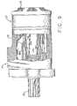
- FIG. 1 is an axial cross section of a fluid pressure actuated motor of the type to which the present invention may be applied, and which is illustrated and described in greater detail in U. S. Pat. No. 3,572,983, assigned to the assignee of the present invention. It should be understood that the term "motor" when applied to such fluid pressure devices is also intended to encompass the use of such devices as pumps.
- the hydraulic motor generally designated 11, comprises a plurality of sections secured together, such as by a plurality of bolts 12 (shown only in FIGS. 2 and 3).
- the motor 11 includes a shaft support casing 13, a wear plate 15, a gerotor displacement mechanism 17, a port plate 19, and a valve housing portion 21.
- the gerotor displacement mechanism 17 is well known in tne art and will be described only briefly herein. More specifically, in the subject embodiment, the displacement mechanism 17 is a Geroler displacement mechanism comprising an internally-toothed assembly 23.
- Eccentrically disposed within the internally-toothed assembly 23 is an externally-toothed rotor member 27, typically having one less external tooth than the number of cylindrical teeth 25, thus permitting the rotor member 27 to orbit and rotate relative to the internally-toothed assembly 23.
- the relative orbital and rotational movement between the assembly 23 and the rotor 27 defines a plurality of expanding and contracting volume chambers 29.
- the motor 11 includes an input-output shaft 31 positioned within the shaft support casing 13 and rotatably supported therein by suitable bearing sets 33 and 35.
- the shaft 31 includes a set of internal, straight splines 37, and in engagement therewith is a set of external, crowned splines 39 formed on one end of a main drive shaft 41.
- Disposed at the opposite end of the main drive shaft 41 is another set of external, crowned splines 43, in engagement with a set of internal, straight splines 45, formed on the inside diameter of the externally-toothed rotor member 27. Therefore, in the subject embodiment, because the internally-toothed assembly 23 includes six internal teeth 25, seven orbits of the rotor member 27 result in one complete rotation thereof, and as a result, one complete rotation of the main drive shaft 41 and the input-output shaft 31.
- a set of external splines 47 formed about one end of a valve drive shaft 49 which has, at its opposite end, another set of external splines 51 in engagement with a set of internal splines 53 formed about the inner periphery of a valve mem- member 55.
- the valve member 55 is rotatably disposed within the valve housing 21, and the valve drive shaft 49 is splined to both the rotor member 27 and the valve member 55 in order to maintain proper valve timing, as is generally well known in the art.
- the valve housing 21 includes a fluid port 57 in communication with an annular chamber 59 which surrounds the annular valve member 55.
- the valve housing 21 also includes another fluid port (not shown) which is in fluid communication with a fluid chamber 61.
- the valve member 55 defines a plurality of alternating valve passages 63 and 65, the valve passages 63 being in continuous fluid communication with the annular chamber 59, and the valve passages 65 being in continuous fluid communication with the chamber 61.
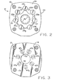
- the port plate 19 defines a plurality of fluid passages 67, each of which is disposed to be in continuous fluid communication with the adjacent volume chamber 29. As may best be seen in FIG. 3, the cross sectional area of each of the fluid passages 67 is smallest adjacent the valve member 55 and largest adjacent the volume chamber 29.
- pressurized fluid entering the fluid port 57 will flow through the annular chamber 59, then through each of the valve passages 63, and through the fluid passages in the port plate 19 which are identified as 67a, 67b, and 67c. This fluid will then enter the expanding volume chambers identified as 29a, 29b, and 29c, respectively.
- the above-described flow of pressurized fluid will result in movement of the rotor member 27, as viewed in FIG.
- fluid exhausted from the contracting volume chambers 29d, 29e, and 29f is communicated through the fluid passages 67d, 67e, and 67f, respectively.
- Exhaust fluid flowing out of the fluid passages 67 enters the respective valve passages 65 and flows into the fluid chamber 61, then to the fluid port not shown in FIG. 1, and from there, to the reservoir.
- the operation of the fluid motor described above is conventional, and generally well understood by those skilled in the art.
- valve surfaces 71 and 73 are flat, planar surfaces oriented substantially perpendicular to the axis of the motor 11.
- the valve surfaces it is within the scope of the present invention for the valve surfaces to be cylindrical, as would be the case in a fluid motor of the type referred to as a "spool valve" motor, the general construction of which is illustrated in U. S. Pat. No. 3,606,598, assigned to the assignee of the present invention, and incorporated herein by reference. The application of the present invention to a spool valve motor will be illustrated and described subsequently.
- the valve surface 71 of the-port plate 19 defines a plurality of secondary fluid passages 75, each of which is in open fluid communication with its adjacent fluid passage 67, and extends radially inwardly therefrom.
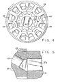
- the valve surface 73 of the valve member 55 defines a plurality of secondary fluid passages 77, each of which is preferably disposed between an adjacent fluid passage 63 and an adjacent fluid passage 65.
- Each of the fluid passages 77 is in fluid communication with a central, open region of the motor 11 within which is disposed the valve drive shaft 49, and extends radially outwardly from this central, open region.
- FIG. 5 which illustrates the flow path established by the fluid passages 75 and 77
- the cross section shown in FIG. 5 is not strictly correct, but is intended to illustrate relative positions of various elements. More specifically, it will be noted by viewing FIG. 4 that none of the fluid passages 77 would actually appear in the same cross section with one of the fluid passages 65, or with one of the fluid passages 63. However, in view of the fact that the valve member 55 is shown on a larger scale in FIG. 4 than is the port plate 19 in FIG. 3, the cross section in FIG. 5 is intended to illustrate, in one view, the relative positions of the fluid passages 65 (or 63) and 67 during communication, as well as to illustrate the "secondary" fluid path provided by the fluid passages 75 and 77.
- FIG. 2 it may be seen that the rotor member 27 is in such a position that the volume chamber 29g is at its "minimum volume position".
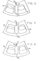
- the position of the displacement mechanism 17 shown in FIG. 2 corresponds to the relative position of the valve surfaces 71 and 73 illustrated in FIG. 7.
- the fluid passages 67a, 67o, and 67c are receiving pressurized fluid through the respective valve passages 63, while exhaust fluid is being communicated from the fluid passages 67d,.
- the fluid drawn through the secondary passages 75 and 77 by the expanding volume chamber 29g as described above is basically the same fluid which, during the previous instant, had been exhausted to prevent the pressure surge as the volume chamber 29g completed its contraction.
- the secondary fluid passages 75 and 77 have been described as providing fluid communication between the fluid passage 67g and the central, open region of the port plate 19 which, as is shown in FIG. 1 and as is well known in the art, is in fluid communication with the region in which the main drive shaft 41 is located. This entire central region communicates through a pair of angled passages 81, defined by the output shaft 31, with the region in which the bearing sets 33 and 35 are disposed.
- each of the secondary fluid passages 77 should be in fluid communication with a source of relatively lower pressure fluid, and in the devices of the type to which the present invention would be applied, the case drain "circuit" is available as such a source.
- the term "source of relatively lower pressure fluid” is not intended to indicate any particular pressure level, but merely that the invention is better able to relieve pressure surges when the fluid passages 77 are connected to a source of fluic at a pressure low enough to proviae a substantial pressure differential across the seconaary passages 75 and 77.
- the operation of the present invention has been aescribed with respect to the operating condition wherein the volume chamber 29g is approaching its minimum volume condition, it should be clearly understood that during one complete orbit of the rotor member 27, each of the volume chambers 29a through 29g goes through the same cycle of contracting, reaching its minimum volume position, then expanding as was described for the volume chamber 29g.
- each of the fluid passages 75 is permitted to communicate with its respective fluia passage 77.
- this permitted communication occurs as each volume chamber is at approximately its minimum volume position, and fluid communication is blocked between the respective fluid passage 67, and both of the adjacent valve passages 63 and 65, as has been described above.
- each of the fluid passages 75 will communicate with a different one of the fluia passages 77, until after six complete orbits of the rotor member 27, and one complete rotation thereof, the valve member 55 has also made one complete rotation, and each of the fluid passages 75 again communicates with the same one of the fluid passages 77, in much the same manner that each of the valve passages 63 and 65 again communicates with the same one of the fluid passages 67.
- consiaeration has been given only to the condition of each of the volume chambers as it approaches the minimum volume position. If that were the sole function of the present invention, only six of the fluid passages 77 would be required in the subject embodiment. However, it may be seen in FIG. 4 that there are 12 of the fluid passages 77, corresponding to twice the number of external teeth on the rotor member 27. Although not an essential feature of the present invention, the additional fluid passages 77 make it possible for the preferred embodiment of the invention to perform a similar function, as each of the volume chambers approaches the maximum volume position.
- the problems which occur i.e., trapping and cavitation
- the problems which occur occur in the reverse order when the volume chamber is at the maximum volume position. If the volume chamber expands after the fluid passage 67 is blocked from communication with the valve passage 63, cavitation can occur within the volume chamber, and secondly, if the volume chamber begins to contract before there is fluid communication established between the fluid passage 67 and the valve passage 65, trapping of fluid within the volume chamber can occur.
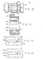
- FIGS. 9 through 13 an alternative embodiment will be described in which the present invention is being utilized in a spool valve motor and in which functionally equivalent elements bear the same numerals as in FIGS. 1 through 8, plus 100. It may be seen by viewing FIGS. 10, 12, and 13 that the primary difference between this embodiment of the invention and the embodiment shown in FIGS. 1 through 8 is that the fluid passages 177 comprise drilled holes extending radially from the outer surface of the rotatable valve member 155 into the interior of the hollow valve member 155, which is analogous to the central, open region defined by the port plate 19 in the first embodiment.
- FIG. 12 corresponds approximately to FIG. 6, i.e., it illustrates the condition in which the volume chamber 129g (not shown) is contracting, and exhaust fluid is flowing out of the fluid passage 167g, through the valve passage 165, and into the annular chamber 161.
- FIG. 13 corresponds approximately to FIG. 7, i.e., it illustrates the condition in which the volume chamber 129g is at its minimum volume position, the fluid passage 167 is no longer in fluid communication with the valve passage 165, and is not yet in fluid communication with the valve passage 163.
- the fluid passage 177 has moved into fluid communication with the fluid passage 175 to relieve any pressure surges resulting from the final contraction of the volume chamber 129g.
- the mating valve surfaces are flat, planar surfaces oriented substantially perpendicular to the axis of the device, or are cylindrical surfaces oriented substantially parallel to the axis of the device, it may be seen that the present invention may be used advantageously.
- the invention has been described in detail sufficient to enable one of ordinary skill in the art to make and use the same. Other modifications and alterations of the preferred embodiments will occur to those skilled in the art upon a reading and understanding of the specification, and it is my intention to include all such modifications and alterations as part of my invention, insofar as they come within the scope of the appended claims.
Landscapes
- Engineering & Computer Science (AREA)
- Mechanical Engineering (AREA)
- General Engineering & Computer Science (AREA)
- Hydraulic Motors (AREA)
- Rotary Pumps (AREA)
Applications Claiming Priority (2)
| Application Number | Priority Date | Filing Date | Title |
|---|---|---|---|
| US06/118,264 US4343600A (en) | 1980-02-04 | 1980-02-04 | Fluid pressure operated pump or motor with secondary valve means for minimum and maximum volume chambers |
| US118264 | 2002-04-08 |
Publications (3)
| Publication Number | Publication Date |
|---|---|
| EP0033544A2 true EP0033544A2 (fr) | 1981-08-12 |
| EP0033544A3 EP0033544A3 (en) | 1981-08-26 |
| EP0033544B1 EP0033544B1 (fr) | 1984-07-25 |
Family
ID=22377522
Family Applications (1)
| Application Number | Title | Priority Date | Filing Date |
|---|---|---|---|
| EP81100765A Expired EP0033544B1 (fr) | 1980-02-04 | 1981-02-03 | Machine à fluide à engrenage à axe interne ayant des moyens de distribution |
Country Status (4)
| Country | Link |
|---|---|
| US (1) | US4343600A (fr) |
| EP (1) | EP0033544B1 (fr) |
| JP (1) | JPS56135760A (fr) |
| DE (1) | DE3164938D1 (fr) |
Cited By (3)
| Publication number | Priority date | Publication date | Assignee | Title |
|---|---|---|---|---|
| EP0046293B1 (fr) * | 1980-08-20 | 1985-07-31 | Eaton Corporation | Appareil rotatif à pression de fluide à mécanisme de positionnement de soupape |
| EP0153076A1 (fr) * | 1984-02-17 | 1985-08-28 | Eaton Corporation | Moteur gérotor et circuit de lubrification annexe |
| GB2240365A (en) * | 1990-01-29 | 1991-07-31 | White Hollis Newcomb Jun | Reduced sized rotary hydraulic motor |
Families Citing this family (7)
| Publication number | Priority date | Publication date | Assignee | Title |
|---|---|---|---|---|
| DK162791C (da) * | 1983-04-04 | 1992-04-27 | Eaton Corp | Tandhjulsmaskine, isaer hydraulisk tandhjulsmotor |
| US4592704A (en) * | 1984-03-05 | 1986-06-03 | Eaton Corporation | Motor with improved low-speed operation |
| US4741681A (en) | 1986-05-01 | 1988-05-03 | Bernstrom Marvin L | Gerotor motor with valving in gerotor star |
| US6019584A (en) | 1997-05-23 | 2000-02-01 | Eaton Corporation | Coupling for use with a gerotor device |
| US6155808A (en) | 1998-04-20 | 2000-12-05 | White Hydraulics, Inc. | Hydraulic motor plates |
| DE10204103C1 (de) * | 2002-02-01 | 2003-10-30 | Sauer Danfoss Nordborg As Nord | Hydraulikmotor |
| WO2017209867A1 (fr) * | 2016-06-01 | 2017-12-07 | Parker-Hannifin Corporation | Optimisation de soupape à disque de moteur hydraulique |
Family Cites Families (6)
| Publication number | Priority date | Publication date | Assignee | Title |
|---|---|---|---|---|
| US2956506A (en) * | 1955-11-21 | 1960-10-18 | Robert W Brundage | Hydraulic pump or motor |
| US3289542A (en) * | 1963-10-29 | 1966-12-06 | Lawrence Machine & Mfg Company | Hydraulic motor or pump |
| DE1553004C3 (de) * | 1966-07-19 | 1974-09-12 | Danfoss A/S, Nordborg (Daenemark) | Steuerdrehschiebereinrichtung an einer Rotationskolbenmaschine |
| US3514234A (en) * | 1968-06-10 | 1970-05-26 | Char Lynn Co | Fluid operated devices |
| DE2124006C3 (de) * | 1971-05-14 | 1979-03-01 | Danfoss A/S, Nordborg (Daenemark) | Rotationskolbenmaschine für Flüssigkeiten mit einem außenverzahnten und einem innenverzahnten Zahnrad |
| US3862814A (en) * | 1973-08-08 | 1975-01-28 | Eaton Corp | Lubrication system for a hydraulic device |
-
1980
- 1980-02-04 US US06/118,264 patent/US4343600A/en not_active Expired - Lifetime
-
1981
- 1981-02-03 DE DE8181100765T patent/DE3164938D1/de not_active Expired
- 1981-02-03 EP EP81100765A patent/EP0033544B1/fr not_active Expired
- 1981-02-04 JP JP1558181A patent/JPS56135760A/ja active Pending
Cited By (4)
| Publication number | Priority date | Publication date | Assignee | Title |
|---|---|---|---|---|
| EP0046293B1 (fr) * | 1980-08-20 | 1985-07-31 | Eaton Corporation | Appareil rotatif à pression de fluide à mécanisme de positionnement de soupape |
| EP0153076A1 (fr) * | 1984-02-17 | 1985-08-28 | Eaton Corporation | Moteur gérotor et circuit de lubrification annexe |
| GB2240365A (en) * | 1990-01-29 | 1991-07-31 | White Hollis Newcomb Jun | Reduced sized rotary hydraulic motor |
| GB2240365B (en) * | 1990-01-29 | 1994-10-12 | White Hollis Newcomb Jun | Orbiting valve hydraulic motor |
Also Published As
| Publication number | Publication date |
|---|---|
| EP0033544A3 (en) | 1981-08-26 |
| DE3164938D1 (en) | 1984-08-30 |
| US4343600A (en) | 1982-08-10 |
| EP0033544B1 (fr) | 1984-07-25 |
| JPS56135760A (en) | 1981-10-23 |
Similar Documents
| Publication | Publication Date | Title |
|---|---|---|
| EP0116217B1 (fr) | Moteur à engrenages internes pour deux vitesses | |
| US4715798A (en) | Two-speed valve-in star motor | |
| US3453966A (en) | Hydraulic motor or pump device | |
| US3289602A (en) | Fluid pressure device | |
| US3288034A (en) | Rotary motor or pump | |
| EP0217422B1 (fr) | Moteur gérotor et circuit de lubrification annexe | |
| US3272142A (en) | Porting and passage arrangement for fluid pressure device | |
| US4343600A (en) | Fluid pressure operated pump or motor with secondary valve means for minimum and maximum volume chambers | |
| US3597128A (en) | Hydraulic device having hydraulically balanced commutation | |
| US3547565A (en) | Rotary device | |
| EP0046293B1 (fr) | Appareil rotatif à pression de fluide à mécanisme de positionnement de soupape | |
| US3910732A (en) | Gerotor pump or motor | |
| US5516268A (en) | Valve-in-star motor balancing | |
| US4502855A (en) | Rotary piston machine with parallel internal axes | |
| US5593296A (en) | Hydraulic motor and pressure relieving means for valve plate thereof | |
| EP0412403B1 (fr) | Dispositif rotatif à pression de fluide et plaque de soupape stationnaire perfectionnée | |
| US3456559A (en) | Rotary device | |
| US3352247A (en) | Fluid pressure device with dual feed and exhaust | |
| US3011447A (en) | Hydraulic pump or motor | |
| US4334843A (en) | Gerotor machine with valve plates attached to wheel gear | |
| US3554675A (en) | Hydraulic rotary-pressure device | |
| US4323335A (en) | Distributor valve for hydraulic planetary piston machine | |
| US3444819A (en) | Hydraulic motors and pumps | |
| US4645438A (en) | Gerotor motor and improved lubrication flow circuit therefor | |
| EP0555909B1 (fr) | Pompe rotative avec boîtier de pompe simplifié |
Legal Events
| Date | Code | Title | Description |
|---|---|---|---|
| PUAI | Public reference made under article 153(3) epc to a published international application that has entered the european phase |
Free format text: ORIGINAL CODE: 0009012 |
|
| PUAL | Search report despatched |
Free format text: ORIGINAL CODE: 0009013 |
|
| AK | Designated contracting states |
Designated state(s): DE FR GB |
|
| AK | Designated contracting states |
Designated state(s): DE FR GB |
|
| 17P | Request for examination filed |
Effective date: 19811030 |
|
| GRAA | (expected) grant |
Free format text: ORIGINAL CODE: 0009210 |
|
| AK | Designated contracting states |
Designated state(s): DE FR GB |
|
| REF | Corresponds to: |
Ref document number: 3164938 Country of ref document: DE Date of ref document: 19840830 |
|
| ET | Fr: translation filed | ||
| PGFP | Annual fee paid to national office [announced via postgrant information from national office to epo] |
Ref country code: DE Payment date: 19841212 Year of fee payment: 5 |
|
| PLBE | No opposition filed within time limit |
Free format text: ORIGINAL CODE: 0009261 |
|
| STAA | Information on the status of an ep patent application or granted ep patent |
Free format text: STATUS: NO OPPOSITION FILED WITHIN TIME LIMIT |
|
| 26N | No opposition filed | ||
| PG25 | Lapsed in a contracting state [announced via postgrant information from national office to epo] |
Ref country code: FR Free format text: LAPSE BECAUSE OF NON-PAYMENT OF DUE FEES Effective date: 19881028 |
|
| PG25 | Lapsed in a contracting state [announced via postgrant information from national office to epo] |
Ref country code: DE Effective date: 19881101 |
|
| GBPC | Gb: european patent ceased through non-payment of renewal fee | ||
| PG25 | Lapsed in a contracting state [announced via postgrant information from national office to epo] |
Ref country code: GB Free format text: LAPSE BECAUSE OF NON-PAYMENT OF DUE FEES Effective date: 19881118 |
|
| REG | Reference to a national code |
Ref country code: FR Ref legal event code: ST |