EP0033603A2 - Filterplatte - Google Patents
Filterplatte Download PDFInfo
- Publication number
- EP0033603A2 EP0033603A2 EP81300205A EP81300205A EP0033603A2 EP 0033603 A2 EP0033603 A2 EP 0033603A2 EP 81300205 A EP81300205 A EP 81300205A EP 81300205 A EP81300205 A EP 81300205A EP 0033603 A2 EP0033603 A2 EP 0033603A2
- Authority
- EP
- European Patent Office
- Prior art keywords
- filter
- filter plate
- planar member
- elongated
- liquid
- Prior art date
- Legal status (The legal status is an assumption and is not a legal conclusion. Google has not performed a legal analysis and makes no representation as to the accuracy of the status listed.)
- Ceased
Links
Images

Classifications
-
- B—PERFORMING OPERATIONS; TRANSPORTING
- B01—PHYSICAL OR CHEMICAL PROCESSES OR APPARATUS IN GENERAL
- B01D—SEPARATION
- B01D25/00—Filters formed by clamping together several filtering elements or parts of such elements
- B01D25/12—Filter presses, i.e. of the plate or plate and frame type
- B01D25/127—Filter presses, i.e. of the plate or plate and frame type with one or more movable filter bands arranged to be clamped between the press plates or between a plate and a frame during filtration, e.g. zigzag endless filter bands
- B01D25/1275—Filter presses, i.e. of the plate or plate and frame type with one or more movable filter bands arranged to be clamped between the press plates or between a plate and a frame during filtration, e.g. zigzag endless filter bands the plates or the frames being placed in a non-vertical position
-
- B—PERFORMING OPERATIONS; TRANSPORTING
- B01—PHYSICAL OR CHEMICAL PROCESSES OR APPARATUS IN GENERAL
- B01D—SEPARATION
- B01D25/00—Filters formed by clamping together several filtering elements or parts of such elements
- B01D25/30—Feeding devices ; Discharge devices
Definitions
- THIS INVENTION relates to liquid filtering apparatus of the separable plate type and more particularly to an improved filter plate for such apparatus.
- a filter plate for a liquid filtering apparatus comprising a stack of filter plates on a base support, means for separating the plates to allow the installation of sheets of filter media between adjacent plates and means for closing the plates together to form inlet chambers and colletion chambers on opposite sides of each said sheet of filter media, said filter plate comprising: a central planar member; side walls and end walls connected to the sides and ends of said planar member and connected together at their ends to form a continuous rectangular barrier that extends above and below said planar member, said barrier forming an inlet chamber for dirty liquid below said planar member and a collection chamber above said planar member.
- a plurality of filter plates is arranged in a vertical stack and a mechanism is provided for separating the plates to allow for the insertion of sheets of filter media between adjacent plates. Thereafter, the plates are moved back together to seal against the various filter media sheets and they form an inlet chamber for dirty liquid on the upper side of each sheet and a collection chamber for clean filtrate on the lower side of each sheet.
- a manifold of conduits for a common inlet pipe is connected to the inlet chambers and another manifold of conduits for a common outlet pipe is connected to the collection chambers of the plates.
- Another object of the invention is to provide a filter plate that distributes liquid flowing into the collection chamber in such a manner that no erosion or disturbance of the filter cake will occur, even at maximum flow rates.
- a filter plate for a liquid filtering apparatus comprising a stack of filter plates on a base support, means for separating the plates to allow the installation of sheets of filter media between adjacent plates and means for closing the plates together to form inlet chambers and collection chambers on opposite sides of each said sheet of filter media
- said filter plate comprising: a central planar member; side walls and end walls connected to the sides and ends of said planar member and connected together at their ends to form a continuous rectangular barrier that extends above and below said planar member, said barrier forming an inlet chamber for dirty liquid below said planar member and a collection chamber above said planar member wherein elongated means are attached to said side walls for forming two elongated manifold chambers on opposite sides of each filter plate; inlet openings in one said side wall for allowing the passage of dirty liquid from one of said elongated chambers into the space on the one side of said planar member and openings in the other said side wall for allowing the passage of clean liquid from the other side of said planar
- Said side walls and end walls may be nominally vertical relative to said central planar member, sloped inner surfaces on said side walls and preferably also on said end walls extending from a level below said central planar member to their bottom inside edges, whereby filter cake that normally builds up on the filter media during operation of the filter is prevented from adhering to the inner surfaces of said side walls and the overall filtering area for the filter plate is maximized.
- Said inner surface may be sloped outwardly at around 60° and extends above the bottom edges of said walls for a distance of around 2.5 cms (1 inch).
- said spaced apart liquid distribution means are located on the underside of said planar member and comprise elongated cross members having their ends fixed to opposite side walls each said member being aligned with a said inlet opening and providing elongated narrow outlets for dirty liquid within said inlet chamber.
- Said inlet openings for dirty liquid in one said side wall may be elongated and spaced apart near the lower edge of the side wall.
- Each said liquid distribution cross member may have a channel shaped cross section and is aligned with a said inlet opening, said elongated narrow outlets therefrom being formed by spaces between the edges of said channel shaped cross member and the underside of said central planar member.
- said elongated means for forming said manifold chambers comprise channel members having closed ends and attached to said side walls by weldments along the edges of the channel legs.
- a filter incorporating filter plates normally comprises a plurality of intermediate filter plates in combination with a bottom plate supported on a base structure and a top plate connected to a suitable lifting jack mechanism.
- the plates are linked together in a stacked arrangement so that they can be separated to allow for installation and/or advancement of sheets of filter media between plates and thereafter a compression of the plates together to seal inlet and collection chambers on opposite sides of each media sheet.
- An intermediate filter plate in accordance with the invention comprises generally a central rectangular planar member of rigid and impervious material surrounded on all sides by a continuous wall that extends above and below the planar member. Fixed to each opposite side wall member is a channel forming an elongated manifold chamber.
- a conduit fitting is attached to an outside opening in each channel which facilitates the flow of dirty liquid into one elongated chamber and the removal of clean liquid from the other one.
- a series of spaced apart openings is provided in each side wall, a first series providing for the flow of clean liquid into the inlet chamber below the central planar member and a second series on the other side wall providing for the flow of dirty liquid from the collection chamber.
- An inlet liquid distribution member is aligned with each of the first series of openings to control the flow of incoming liquid across the inlet chamber and the filter media below.
- the lower inside surface of the side walls is sloped downwardly and outwardly to form a peripheral undercut area.
- filter cake is allowed to build up normally to increase the overall effective filtering area of the filter plate, but it provides an even more important advantage of preventing filter cake from building up on the sloped side wall surface. This enables the filter to operate efficiently and eliminates costly and time consuming cleanup procedures between filtering cycles.
- Figure 1 shows a filter apparatus 20 utilizing a series of filter plates 22 in accordance with the present invention.
- the filter plates are arranged horizontally in a stack, supported by a frame 24 and controlled by a mechanism including a power jack 26 for separating and closing them.
- a supply rack 28 On one side of the plates is a supply rack 28 for a series of rolls 30 of filter media and on the opposite side of the plates is an extractor mechanism 32 for removing used filter media and placing new media into position between plates.
- the filter media may be a suitable paper or woven fabric of a type well known in the art, and a sheet of filter media from each supply roll extends between one pair of adjacent plates to the extractor mechanism.
- inlet and outlet chambers are formed by them on opposite sides of the filter sheet so that dirty liquid fills the inlet chamber of one plate and clean filtrate collects in the outlet chamber of the next lower plate.
- Suitable conduits or hoses 34 extend to the filter plates on one side thereof to supply dirty liquid to their inlet chambers and these hoses are connected to a common or main inlet 36 for the dirty liquid.
- Similar hoses are connected to the opposite sides of the filter plates to remove the filtrate from their outlet chambers and these latter hoses are supplied to a common outlet pipe (not shown).
- the extractor mechanism 32 may be of any suitable type, such as shown in U.S.A. Patent Specification No.3,608,734, or it may comprise a series of drive rollers 38, as shown, each having a pinch wheel mechanism 40, such as described in greater detail in copending European Patent Application No.
- each filter plate 22 is comprised of a main, central, rectangular planar member 42 of a rigid material, such as steel or aluminium, and having a uniform thickness.
- a main, central, rectangular planar member 42 of a rigid material, such as steel or aluminium, and having a uniform thickness.
- a series of cylindrical support horns 43 Spaced apart along the centre line of each member 42 and extending above and below it to the same level as the side and end wall members, is a series of cylindrical support horns 43. These horns provide additional columnar strength and prevent any excessive flexure of the members 42.
- each planar member On the upper side of each planar member, which is normally covered by a sheet of filter media 30 when the filter is in operation, the upwardly extending side and end members form a collection chamber 48 for the clean filtrate.
- a removable grate 49 is provided in the upper collection chamber 48 of each filter plate 22, preferably covered by a perforated sheet 51 of metal or some other material for supporting the filter media 30.
- each planar member 42 On the lower side of each planar member 42 the downwardly extending lower portions of the side and end members form an inlet chamber 50 for the dirty liquid to be filtered.
- the lower inlet chamber of each plate is matched with an upper collection chamber of the plate below.
- top plate 52 and a bottom plate 54 are provided; as shown in Figure 1.
- the top plate is attached to the lifting or power jack mechanism 26 and has a central planar member with side and end wall members that provide only an inlet chamber for dirty liquid.
- the bottom plate 54 which is fixed to a filter base support 56 also has a central member with side and end wall members that form only a collection chamber for clean filtrate. Since these top and bottom plates are essentially the same as upper and lower portions of the full plate 22, they are not shown in detail.
- dirty liquid to be filtered is supplied from an inlet conduit 36 through flexible hoses 34 to the top plate 52 and to one side of each intermediate filter plate 22 and clean filtrate is removed by similar flexible hoses (not shown) on the opposite sides of the intermediate filter plates and from the bottom plate.
- the hoses on both opposite sides are attached to pairs of suitable flanged fittings 58 which are fixed to the sides of the filter plate.
- each pair of these latter hose fittings is fixed to a channel member 60 that is welded to a side wall member 44 by weldments along the edges of the channel legs.
- Each channel member is closed at its ends to form an elongated chamber 62 that extends substantially the entire length of the plate 22 and over a series of spaced apart openings or slots in its sidewalls.
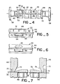
- a series of such slots 64 provided for incoming dirty liquid, is located just below the central planar member to provide access to the inlet chamber 50 (See Figure 5).
- a similar series of slots 66 is located above the central planar 42 member to provide openings to the collection chambers 52 of each plate.
- each inlet slot 64 Located around each inlet slot 64, as shown in Figure 5, and extending transversely across each filter plate, is a series of liquid distribution channels 68. Both ends of each of these channels are welded to the inside surface of the opposite side walls 44 below the central planar member and therefore they serve to strengthen the filter plate and make it more rigid.
- a primary purpose of each channel 68 is to provide a means for distributing incoming dirty liquid at a relatively high flow rate but without distributing, by erosion, the filter cake that is normally present on the media below.
- the upper edges of the opposite flanges for each channel are spaced just below the central planar member to form a uniform, narrow (e.g. 4.7 mm(3/16")) gap 70 across the width of the filter plate.
- each filter plate At the lower edge of the connected side and end wall members for each filter plate is a groove 72 which becomes adjacent to the sheet of filter media when the filter is in operation.
- the groove for each filter plate is connected through a side port 73 to a low pressure fluid source, e.g. a partial vacuum source, (not shown) so that it can provide for sealing of the plate against the media.
- a low pressure fluid source e.g. a partial vacuum source
- the lower portions of all the side wall and end wall members are tapered by a sloped surface 74 that starts the inner wall surface a short distance from their bottom edges (e.g. 2.5 cms (one inch)) and just below the transverse channels 68 and diverges downwardly and outwardly at a uniform angle (e.g., 60 0 ).
- This sloped surface 74 which extends completely around the lower inner wall of the inlet chamber for each filter plate is a feature that provides several advantages for the described filter 20. For one thing, it prevents a filter cake 76, that normally builds up within each inlet chamber, from contacting and adhering to the wall surface of each filter plate. This was a common occurrence with prior art filters having vertical side walls at this point.
- the side walls of the inlet chambers for the plates of the presently described filter are always substantially clean and there is no build-up of filter cake requiring a time- consuming removal procedure.
- the normal flow of liquid through the filter media is substantially vertical and as the filter cake builds up, it normally tapers in thickness within the undercut peripheral area of each filter plate.
- the cake thickness is substantially zero and none of it builds up on the sloped wall surface 74.
- sloped wall surface 74 provides a substantial increase in effective filtering area for each filter plate with no additional structural requirements. For example, assuming a filter plate having an inlet chamber with width and length dimensions of 1.22 metres (4.8 inches) by 2.44 metres (96 inches) and assuming that the sloped wall surface provides a bordering perimeter strip 1.2 cms (0.5 inches) in width, the increased filtering area per plate would amount to 878 sq.cms (144 square inches) which is a significant increase that increased efficient utilization of the filter 20.
- each plate is thus provided with six lifting and alignment clips 78 which are fixed to opposite ends of each side wall 44 and cooperate with the linkage and alignment elements in the well known manner.
- the construction of the filter plate 22 is relatively simple and can be accomplished using standard production methods with a minimum of labour and without expensive special tooling.
Landscapes
- Chemical & Material Sciences (AREA)
- Chemical Kinetics & Catalysis (AREA)
- Filtration Of Liquid (AREA)
Applications Claiming Priority (2)
| Application Number | Priority Date | Filing Date | Title |
|---|---|---|---|
| US11496880A | 1980-01-24 | 1980-01-24 | |
| US114968 | 1980-01-24 |
Publications (2)
| Publication Number | Publication Date |
|---|---|
| EP0033603A2 true EP0033603A2 (de) | 1981-08-12 |
| EP0033603A3 EP0033603A3 (de) | 1982-03-17 |
Family
ID=22358562
Family Applications (1)
| Application Number | Title | Priority Date | Filing Date |
|---|---|---|---|
| EP81300205A Ceased EP0033603A3 (de) | 1980-01-24 | 1981-01-16 | Filterplatte |
Country Status (2)
| Country | Link |
|---|---|
| EP (1) | EP0033603A3 (de) |
| JP (1) | JPS56105710A (de) |
Cited By (2)
| Publication number | Priority date | Publication date | Assignee | Title |
|---|---|---|---|---|
| US5338443A (en) * | 1992-06-29 | 1994-08-16 | Henry Filters, Inc. | Filter media tensioning device |
| CN114849339A (zh) * | 2022-05-18 | 2022-08-05 | 马鞍山格林环保科技有限公司 | 一种带有自动排液系统的盘式真空过滤机 |
Family Cites Families (4)
| Publication number | Priority date | Publication date | Assignee | Title |
|---|---|---|---|---|
| DE1461500B1 (de) * | 1963-10-15 | 1970-04-02 | Uk Ni I Ki Khim Mash | Etagendruckfilter |
| DE1949114C3 (de) * | 1968-09-30 | 1975-07-24 | Ukrainskij Nautschno-Issledowatelskij I Konstruktorskij Institut Chimitscheskowo Maschinostrojenija, Charkow (Sowjetunion) | Etagendruckfilter mit horizontal angeordneten Filterplatten |
| DE2758434A1 (de) * | 1977-03-21 | 1978-09-28 | Schneider Co Inc J R | Filtereinrichtung |
| AU525535B2 (en) * | 1978-05-10 | 1982-11-11 | Parmentier, A.H. | Filter press plate + frame |
-
1981
- 1981-01-16 EP EP81300205A patent/EP0033603A3/de not_active Ceased
- 1981-01-19 JP JP625981A patent/JPS56105710A/ja active Pending
Cited By (2)
| Publication number | Priority date | Publication date | Assignee | Title |
|---|---|---|---|---|
| US5338443A (en) * | 1992-06-29 | 1994-08-16 | Henry Filters, Inc. | Filter media tensioning device |
| CN114849339A (zh) * | 2022-05-18 | 2022-08-05 | 马鞍山格林环保科技有限公司 | 一种带有自动排液系统的盘式真空过滤机 |
Also Published As
| Publication number | Publication date |
|---|---|
| EP0033603A3 (de) | 1982-03-17 |
| JPS56105710A (en) | 1981-08-22 |
Similar Documents
| Publication | Publication Date | Title |
|---|---|---|
| US7820062B2 (en) | Tertiary filter | |
| CA1073823A (en) | Grouped cylindrical filters on manifolds leading to a header | |
| CA1238862A (en) | Edible oil cleaner | |
| CN87104231A (zh) | 超滤装置 | |
| US5071546A (en) | Filtering device, particularly a suction filter | |
| US3968040A (en) | Plate filter with horizontally arranged bilaterally acting filters | |
| DE4031627A1 (de) | Druckfilter mit kontinuierlicher abreinigung der filterflaeche | |
| US9962633B2 (en) | Disk type filtering apparatus | |
| EP0025314B1 (de) | Verfahren zur Reinigung einer Filterpresse und Filterpresse | |
| GB1565383A (en) | Cell filters | |
| US2796993A (en) | Filter plates | |
| CA1102712A (en) | Plate type filter apparatus | |
| US10016706B2 (en) | Disk type filtering apparatus | |
| CA1172969A (en) | Traveling belt filter | |
| US5445733A (en) | Plate filter | |
| DE19522133C2 (de) | Filtrationsanlage zur Trennung von Feststoffteilchen | |
| JP4140155B2 (ja) | 浸漬平膜分離装置 | |
| EP0151288B1 (de) | Bandfilter | |
| DE3306206C2 (de) | Horizontalplattenfilter | |
| US1871870A (en) | Filter construction | |
| CN221713700U (zh) | 具有滤布收放卷功能的过滤装置 | |
| EP0908213A1 (de) | Statische Anlage zum Filtern von Flüssigkeiten | |
| CN217567600U (zh) | 一种压滤机的排水装置 | |
| EP0433028B1 (de) | Zellenfilter mit einem bewegenden Rückspülsystem | |
| CN214810530U (zh) | 一种防堵塞的造纸分散机 |
Legal Events
| Date | Code | Title | Description |
|---|---|---|---|
| PUAI | Public reference made under article 153(3) epc to a published international application that has entered the european phase |
Free format text: ORIGINAL CODE: 0009012 |
|
| AK | Designated contracting states |
Designated state(s): CH DE FR GB IT |
|
| 17P | Request for examination filed |
Effective date: 19811005 |
|
| PUAL | Search report despatched |
Free format text: ORIGINAL CODE: 0009013 |
|
| RHK1 | Main classification (correction) |
Ipc: B01D 29/02 |
|
| AK | Designated contracting states |
Designated state(s): CH DE FR GB IT |
|
| STAA | Information on the status of an ep patent application or granted ep patent |
Free format text: STATUS: THE APPLICATION HAS BEEN REFUSED |
|
| 18R | Application refused |
Effective date: 19831001 |