EP0908213A1 - Statische Anlage zum Filtern von Flüssigkeiten - Google Patents
Statische Anlage zum Filtern von Flüssigkeiten Download PDFInfo
- Publication number
- EP0908213A1 EP0908213A1 EP98830580A EP98830580A EP0908213A1 EP 0908213 A1 EP0908213 A1 EP 0908213A1 EP 98830580 A EP98830580 A EP 98830580A EP 98830580 A EP98830580 A EP 98830580A EP 0908213 A1 EP0908213 A1 EP 0908213A1
- Authority
- EP
- European Patent Office
- Prior art keywords
- frames
- liquid
- tank
- plant according
- walls
- Prior art date
- Legal status (The legal status is an assumption and is not a legal conclusion. Google has not performed a legal analysis and makes no representation as to the accuracy of the status listed.)
- Granted
Links
- 238000001914 filtration Methods 0.000 title claims abstract description 82
- 239000007788 liquid Substances 0.000 title claims abstract description 60
- 230000003068 static effect Effects 0.000 title claims abstract description 13
- 238000005406 washing Methods 0.000 claims description 15
- 239000010802 sludge Substances 0.000 claims description 10
- 239000012535 impurity Substances 0.000 claims description 9
- 238000007599 discharging Methods 0.000 claims description 7
- 238000004140 cleaning Methods 0.000 claims description 6
- 238000011001 backwashing Methods 0.000 claims description 5
- 239000002184 metal Substances 0.000 claims description 3
- 238000007789 sealing Methods 0.000 claims description 3
- 238000006073 displacement reaction Methods 0.000 claims description 2
- 125000006850 spacer group Chemical group 0.000 claims description 2
- 238000005507 spraying Methods 0.000 claims description 2
- XLYOFNOQVPJJNP-UHFFFAOYSA-N water Substances O XLYOFNOQVPJJNP-UHFFFAOYSA-N 0.000 description 16
- 238000012423 maintenance Methods 0.000 description 6
- 238000000034 method Methods 0.000 description 4
- 230000000737 periodic effect Effects 0.000 description 4
- 238000000605 extraction Methods 0.000 description 3
- 239000004744 fabric Substances 0.000 description 3
- 239000000463 material Substances 0.000 description 3
- 239000007787 solid Substances 0.000 description 2
- 239000000126 substance Substances 0.000 description 2
- 230000001276 controlling effect Effects 0.000 description 1
- 238000005265 energy consumption Methods 0.000 description 1
- 238000005516 engineering process Methods 0.000 description 1
- 239000008187 granular material Substances 0.000 description 1
- 238000009434 installation Methods 0.000 description 1
- 239000002245 particle Substances 0.000 description 1
- 230000035699 permeability Effects 0.000 description 1
- 230000001105 regulatory effect Effects 0.000 description 1
- 230000000630 rising effect Effects 0.000 description 1
- 239000004576 sand Substances 0.000 description 1
- 239000007921 spray Substances 0.000 description 1
- 230000008719 thickening Effects 0.000 description 1
- 239000002699 waste material Substances 0.000 description 1
Images


Classifications
-
- B—PERFORMING OPERATIONS; TRANSPORTING
- B01—PHYSICAL OR CHEMICAL PROCESSES OR APPARATUS IN GENERAL
- B01D—SEPARATION
- B01D29/00—Filters with filtering elements stationary during filtration, e.g. pressure or suction filters, not covered by groups B01D24/00 - B01D27/00; Filtering elements therefor
- B01D29/01—Filters with filtering elements stationary during filtration, e.g. pressure or suction filters, not covered by groups B01D24/00 - B01D27/00; Filtering elements therefor with flat filtering elements
- B01D29/05—Filters with filtering elements stationary during filtration, e.g. pressure or suction filters, not covered by groups B01D24/00 - B01D27/00; Filtering elements therefor with flat filtering elements supported
-
- B—PERFORMING OPERATIONS; TRANSPORTING
- B01—PHYSICAL OR CHEMICAL PROCESSES OR APPARATUS IN GENERAL
- B01D—SEPARATION
- B01D29/00—Filters with filtering elements stationary during filtration, e.g. pressure or suction filters, not covered by groups B01D24/00 - B01D27/00; Filtering elements therefor
- B01D29/50—Filters with filtering elements stationary during filtration, e.g. pressure or suction filters, not covered by groups B01D24/00 - B01D27/00; Filtering elements therefor with multiple filtering elements, characterised by their mutual disposition
- B01D29/52—Filters with filtering elements stationary during filtration, e.g. pressure or suction filters, not covered by groups B01D24/00 - B01D27/00; Filtering elements therefor with multiple filtering elements, characterised by their mutual disposition in parallel connection
-
- B—PERFORMING OPERATIONS; TRANSPORTING
- B01—PHYSICAL OR CHEMICAL PROCESSES OR APPARATUS IN GENERAL
- B01D—SEPARATION
- B01D29/00—Filters with filtering elements stationary during filtration, e.g. pressure or suction filters, not covered by groups B01D24/00 - B01D27/00; Filtering elements therefor
- B01D29/62—Regenerating the filter material in the filter
- B01D29/64—Regenerating the filter material in the filter by scrapers, brushes, nozzles, or the like, acting on the cake side of the filtering element
- B01D29/6438—Regenerating the filter material in the filter by scrapers, brushes, nozzles, or the like, acting on the cake side of the filtering element nozzles
- B01D29/6453—Regenerating the filter material in the filter by scrapers, brushes, nozzles, or the like, acting on the cake side of the filtering element nozzles with a translational movement with respect to the filtering element
-
- B—PERFORMING OPERATIONS; TRANSPORTING
- B01—PHYSICAL OR CHEMICAL PROCESSES OR APPARATUS IN GENERAL
- B01D—SEPARATION
- B01D29/00—Filters with filtering elements stationary during filtration, e.g. pressure or suction filters, not covered by groups B01D24/00 - B01D27/00; Filtering elements therefor
- B01D29/62—Regenerating the filter material in the filter
- B01D29/66—Regenerating the filter material in the filter by flushing, e.g. counter-current air-bumps
- B01D29/68—Regenerating the filter material in the filter by flushing, e.g. counter-current air-bumps with backwash arms, shoes or nozzles
- B01D29/684—Regenerating the filter material in the filter by flushing, e.g. counter-current air-bumps with backwash arms, shoes or nozzles with a translatory movement with respect to the filtering element
Definitions
- the present invention relates to a static filtration plant for liquids.
- Liquids which contain suspended waste and dirt particles occur increasingly frequently both in the industrial sector and in the public sector.
- liquid filtration plants which are based essentially on two methods of operation: the static method and dynamic method.
- the present static filtration plants involve the use of filtering material, consisting for example of sand or granular materials, which is present in containers through which the liquids to be filtered must pass; this type of plant has the drawback that it must be stopped when it is required to perform both the periodic cleaning operations and periodic renewal of the filtering material; said plant stoppages for both maintenance and renewal result in a substantial increase in the running costs. Moreover, it is necessary to provide a standby plant to which the water to be filtered must be diverted, so that there is no interruption in operation.
- These devices operate in tanks which are divided, by means of a filter wall, into at least two chambers, one for clean water and the other for dirty water.
- the liquid to be filtered is introduced into the dirty-water chamber, flows through the filter wall and is collected as purified liquid in the clean-water chamber.
- the filter wall normally consists of a frame over which a piece of fabric is stretched so as to collect solid substances, thus increasing the resistance of the filter.
- a counter-flow washing device comprising at least one column of water jets operating on the clean-water chamber side and at least one column for removing the sludge water, situated on the opposite side.
- the counter-flow washing device is fixed onto a bridge displaceable along the wall of the filter itself, so that the moving parts are arranged above the surface level of the liquid, while the washing device suspended from the bridge is situated underneath the surface level of the liquid.
- the filter wall is sprayed on the clean-water side, by means of the column of water jets, with filtered liquid.
- the solid substances washed away together with the washing water and filtered water are sucked up, by means of the column for removing the sludge water.
- This solution has numerous drawbacks as regards the actual subject-matter of the patent and as regards the plant of the known type in which it is used.
- it consists of a filtration plant which is composed essentially of a tank divided into several fluid-tight compartments and which has the drawback, already mentioned above, of requiring stoppage thereof when it is required to perform the periodic cleaning operations.
- the device for cleaning filters first of all the assembly is fairly complex and costly because a device is necessary for each wall and, in turn, each device requires two units, one for spraying and the other for suction. Moreover the device requires an internal head for removal of the backwashing water, while the presence of a suction unit requires - in view of the low concentration of the sucked sludge - a successive compartment for thickening the sludge itself or large-volume impurities.
- the object of the present invention is that of providing a static filtration plant for liquids which eliminates the abovementioned drawbacks, which has low installation and running costs, without the need for stoppage in the case of replacement of the filtering elements, and which has a greater filter washing efficiency.
- said hopper-type sludge collection and extraction system avoids the use of apparatus which necessarily make sliding contact with the filtering walls, causing an increase in the wear and therefore the more frequent need for replacement.
- the static filtration plant for liquids characterized in that it comprises:
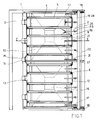
- 1 denotes a tank with a substantially parallelepiped shape inside which filtering elements, described more fully below, are inserted.
- each of the two opposite sides of the tank 1 is provided with a channel parallel to the side itself.
- Said two channels are staggered heightwise with respect to one another; the channel 2, for supplying the liquid to be clarified, is higher than the channel 3 for removal of the clarified liquid.
- a plurality of frames 4, which are all parallel with one another and vertically positioned, are fixed transversely to the internal surfaces of two opposite walls of the said tank, being separated therefrom by means of spacers 27.
- the channel 3 may be arranged on the opposite side and discharging of the filtered liquid may occur via pipes located on the bottom of the frames and connected to the channel 3.
- Each of the said frames is overall in the form of a "U” which is open upwards and with the two substantially vertical sides being fixed to the said internal walls; each frame 4 has a cross-section which is also in the form of a "U” with the open side directed towards the inside of the frame itself.
- Each of the said frames forms a support for the filtering wall 5 mounted on the respective frame 4 by means of engagement, from above, inside the U-shaped cross-section of the frame itself.
- the bottom of said cross-section is lined with a seal 6 suitable for forming a sealing element between the bottom itself and the side and bottom edges of the associated filtering wall 5.
- the seal could also be fitted onto the edges of the walls.
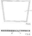
- Each of said walls is formed by one or more filtering screens 7 and by a reticular support structure 8 as can be seen from the plan view shown in Figure 6; said screens consist of material which is suitable for filtration such as, for example, cloth or fabric which is nonwoven or in any case has a low permeability, and may advantageously have a varied porosity in the vertical direction.
- Positioning of the frames 4 inside the tank 1 divides the internal volume thereof alternately into sectors 9 for filtered liquid and sectors 10 for liquid to be filtered.
- Each of the sectors 9 is in the form of a compartment closed at the bottom by a blind base 11 and laterally by a blind side 12 and by two adjacent filtering walls 5.
- the blind elements mentioned above connect the frames 4 of the said adjacent filtering walls.
- each of the sectors 9 the side which is located opposite the blind side 12 has an opening 13 which extends downwards until it reaches a level slightly higher than that of the bottom of the channel 3.
- Each opening 13 is situated opposite a discharge outlet 14, which is present on one side of the tank 1 and provided with a sluice-valve 15, said discharge outlet being connected to the channel 3.
- Each of the sectors 10, on the other hand, is open towards the bottom of the tank 1 where one or more pits are formed, each of said pits being provided with a system for removal of the impurities deposited, said system not being shown in the Figures.
- One or more guides 17 which are rectilinear and parallel with one another and the plurality of frames 4 are positioned above the tank 1.
- a plurality of unions 20 and 23 is fixed to each of the ducts 19 and 24, respectively, said plurality corresponding, in terms of both number and position, to that of the sectors 9 and the sectors 10.
- the unions corresponding to the sectors 9 containing the filtered liquid have, connected to them, a corresponding number of pipes 21 directed towards the bottom of the tank 1 and having a length substantially equivalent to the depth of the frames 4; each of the said pipes has, along its entire length, a plurality of radial nozzles 22 which are all directed towards the filtering walls 5 substantially perpendicularly with respect thereto.
- Corresponding pipes 25 are connected to unions 23 supplied by the duct 24 and descending into the sectors 10.
- the pipes 25 contain nozzles 26 with the jet directed so as to be inclined with respect to the filtering wall.
- the horizontal travel movement of the backwashing devices is performed using a pneumatic system, not shown in the Figures. This allows the speed thereof to be regulated at any moment in accordance with the individual requirements by simply metering the quantity of air supplied.
- an electric or other type of moving system which also offers the same possibilities for regulation, could be provided.
- the liquid containing impurities is made to flow into the channel 2 and from here passes into the sectors 10 present inside the tank 1.
- the channel 3 for discharging the clarified liquid is situated at a lower height than the supply channel 2, the liquid to be filtered, present inside the sectors 10, after rising up over a certain distance along all the filtering walls 5, starts to pass through, being freed of the suspended impurities.
- clarified liquid starts to fill the inside of the sectors 9; it is unable to mix with the liquid which is still dirty firstly because each of the sectors 9 is delimited by the blind bottom 11 and by the blind side 12 and also because the negative pressure existing throughout the hydraulic circuit and produced by the difference in level between the channels 2 and 3 prevents the liquid from flowing back through the filtering walls 5.
- the level eventually covers about 90% of the filtering walls, despite the washing operations performed by means of the jets emitted by the nozzles, it will be necessary to extract in pairs the filtering walls forming a single compartment 9 and replace them with other clean ones.
- the number of frames 4 must be that necessary for containing the quantities of filtering walls 5 which are required in each specific case, plus at least one extra frame.
- the latter must be of the type with a closed (non-operational) discharge outlet without filtering walls which will be installed only when it is required to perform extraordinary maintenance, replacing the filtering walls in each frame one at a time.
- the last frame will be left without filtering walls and with the discharge outlet closed, ready for any future extraordinary maintenance which may be required.
- the invention allows operation without interruption, preventing, at the same time, the discharge of unclarified liquid.
- operation is never interrupted, thus avoiding having to have a standby plant available.
- the filtered liquid is able to flow into the discharge channel 3 through the opening 13 present on one of the sides of each sector 9 and the corresponding discharge outlet 14 formed on the edge of the tank.
- this operation may be performed easily and without stopping the plant; it is necessary to close the sluice-valves 15 present in the discharge outlets 14 corresponding to the sectors 9 where said operation is to be performed, so as to prevent any mixing between the liquid to be filtered and the liquid already clarified, and then extract the filtering walls 5 to be replaced by pulling them upwards.
- an extraction system with which the plant is provided will cyclically start to operate.
- liquid is supplied to the ducts 19 and/or 24; this washing liquid flows, through the unions 20 and/or 23, to the corresponding pipes 21 and/or 25 connected to them and flows out through the nozzles 22 and/or 26 which are all directed towards the filtering walls 5.
- the spray of the washing liquid is made to cover the whole length of the filtering walls 5.
- the nozzles 22, which operate in a counterflow manner, are directed substantially with the jet perpendicular to the filtering walls, while the nozzles 26 have the co-flowing jet inclined with respect to the filtering wall so as to dislodge the debris.
- the washing operation described may be performed both from inside the sectors 9 (counterflow) and from inside the sectors 10 (co-flow) and in both directions; it is sufficient to connect the pipes 21 and 25 to the unions positioned opposite one or other group of sectors. Provision of the washing water may be performed by means of connection to the water supply network or by drawing upon the clarified liquid.
- the filtering walls 5 may also have different geometric forms so as to be able to adapt to particular requirements of the plant such as, for example, dimensions, hydraulic and filtration characteristics; however, whatever the geometric form of the said walls, it must be symmetrical with respect to the central vertical axis of the walls themselves.
- the tank 1 could be made entirely from sheet metal and, in this case, the channels 2 and 3 would be replaced by a corresponding number of ducts which are staggered identically with respect to one another heightwise and function in an identical manner. Discharging of the clarified liquid may also be performed from the bottom by means of interconnection with one or more ducts connected to a header channel.
Landscapes
- Chemical & Material Sciences (AREA)
- Chemical Kinetics & Catalysis (AREA)
- Filtration Of Liquid (AREA)
- Separation Using Semi-Permeable Membranes (AREA)
- Cyclones (AREA)
- Control Of Non-Electrical Variables (AREA)
Applications Claiming Priority (2)
| Application Number | Priority Date | Filing Date | Title |
|---|---|---|---|
| ITPR970055 | 1997-10-09 | ||
| IT97PR000055A IT1296402B1 (it) | 1997-10-09 | 1997-10-09 | Impianto di filtrazione statica dei liquidi. |
Publications (2)
| Publication Number | Publication Date |
|---|---|
| EP0908213A1 true EP0908213A1 (de) | 1999-04-14 |
| EP0908213B1 EP0908213B1 (de) | 2004-10-27 |
Family
ID=11396124
Family Applications (1)
| Application Number | Title | Priority Date | Filing Date |
|---|---|---|---|
| EP98830580A Expired - Lifetime EP0908213B1 (de) | 1997-10-09 | 1998-09-30 | Statische Anlage zum Filtern von Flüssigkeiten |
Country Status (5)
| Country | Link |
|---|---|
| EP (1) | EP0908213B1 (de) |
| AT (1) | ATE280629T1 (de) |
| DE (1) | DE69827215T2 (de) |
| ES (1) | ES2231954T3 (de) |
| IT (1) | IT1296402B1 (de) |
Cited By (3)
| Publication number | Priority date | Publication date | Assignee | Title |
|---|---|---|---|---|
| EP1219334A1 (de) * | 2000-12-21 | 2002-07-03 | Allegri Geom. Primo S.r.l. | Rückspülbarer Flüssigkeitsfilter |
| JP2020131170A (ja) * | 2019-02-25 | 2020-08-31 | クリアーシステム株式会社 | 懸濁水濾過システム及びこれに用いられる剥離モジュール |
| CN119461256A (zh) * | 2025-01-15 | 2025-02-18 | 浙江华盟电气有限公司 | 一种臭氧发生装置 |
Citations (6)
| Publication number | Priority date | Publication date | Assignee | Title |
|---|---|---|---|---|
| US4049406A (en) * | 1976-04-23 | 1977-09-20 | American Air Filter Company, Inc. | Fluid filter housing and assembly |
| FR2558078A1 (fr) * | 1984-01-13 | 1985-07-19 | Chemcut Corp | Appareil pour retirer chimiquement une matiere solide de pieces en cours de traitement chimique dans un liquide |
| GB2191109A (en) * | 1986-06-05 | 1987-12-09 | Declon Ltd | Filter for clarification of water |
| EP0274113A1 (de) * | 1987-01-07 | 1988-07-13 | INTERATOM Gesellschaft mit beschränkter Haftung | Mobile Wasserfilteranlage |
| WO1990008587A1 (de) * | 1989-01-31 | 1990-08-09 | Linde Aktiengesellschaft | Rückspülbarer filter |
| EP0701855A1 (de) * | 1994-09-16 | 1996-03-20 | DEPUR ITALIA S.r.l. | Filtersystem für Fluidströmung mit Filterreinigungsvorrichtungen |
-
1997
- 1997-10-09 IT IT97PR000055A patent/IT1296402B1/it active IP Right Grant
-
1998
- 1998-09-30 AT AT98830580T patent/ATE280629T1/de not_active IP Right Cessation
- 1998-09-30 EP EP98830580A patent/EP0908213B1/de not_active Expired - Lifetime
- 1998-09-30 ES ES98830580T patent/ES2231954T3/es not_active Expired - Lifetime
- 1998-09-30 DE DE69827215T patent/DE69827215T2/de not_active Expired - Fee Related
Patent Citations (6)
| Publication number | Priority date | Publication date | Assignee | Title |
|---|---|---|---|---|
| US4049406A (en) * | 1976-04-23 | 1977-09-20 | American Air Filter Company, Inc. | Fluid filter housing and assembly |
| FR2558078A1 (fr) * | 1984-01-13 | 1985-07-19 | Chemcut Corp | Appareil pour retirer chimiquement une matiere solide de pieces en cours de traitement chimique dans un liquide |
| GB2191109A (en) * | 1986-06-05 | 1987-12-09 | Declon Ltd | Filter for clarification of water |
| EP0274113A1 (de) * | 1987-01-07 | 1988-07-13 | INTERATOM Gesellschaft mit beschränkter Haftung | Mobile Wasserfilteranlage |
| WO1990008587A1 (de) * | 1989-01-31 | 1990-08-09 | Linde Aktiengesellschaft | Rückspülbarer filter |
| EP0701855A1 (de) * | 1994-09-16 | 1996-03-20 | DEPUR ITALIA S.r.l. | Filtersystem für Fluidströmung mit Filterreinigungsvorrichtungen |
Cited By (3)
| Publication number | Priority date | Publication date | Assignee | Title |
|---|---|---|---|---|
| EP1219334A1 (de) * | 2000-12-21 | 2002-07-03 | Allegri Geom. Primo S.r.l. | Rückspülbarer Flüssigkeitsfilter |
| JP2020131170A (ja) * | 2019-02-25 | 2020-08-31 | クリアーシステム株式会社 | 懸濁水濾過システム及びこれに用いられる剥離モジュール |
| CN119461256A (zh) * | 2025-01-15 | 2025-02-18 | 浙江华盟电气有限公司 | 一种臭氧发生装置 |
Also Published As
| Publication number | Publication date |
|---|---|
| EP0908213B1 (de) | 2004-10-27 |
| ATE280629T1 (de) | 2004-11-15 |
| ITPR970055A1 (it) | 1999-04-09 |
| IT1296402B1 (it) | 1999-06-25 |
| ITPR970055A0 (it) | 1997-10-09 |
| DE69827215T2 (de) | 2006-02-16 |
| DE69827215D1 (de) | 2004-12-02 |
| ES2231954T3 (es) | 2005-05-16 |
Similar Documents
| Publication | Publication Date | Title |
|---|---|---|
| US4126546A (en) | Method for the filtration of a suspension or emulsion | |
| EP0546308A1 (de) | Filtrationssystem | |
| US8092674B2 (en) | Traveling band screen machine | |
| US6926839B2 (en) | Method and apparatus for removing particulate contaminants from commercial laundry waste water | |
| US6277276B1 (en) | Filter apparatus with magnetic separation | |
| JPH09183038A (ja) | 冷却潤滑剤の浄化装置 | |
| CA3003671C (en) | Vacuum box, belt filter, methods for servicing a vacuum belt filter, method for liquid-solid separation of a slurry, and filter element | |
| JPS58500357A (ja) | 液体及び固体の分離用ろ過装置 | |
| KR20070116591A (ko) | 3차 필터 | |
| US4957631A (en) | Traveling bridge filter with surface wash | |
| EA001012B1 (ru) | Фильтр с очисткой встречным течением | |
| US2194071A (en) | Apparatus for washing and flushing filtering or similar materials | |
| US3083831A (en) | Filter for contaminated liquids | |
| EP0908213B1 (de) | Statische Anlage zum Filtern von Flüssigkeiten | |
| EP0244151B1 (de) | Filteranlage | |
| US20070114166A1 (en) | Dual element vacuum filtration system for metal-working fluids | |
| JPH0513522U (ja) | 湿式粉塵回収装置 | |
| US5792359A (en) | Sealing shoe for celless travelling bridge filter | |
| CA2225480A1 (en) | Filter filled with loose bulk material | |
| KR102782438B1 (ko) | 오일 분리 챔버를 구비한 침사조 | |
| JP4008332B2 (ja) | 濾過装置 | |
| RU2060955C1 (ru) | Устройство для очистки производственных стоков | |
| RU2194564C1 (ru) | Установка для очистки жидкости от механических примесей | |
| JP2004202297A (ja) | 夾雑物を含む原水の濾過装置 | |
| CN118949550A (zh) | 一种静态微滤机 |
Legal Events
| Date | Code | Title | Description |
|---|---|---|---|
| PUAI | Public reference made under article 153(3) epc to a published international application that has entered the european phase |
Free format text: ORIGINAL CODE: 0009012 |
|
| AK | Designated contracting states |
Kind code of ref document: A1 Designated state(s): AT BE CH DE ES FR GB IT LI NL PT SE |
|
| AX | Request for extension of the european patent |
Free format text: AL;LT;LV;MK;RO;SI |
|
| 17P | Request for examination filed |
Effective date: 19990901 |
|
| AKX | Designation fees paid |
Free format text: AT BE CH DE ES FR GB IT LI NL PT SE |
|
| 17Q | First examination report despatched |
Effective date: 20030522 |
|
| GRAP | Despatch of communication of intention to grant a patent |
Free format text: ORIGINAL CODE: EPIDOSNIGR1 |
|
| GRAS | Grant fee paid |
Free format text: ORIGINAL CODE: EPIDOSNIGR3 |
|
| GRAA | (expected) grant |
Free format text: ORIGINAL CODE: 0009210 |
|
| RAP1 | Party data changed (applicant data changed or rights of an application transferred) |
Owner name: ALLEGRI GEOM. PRIMO S.R.L. |
|
| AK | Designated contracting states |
Kind code of ref document: B1 Designated state(s): AT BE CH DE ES FR GB IT LI NL PT SE |
|
| PG25 | Lapsed in a contracting state [announced via postgrant information from national office to epo] |
Ref country code: LI Free format text: LAPSE BECAUSE OF FAILURE TO SUBMIT A TRANSLATION OF THE DESCRIPTION OR TO PAY THE FEE WITHIN THE PRESCRIBED TIME-LIMIT Effective date: 20041027 Ref country code: CH Free format text: LAPSE BECAUSE OF FAILURE TO SUBMIT A TRANSLATION OF THE DESCRIPTION OR TO PAY THE FEE WITHIN THE PRESCRIBED TIME-LIMIT Effective date: 20041027 Ref country code: AT Free format text: LAPSE BECAUSE OF FAILURE TO SUBMIT A TRANSLATION OF THE DESCRIPTION OR TO PAY THE FEE WITHIN THE PRESCRIBED TIME-LIMIT Effective date: 20041027 |
|
| REG | Reference to a national code |
Ref country code: GB Ref legal event code: FG4D |
|
| REG | Reference to a national code |
Ref country code: CH Ref legal event code: EP |
|
| REF | Corresponds to: |
Ref document number: 69827215 Country of ref document: DE Date of ref document: 20041202 Kind code of ref document: P |
|
| PG25 | Lapsed in a contracting state [announced via postgrant information from national office to epo] |
Ref country code: SE Free format text: LAPSE BECAUSE OF FAILURE TO SUBMIT A TRANSLATION OF THE DESCRIPTION OR TO PAY THE FEE WITHIN THE PRESCRIBED TIME-LIMIT Effective date: 20050127 |
|
| REG | Reference to a national code |
Ref country code: CH Ref legal event code: PL |
|
| REG | Reference to a national code |
Ref country code: ES Ref legal event code: FG2A Ref document number: 2231954 Country of ref document: ES Kind code of ref document: T3 |
|
| ET | Fr: translation filed | ||
| PLBE | No opposition filed within time limit |
Free format text: ORIGINAL CODE: 0009261 |
|
| STAA | Information on the status of an ep patent application or granted ep patent |
Free format text: STATUS: NO OPPOSITION FILED WITHIN TIME LIMIT |
|
| PG25 | Lapsed in a contracting state [announced via postgrant information from national office to epo] |
Ref country code: IT Free format text: LAPSE BECAUSE OF NON-PAYMENT OF DUE FEES Effective date: 20050930 |
|
| 26N | No opposition filed |
Effective date: 20050728 |
|
| PG25 | Lapsed in a contracting state [announced via postgrant information from national office to epo] |
Ref country code: PT Free format text: LAPSE BECAUSE OF NON-PAYMENT OF DUE FEES Effective date: 20050327 |
|
| PGFP | Annual fee paid to national office [announced via postgrant information from national office to epo] |
Ref country code: NL Payment date: 20080915 Year of fee payment: 11 Ref country code: FR Payment date: 20080912 Year of fee payment: 11 |
|
| PGFP | Annual fee paid to national office [announced via postgrant information from national office to epo] |
Ref country code: GB Payment date: 20080918 Year of fee payment: 11 |
|
| PGFP | Annual fee paid to national office [announced via postgrant information from national office to epo] |
Ref country code: DE Payment date: 20080919 Year of fee payment: 11 |
|
| PGFP | Annual fee paid to national office [announced via postgrant information from national office to epo] |
Ref country code: ES Payment date: 20080929 Year of fee payment: 11 |
|
| PGFP | Annual fee paid to national office [announced via postgrant information from national office to epo] |
Ref country code: BE Payment date: 20081001 Year of fee payment: 11 |
|
| PGRI | Patent reinstated in contracting state [announced from national office to epo] |
Ref country code: IT Effective date: 20090401 |
|
| BERE | Be: lapsed |
Owner name: *ALLEGRI GEOM. PRIMO S.R.L. Effective date: 20090930 |
|
| REG | Reference to a national code |
Ref country code: NL Ref legal event code: V1 Effective date: 20100401 |
|
| GBPC | Gb: european patent ceased through non-payment of renewal fee |
Effective date: 20090930 |
|
| REG | Reference to a national code |
Ref country code: FR Ref legal event code: ST Effective date: 20100531 |
|
| PG25 | Lapsed in a contracting state [announced via postgrant information from national office to epo] |
Ref country code: NL Free format text: LAPSE BECAUSE OF NON-PAYMENT OF DUE FEES Effective date: 20100401 Ref country code: FR Free format text: LAPSE BECAUSE OF NON-PAYMENT OF DUE FEES Effective date: 20090930 Ref country code: DE Free format text: LAPSE BECAUSE OF NON-PAYMENT OF DUE FEES Effective date: 20100401 |
|
| PG25 | Lapsed in a contracting state [announced via postgrant information from national office to epo] |
Ref country code: BE Free format text: LAPSE BECAUSE OF NON-PAYMENT OF DUE FEES Effective date: 20090930 |
|
| PG25 | Lapsed in a contracting state [announced via postgrant information from national office to epo] |
Ref country code: GB Free format text: LAPSE BECAUSE OF NON-PAYMENT OF DUE FEES Effective date: 20090930 |
|
| REG | Reference to a national code |
Ref country code: ES Ref legal event code: FD2A Effective date: 20110718 |
|
| PG25 | Lapsed in a contracting state [announced via postgrant information from national office to epo] |
Ref country code: ES Free format text: LAPSE BECAUSE OF NON-PAYMENT OF DUE FEES Effective date: 20110706 |
|
| PG25 | Lapsed in a contracting state [announced via postgrant information from national office to epo] |
Ref country code: ES Free format text: LAPSE BECAUSE OF NON-PAYMENT OF DUE FEES Effective date: 20091001 |
|
| PGFP | Annual fee paid to national office [announced via postgrant information from national office to epo] |
Ref country code: IT Payment date: 20120924 Year of fee payment: 15 |
|
| PG25 | Lapsed in a contracting state [announced via postgrant information from national office to epo] |
Ref country code: IT Free format text: LAPSE BECAUSE OF NON-PAYMENT OF DUE FEES Effective date: 20130930 |