EP0033676B1 - Gemeinsame Antenne für Primär-Radar und Sekundär-Radar - Google Patents
Gemeinsame Antenne für Primär-Radar und Sekundär-Radar Download PDFInfo
- Publication number
- EP0033676B1 EP0033676B1 EP81400052A EP81400052A EP0033676B1 EP 0033676 B1 EP0033676 B1 EP 0033676B1 EP 81400052 A EP81400052 A EP 81400052A EP 81400052 A EP81400052 A EP 81400052A EP 0033676 B1 EP0033676 B1 EP 0033676B1
- Authority
- EP
- European Patent Office
- Prior art keywords
- reflector
- constituted
- waveguides
- primary
- radar
- Prior art date
- Legal status (The legal status is an assumption and is not a legal conclusion. Google has not performed a legal analysis and makes no representation as to the accuracy of the status listed.)
- Expired
Links
- 239000002184 metal Substances 0.000 claims description 3
- 229910052751 metal Inorganic materials 0.000 claims description 3
- 238000003491 array Methods 0.000 claims 1
- 230000005855 radiation Effects 0.000 abstract description 5
- 230000010287 polarization Effects 0.000 abstract description 3
- 230000001588 bifunctional effect Effects 0.000 abstract 1
- 238000010586 diagram Methods 0.000 description 8
- 230000005284 excitation Effects 0.000 description 3
- 230000006978 adaptation Effects 0.000 description 2
- 239000004744 fabric Substances 0.000 description 2
- 239000003365 glass fiber Substances 0.000 description 2
- 239000000463 material Substances 0.000 description 2
- RYGMFSIKBFXOCR-UHFFFAOYSA-N Copper Chemical compound [Cu] RYGMFSIKBFXOCR-UHFFFAOYSA-N 0.000 description 1
- 238000005266 casting Methods 0.000 description 1
- 238000010276 construction Methods 0.000 description 1
- 229910052802 copper Inorganic materials 0.000 description 1
- 239000010949 copper Substances 0.000 description 1
- 230000007717 exclusion Effects 0.000 description 1
- 239000011521 glass Substances 0.000 description 1
- 210000000554 iris Anatomy 0.000 description 1
- 238000004519 manufacturing process Methods 0.000 description 1
- 239000007769 metal material Substances 0.000 description 1
- 238000011084 recovery Methods 0.000 description 1
- 230000001960 triggered effect Effects 0.000 description 1
Images


Classifications
-
- H—ELECTRICITY
- H01—ELECTRIC ELEMENTS
- H01Q—ANTENNAS, i.e. RADIO AERIALS
- H01Q21/00—Antenna arrays or systems
- H01Q21/28—Combinations of substantially independent non-interacting antenna units or systems
-
- H—ELECTRICITY
- H01—ELECTRIC ELEMENTS
- H01Q—ANTENNAS, i.e. RADIO AERIALS
- H01Q21/00—Antenna arrays or systems
- H01Q21/06—Arrays of individually energised antenna units similarly polarised and spaced apart
- H01Q21/061—Two dimensional planar arrays
- H01Q21/067—Two dimensional planar arrays using endfire radiating aerial units transverse to the plane of the array
-
- H—ELECTRICITY
- H01—ELECTRIC ELEMENTS
- H01Q—ANTENNAS, i.e. RADIO AERIALS
- H01Q25/00—Antennas or antenna systems providing at least two radiating patterns
-
- H—ELECTRICITY
- H01—ELECTRIC ELEMENTS
- H01Q—ANTENNAS, i.e. RADIO AERIALS
- H01Q9/00—Electrically-short antennas having dimensions not more than twice the operating wavelength and consisting of conductive active radiating elements
- H01Q9/04—Resonant antennas
- H01Q9/16—Resonant antennas with feed intermediate between the extremities of the antenna, e.g. centre-fed dipole
- H01Q9/26—Resonant antennas with feed intermediate between the extremities of the antenna, e.g. centre-fed dipole with folded element or elements, the folded parts being spaced apart a small fraction of operating wavelength
- H01Q9/27—Spiral antennas
-
- Y—GENERAL TAGGING OF NEW TECHNOLOGICAL DEVELOPMENTS; GENERAL TAGGING OF CROSS-SECTIONAL TECHNOLOGIES SPANNING OVER SEVERAL SECTIONS OF THE IPC; TECHNICAL SUBJECTS COVERED BY FORMER USPC CROSS-REFERENCE ART COLLECTIONS [XRACs] AND DIGESTS
- Y10—TECHNICAL SUBJECTS COVERED BY FORMER USPC
- Y10S—TECHNICAL SUBJECTS COVERED BY FORMER USPC CROSS-REFERENCE ART COLLECTIONS [XRACs] AND DIGESTS
- Y10S430/00—Radiation imagery chemistry: process, composition, or product thereof
- Y10S430/165—Thermal imaging composition
Definitions
- the present invention relates to a common antenna for primary radar and secondary radar.
- this dual-function antenna is constituted by a single mirror supplied in such a way that it is capable of radiating energy into space in order to detect a target or an aircraft - this is called the primary radar function - and also to send a interrogation signal to this aircraft, which has on board an automatic answering machine - this is called the secondary radar function -.
- control means comprising radiating elements are added to the single antenna considered, acting on the reception of the interrogation by the interrogated answering machine and on the reception of the latter's response by the receiver concerned. , and which radiate according to a quasi-omnidirectional diagram whose level is such that it covers the secondary lobes of the diagram radiated by the main antenna.
- This arrangement makes it possible by comparison, made in the associated circuits, of the amplitude of the pulses received from the responder and those of control, to determine the pulse received in response to the interrogation by the main lobe.
- the control means intended to produce this control diagram must be such that the gain of the associated control channels is greater than that of the interrogation and reception channels in the angular zones comprising secondary lobes of the directive interrogation diagram but much lower in the direction of their main lobe.
- Such an antenna has been described in document US-A-3550135. In this document, however, the radiating elements used essentially support dipoles which have the disadvantage of casting a shadow on the reflector as regards the primary radiation.
- the secondary radar function is fulfilled by a linear network of radiating elements totally integrated in the antenna reflector, along a passing generator by projecting the phase center of the antenna onto the surface of the reflector.
- the transmission-reception source of the primary radar function radiates a rectilinearly polarized wave and crossed with respect to the rectilinearly polarized wave emitted by the radiating elements of the secondary radar function.
- the principle of integrating a radiating network into the antenna reflector can also be applied to other types of radiating sources, in particular sources emitting circularly or elliptically polarized waves.
- the object of the invention is therefore to provide a common antenna for primary radar and secondary radar of the type described in the cited application, consisting firstly of a single reflector illuminated by a primary source acting as a source of emission-reception. of the primary radar function and on the other hand, by a linear network of radiating elements serving as a source of emission-reception of the secondary radar function, characterized in that the radiating elements of the network are totally integrated in the reflector, the along the generator passing through the projection of the phase center of the antenna on the surface of the reflector and are constituted by waveguides comprising a polarizing device, mobile in rotation around the longitudinal axis of each guide, said guides generating waves polarized rectilinearly or circularly or elliptically.
- a common antenna for primary and secondary radars can arise depending on the polarization of the waves emitted by the sources. So if the primary radar source is emitting of rectilinearly polarized waves, the source of the secondary radar can emit a rectilinearly polarized wave and crossed with respect to the first or else a circularly or elliptically polarized wave, provided that these two sources do not absorb their waves mutually. Likewise, when the source of the primary radar transmits a circularly or elliptically polarized wave, the source of the secondary radar can emit a polarized contra-rotating wave.
- the secondary radar function comprises a control channel
- this can emit polarized waves different from those emitted by the source of the primary radar or even from those emitted by the source of the secondary radar.
- a first category comprising the elements emitting waves polarized rectilinearly or circularly or elliptically, constituted by the guides of waves with a variable position polarizer
- a second category comprising the elements emitting circularly or elliptically polarized waves, constituted by waveguides with fixed polarizer, by propellers, or by spirals.
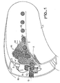
- FIG. 1 schematically represents a sectional view of a reflector 1 of common antenna for primary and secondary radars.
- This reflector 1 comprises a linear array 2 of radiating elements generating waves polarized rectilinearly or circularly (or elliptically).
- the reflector 1 is made of metallic material or dielectric 3-glass mat impregnated with epoxy-covered by a fabric 4 of glass fibers carrying gimped metallic wires 40 and 41 crossed. These wires are generally made of thin copper.
- the radiating elements are constituted by waveguides 2i, i varying from 1 to n with n representing the total number of elements of an array, comprising a polarizing device 13 which is movable in rotation around the longitudinal axis A of each guide, and is located in the plane of the reflector 1.
- This polarizing device 13 is constituted by a plane network of parallel metal blades or by several associated networks of parallel metal wires. This association of wire networks aims for better adaptation, and the spacing as the number of these associated networks allows adjustment of the width of the operating band of the radiating elements of the linear network 2.
- each waveguide must be such that it brings a short-circuit plane to the level of the reflector 1 .
- the waveguides 2i are produced in the reflector 1 from the same material as the reflector, covered in the same way by a fabric 4 of glass fibers carrying metallic wires.
- the guides are filled with dielectric 3.
- this control channel has one or more additional elements radiating towards the rear. It may be one or more waveguides 11 formed in the material of the cover 10. These additional radiating elements 11 are reduced in number and placed in the cover 10, in the plane of symmetry of the reflector 1 containing the radiating elements towards the before.
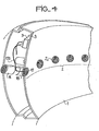
- FIG. 2 represents an alternative embodiment of a common antenna for primary and secondary radars, the elements of the radiation network of waves polarized rectilinearly or circularly or elliptically.
- the radiating elements of the network are waveguides 2i of another type-i varying from 1 to n, n being the total number of elements of the network 2-, comprising a polarizing device 14 placed inside of each guide 2i.
- This device 14 is generally constituted by a dielectric blade symmetrical with respect to the longitudinal axis A 'of each guide 2i, and movable around this axis A' so as to be able to emit waves polarized rectilinearly as circularly or elliptically, along the radiating path .
- this device can be constituted by adjustable irises making it possible to modify the opening of the guide according to the desired polarization.
- the radiating elements constituted by waveguides each comprising a polarizing device generate waves polarized rectilinearly or circularly or elliptically, according to the variable position of the polarizing device.
- the radiating elements are constituted by waveguides with fixed polarizer, they generate circularly polarized waves or else elliptically polarized waves, to the exclusion of each other.
- the elements consist of propellers 15 each placed in an excitation cavity 16 of such dimension that it brings a short-circuit plane to the level of the reflector 1.
- Each propeller is connected to the power divider 9 by 1 'through a coaxial line 150.
- the radiating elements are spirals 17 placed on the surface of the reflector and each excited by a resonant cavity 18 integrated in the same reflector and of dimensions such that they bring back a plane short circuit at the reflector. These spirals are made mechanically or deposited by photoengraving on a dielectric plate. The supply of each spiral is done via a coaxial line 170 which connects the radiating spiral 17 to the power divider system 9.
Landscapes
- Aerials With Secondary Devices (AREA)
- Variable-Direction Aerials And Aerial Arrays (AREA)
- Details Of Aerials (AREA)
- Support Of Aerials (AREA)
- Radar Systems Or Details Thereof (AREA)
- Waveguide Aerials (AREA)
Claims (8)
Priority Applications (1)
| Application Number | Priority Date | Filing Date | Title |
|---|---|---|---|
| AT81400052T ATE13111T1 (de) | 1980-01-28 | 1981-01-16 | Gemeinsame antenne fuer primaer-radar und sekundaer- radar. |
Applications Claiming Priority (2)
| Application Number | Priority Date | Filing Date | Title |
|---|---|---|---|
| FR8001760 | 1980-01-28 | ||
| FR8001760A FR2474770A2 (fr) | 1978-12-27 | 1980-01-28 | Antenne commune pour radar primaire et radar secondaire |
Publications (2)
| Publication Number | Publication Date |
|---|---|
| EP0033676A1 EP0033676A1 (de) | 1981-08-12 |
| EP0033676B1 true EP0033676B1 (de) | 1985-05-02 |
Family
ID=9237928
Family Applications (1)
| Application Number | Title | Priority Date | Filing Date |
|---|---|---|---|
| EP81400052A Expired EP0033676B1 (de) | 1980-01-28 | 1981-01-16 | Gemeinsame Antenne für Primär-Radar und Sekundär-Radar |
Country Status (6)
| Country | Link |
|---|---|
| US (1) | US4400701A (de) |
| EP (1) | EP0033676B1 (de) |
| AT (1) | ATE13111T1 (de) |
| DE (1) | DE3170227D1 (de) |
| DK (1) | DK34481A (de) |
| NO (1) | NO154070C (de) |
Families Citing this family (9)
| Publication number | Priority date | Publication date | Assignee | Title |
|---|---|---|---|---|
| FR2640431B1 (fr) * | 1988-12-08 | 1991-05-10 | Alcatel Espace | Dispositif rayonnant multifrequence |
| FR2644298A1 (fr) * | 1989-03-07 | 1990-09-14 | Malhanche Michel | Antenne destinee a la reception des signaux radio-electriques emis par les satellites geo-stationnaires |
| EP0883907B1 (de) * | 1996-02-27 | 2002-07-31 | Thomson Consumer Electronics, Inc. | Gefaltete bowtie-antenne |
| US5999137A (en) * | 1996-02-27 | 1999-12-07 | Hughes Electronics Corporation | Integrated antenna system for satellite terrestrial television reception |
| US6166703A (en) * | 1996-02-27 | 2000-12-26 | Thomson Licensing S.A. | Combination satellite and VHF/UHF receiving antenna |
| US6121936A (en) * | 1998-10-13 | 2000-09-19 | Mcdonnell Douglas Corporation | Conformable, integrated antenna structure providing multiple radiating apertures |
| US7126553B1 (en) * | 2003-10-02 | 2006-10-24 | The United States Of America As Represented By The Administrator Of The National Aeronautics And Space Administration | Deployable antenna |
| DE102010034073A1 (de) * | 2010-08-12 | 2012-02-16 | Conti Temic Microelectronic Gmbh | Vorrichtung zur Montage einer Sensor-Baugruppe, insbesondere eines Radarsensors |
| CN119814056B (zh) * | 2025-03-17 | 2025-05-23 | 烟台初心航空科技有限公司 | 二次测风探空雷达探空仪通信装置 |
Family Cites Families (6)
| Publication number | Priority date | Publication date | Assignee | Title |
|---|---|---|---|---|
| FR1094892A (fr) * | 1953-10-16 | 1955-05-25 | Thomson Houston Comp Francaise | Perfectionnement aux antennes pour ondes ultra-courtes |
| US2895127A (en) * | 1954-07-20 | 1959-07-14 | Rca Corp | Directive diplex antenna |
| US3445850A (en) * | 1965-11-08 | 1969-05-20 | Canoga Electronics Corp | Dual frequency antenna employing parabolic reflector |
| NL6704219A (de) * | 1967-03-22 | 1968-09-23 | ||
| FR1540954A (fr) * | 1967-05-16 | 1968-10-04 | Csf | Perfectionnement aux polariseurs transmetteurs |
| FR2445629A1 (fr) * | 1978-12-27 | 1980-07-25 | Thomson Csf | Antenne commune pour radar primaire et radar secondaire |
-
1981
- 1981-01-16 AT AT81400052T patent/ATE13111T1/de not_active IP Right Cessation
- 1981-01-16 DE DE8181400052T patent/DE3170227D1/de not_active Expired
- 1981-01-16 EP EP81400052A patent/EP0033676B1/de not_active Expired
- 1981-01-23 US US06/227,770 patent/US4400701A/en not_active Expired - Fee Related
- 1981-01-26 DK DK34481A patent/DK34481A/da not_active Application Discontinuation
- 1981-01-27 NO NO810277A patent/NO154070C/no unknown
Non-Patent Citations (1)
| Title |
|---|
| Antenna Engineering Handbook-Henry Jasik, Editor, MacGraw Hill, 1961 Ch. 17 p. 17-2, 17-3, 17-17,17-18, 17-20, 17-21 * |
Also Published As
| Publication number | Publication date |
|---|---|
| DE3170227D1 (en) | 1985-06-05 |
| DK34481A (da) | 1981-07-29 |
| NO154070C (no) | 1986-07-09 |
| US4400701A (en) | 1983-08-23 |
| NO810277L (no) | 1981-07-29 |
| ATE13111T1 (de) | 1985-05-15 |
| EP0033676A1 (de) | 1981-08-12 |
| NO154070B (no) | 1986-04-01 |
Similar Documents
| Publication | Publication Date | Title |
|---|---|---|
| EP1145379B1 (de) | Antenne mit einer filtermaterialanordnung | |
| EP1568104B1 (de) | Mehrfachstrahlantenne mit photonischem bandlückenmaterial | |
| EP0013240B1 (de) | Gemeinsame Antenne für Primär- und Sekundärradar | |
| FR2647269A1 (fr) | Systeme d'antenne a fentes | |
| FR2930079A1 (fr) | Capteur de rayonnement, notamment pour radar | |
| FR2655778A1 (fr) | Antenne iff aeroportee a diagrammes multiples commutables. | |
| EP0147325B1 (de) | Antenne mit zwei gekreuzten parabolisch-cylindrischen Reflektoren und Verfahren zur Herstellung derselben | |
| FR2491686A1 (fr) | Antenne directive de radar multimode a alimentation double | |
| EP3435480B1 (de) | Antenne mit integrierten verzögerungslinsen im innern eines verteilers auf der basis von wellenleiterteilern mit parallelen platten | |
| EP0033676A1 (de) | Gemeinsame Antenne für Primär-Radar und Sekundär-Radar | |
| EP1554777B1 (de) | Mehrfachstrahlantenne mit photonischem bandlückenmaterial | |
| EP0045254B1 (de) | Kompakter Mikrowellenerreger für zwei Frequenzbereiche | |
| FR2687013A1 (fr) | Aerien pour radar. | |
| WO1999027611A1 (en) | Photonically controlled antenna array | |
| EP0439970A1 (de) | Geschlitzter Hohlleiterstrahler mit quer verlaufenden Schlitzen, die von gedruckten, leitenden Mustern erregt werden | |
| FR2474770A2 (fr) | Antenne commune pour radar primaire et radar secondaire | |
| EP0456579A1 (de) | Flache, orientierbare Antenne, arbeitend im Mikrowellenbereich | |
| FR2490025A1 (fr) | Antenne du type cornet monomode ou multimode comprenant au moins deux voies radar et fonctionnant dans le domaine des hyperfrequences | |
| FR2560446A1 (fr) | Repartiteur de puissance pour antenne a faisceaux multiples a elements sources partages | |
| EP0551780B1 (de) | Phasengesteuerte Gruppenantenne mit Reflektor | |
| FR2470457A1 (fr) | Antenne a reseau a fentes avec distribution d'amplitude dans une petite ouverture circulaire | |
| EP0088681B1 (de) | Doppelreflektorantenne mit eingebautem Polarisationswandler | |
| EP0028185A1 (de) | Radarantenne mit Elementen, die ein pseudo-omnidirektionelles Diagramm abstrahlen | |
| FR2943466A1 (fr) | Element rayonnant a bipolarisation | |
| FR2632780A1 (fr) | Radome d'antenne eliminant l'effet d'une perturbation du type couche de glace |
Legal Events
| Date | Code | Title | Description |
|---|---|---|---|
| PUAI | Public reference made under article 153(3) epc to a published international application that has entered the european phase |
Free format text: ORIGINAL CODE: 0009012 |
|
| AK | Designated contracting states |
Designated state(s): AT BE CH DE GB IT LI LU NL SE |
|
| 17P | Request for examination filed |
Effective date: 19810817 |
|
| ITF | It: translation for a ep patent filed | ||
| GRAA | (expected) grant |
Free format text: ORIGINAL CODE: 0009210 |
|
| AK | Designated contracting states |
Designated state(s): AT BE CH DE GB IT LI LU NL SE |
|
| REF | Corresponds to: |
Ref document number: 13111 Country of ref document: AT Date of ref document: 19850515 Kind code of ref document: T |
|
| REF | Corresponds to: |
Ref document number: 3170227 Country of ref document: DE Date of ref document: 19850605 |
|
| PGFP | Annual fee paid to national office [announced via postgrant information from national office to epo] |
Ref country code: LU Payment date: 19860116 Year of fee payment: 6 |
|
| PG25 | Lapsed in a contracting state [announced via postgrant information from national office to epo] |
Ref country code: LU Free format text: LAPSE BECAUSE OF NON-PAYMENT OF DUE FEES Effective date: 19860131 |
|
| PLBE | No opposition filed within time limit |
Free format text: ORIGINAL CODE: 0009261 |
|
| STAA | Information on the status of an ep patent application or granted ep patent |
Free format text: STATUS: NO OPPOSITION FILED WITHIN TIME LIMIT |
|
| 26N | No opposition filed | ||
| PGFP | Annual fee paid to national office [announced via postgrant information from national office to epo] |
Ref country code: AT Payment date: 19870130 Year of fee payment: 7 |
|
| PGFP | Annual fee paid to national office [announced via postgrant information from national office to epo] |
Ref country code: NL Payment date: 19870131 Year of fee payment: 7 |
|
| PG25 | Lapsed in a contracting state [announced via postgrant information from national office to epo] |
Ref country code: AT Effective date: 19880116 |
|
| PG25 | Lapsed in a contracting state [announced via postgrant information from national office to epo] |
Ref country code: SE Effective date: 19880117 |
|
| PG25 | Lapsed in a contracting state [announced via postgrant information from national office to epo] |
Ref country code: LI Effective date: 19880131 Ref country code: CH Effective date: 19880131 |
|
| BERE | Be: lapsed |
Owner name: THOMSON-CSF Effective date: 19880131 |
|
| PG25 | Lapsed in a contracting state [announced via postgrant information from national office to epo] |
Ref country code: NL Effective date: 19880801 |
|
| NLV4 | Nl: lapsed or anulled due to non-payment of the annual fee | ||
| GBPC | Gb: european patent ceased through non-payment of renewal fee | ||
| REG | Reference to a national code |
Ref country code: CH Ref legal event code: PL |
|
| PG25 | Lapsed in a contracting state [announced via postgrant information from national office to epo] |
Ref country code: DE Effective date: 19881001 |
|
| PG25 | Lapsed in a contracting state [announced via postgrant information from national office to epo] |
Ref country code: GB Free format text: LAPSE BECAUSE OF NON-PAYMENT OF DUE FEES Effective date: 19881118 |
|
| PG25 | Lapsed in a contracting state [announced via postgrant information from national office to epo] |
Ref country code: BE Effective date: 19890131 |
|
| EUG | Se: european patent has lapsed |
Ref document number: 81400052.7 Effective date: 19880913 |