EP0034066A2 - Appareil d'impression à superposition de formulaires - Google Patents
Appareil d'impression à superposition de formulaires Download PDFInfo
- Publication number
- EP0034066A2 EP0034066A2 EP81300541A EP81300541A EP0034066A2 EP 0034066 A2 EP0034066 A2 EP 0034066A2 EP 81300541 A EP81300541 A EP 81300541A EP 81300541 A EP81300541 A EP 81300541A EP 0034066 A2 EP0034066 A2 EP 0034066A2
- Authority
- EP
- European Patent Office
- Prior art keywords
- drum
- forms
- signal
- page
- alignment
- Prior art date
- Legal status (The legal status is an assumption and is not a legal conclusion. Google has not performed a legal analysis and makes no representation as to the accuracy of the status listed.)
- Withdrawn
Links
Images

Classifications
-
- G—PHYSICS
- G03—PHOTOGRAPHY; CINEMATOGRAPHY; ANALOGOUS TECHNIQUES USING WAVES OTHER THAN OPTICAL WAVES; ELECTROGRAPHY; HOLOGRAPHY
- G03B—APPARATUS OR ARRANGEMENTS FOR TAKING PHOTOGRAPHS OR FOR PROJECTING OR VIEWING THEM; APPARATUS OR ARRANGEMENTS EMPLOYING ANALOGOUS TECHNIQUES USING WAVES OTHER THAN OPTICAL WAVES; ACCESSORIES THEREFOR
- G03B27/00—Photographic printing apparatus
- G03B27/32—Projection printing apparatus, e.g. enlarger, copying camera
- G03B27/52—Details
- G03B27/62—Holders for the original
- G03B27/6207—Holders for the original in copying cameras
- G03B27/6242—Masks; Overlays; Transparent carriers
-
- G—PHYSICS
- G06—COMPUTING OR CALCULATING; COUNTING
- G06K—GRAPHICAL DATA READING; PRESENTATION OF DATA; RECORD CARRIERS; HANDLING RECORD CARRIERS
- G06K15/00—Arrangements for producing a permanent visual presentation of the output data, e.g. computer output printers
- G06K15/02—Arrangements for producing a permanent visual presentation of the output data, e.g. computer output printers using printers
- G06K15/12—Arrangements for producing a permanent visual presentation of the output data, e.g. computer output printers using printers by photographic printing, e.g. by laser printers
- G06K15/1276—Arrangements for producing a permanent visual presentation of the output data, e.g. computer output printers using printers by photographic printing, e.g. by laser printers adding two or more images, e.g. texturing, shading, form overlay
-
- H—ELECTRICITY
- H04—ELECTRIC COMMUNICATION TECHNIQUE
- H04N—PICTORIAL COMMUNICATION, e.g. TELEVISION
- H04N1/00—Scanning, transmission or reproduction of documents or the like, e.g. facsimile transmission; Details thereof
- H04N1/387—Composing, repositioning or otherwise geometrically modifying originals
- H04N1/3872—Repositioning or masking
Definitions
- This invention relates to a printer having provision for forms overlay.
- the invention will be described with particular reference to laser-xerographic printers, although it is also applicable to printers of other types.
- Laser-xerographic printers comprise one type of non-impact printer well known in the art (see U.S. patent 3,659,936 and 3,698,006). They utilize a modulated beam of laser light which is caused to sweep periodically across a photoconducting drum. The information represented by the modulated light is thereby temporarily stored as electrostatic charges on the surface of the drum. In some laser-xerographic printers the electrostatic image is developed with a toner and the toned image is then transferred to paper to form a permanent record.
- Mechanical interconnections can be made by mounting the forms drum above the printer, for example, with the axis of the forms drum parallel to the axis of the photoconducting drum, and with belt and pulleys connecting the ends of the two drums so that when one drum turns the other also turns.
- the forms drum rotates, light transmitted through the graphic forms negative causes a light image of a linear portion of the graphic form pattern to be directed onto that linear portion of the photoconducting drum being swept by the laser at that time.
- a system of lenses and mirrors directs the light images from the forms drum to the photoconducting drum.
- the forms drum may be mounted above the printer, and the drive belt coupling the two drums passed through an opening in the top of the printer and round an end of the photoconducting drum.
- an indicator means must be provided on the forms drum.
- this includes a pair of protrusions on the forms drum lying along a line parallel to the axis of the drum.
- Graphics forms negatives are made with two spaced-apart alignment holes which receive the two protrusions on the forms drum on the graphic forms negative when it is placed on the drum. This method of alignment requires that the holes be placed accurately on the graphic forms negative and that the initial rotational position of the forms drum have a predetermined relationship with the initial position of the photoconducting drum. If the holes in the graphic forms master are not properly positioned from one graphic forms master to the next, or, if the rotational relationship of the two drums is disturbed, the form will not be properly aligned with the data.
- An alternative known means of providing synchronized rotation between the forms drum and photoconducting drum requires the use of synchronous motors for both drums.
- the two synchronous motors rotate continuously in phase with one another at the same rate.
- the synchronous motors may be connected to the drums through gearing in order to compensate for differences in diameter between the two drums.
- An alignment mark located on the graphic form is detected by a detector once every revolution of the forms drum, and the detector transmits a top-of-forms signal to the printer which starts a page of printing.
- the graphic forms image is aligned with the data image from the printer on the photoconducting drum.
- the printer must wait for the signal from the forms drum before printing can be initiated.
- the photoconducting drum is fabricated with a seam running along the surface of the drum parallel to the axis of the drum. No imaging of data can take place along the seam or a small region surrounding the seam.
- the invention provides a graphic forms overlay feature which does not require mechanical coupling between, or synchronous motor drives for, the forms drum and the movable light sensitive medium. This allows of easier assembly of the forms overlay apparatus. It also facilitates retro-fitting of the forms overlay system.
- the invention also provides automatic alignment of the drums, without interfering with printing by the printer. Any adjustment necessary to accommodate variations in the graphic forms negative may be made by adjusting the parameters of the logic circuitry.
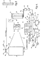
- FIG. 1 is a diagrammatic remediation of a graphic forms overlay apparatus designated generally 10, and a laser-xerographic printer.
- a laser light source 11 transmits a beam of light through an acoustic-optical modulator 13 which, in the preferred embodiment, comprises a slab of glass with a piezo-electric transducer attached thereto.
- Digital signals generated by the character generator within the printer controller 14 and representing information data to be printed modulate an RF generator 15.
- the path of a portion of a laser beam through the modulator 13 is deflected slightly from the normal path travelled through the slab when no RF signal is present.
- the beam of light emerges from the modulator 13 and passes through a lens 12 which narrows the cross-section of the beam of light.
- the beam continues on to a rotating polygonal mirror. 19..
- the planar surfaces of the rotating mirror 19 sweeps the laser beam across a photoconducting drum 17.
- the beam is switched by the piezo-electric modulator 17, so that when an RF signal is present the laser beam will impinge upon the drum, otherwise it will not.
- the photoconducting drum is cylindrical and stores data as a pattern of electrostatic charges on its surface, created in response to illumination by the laser beam.
- the laser beam moves from left to right along the surface of the drum parallel to its axis. As the drum rotates, the laser beam sweeps out periodic parallel paths on the drum, printing a whole page of data thereon.
- the overlay apparatus comprises a hollow cylindrical forms drum 16 rotated by a motor 18 coupled to it by a belt and pulley arrangement 20.
- the surface of the forms drum 16 is transparent, and a light source such as a cylindrical fluorescent light element 30 in Figure 3 is mounted inside its drum 1.
- the fluorescent tube 30 does not rotate with the drum 16.
- a negative of a graphic form, such as the negative 32 in Figure 2 is shown mounted on the surface of the forms drum 16 in Figure 1.
- Figure 2 is a representation of a negative.
- the region surrounding both the transparent portion 68 and the forms pattern to be printed is opaque while the transparent portion 68 and forms pattern are transparent.
- the surface of the fluorescent tube 30 is opaque except for a linear portion 36, which illuminates a strip of the negative of the graphic form 32 as the forms drum rotates.
- Light from this strip travels along the path 22 in Figure 1 and is first reflected from a mirror 24 along the path 25 through lenses 26 and 27 to the mirror 28.
- the mirror which is parallel to the mirror 24 reflects the light along the path 29 to the photoconducting drum 17.
- the arrangement of the drums 17 and 16 and the optical components comprising the mirrors 24 and 28 and the lenses 26 and 27 is such that the linear image produced on the photoconducting drum 17 coincides with the linear sweep of the laser beam.
- the cross section of the linear beam of light is approximately one half inch (12mm) high as it impinges on the drum 17.
- a fluorescent tube with a totally transparent surface may also be used. However, the light transmitted will be spread over the entire negative, lessening the concentration of light captured by the optical arrangement for reflection on to the photoconducting drum 17.
- FIG. 4 is a schematic diagram of the graphic forms overlay apparatus 10 including the logic circuitry means designated generally 50.
- the laser beam sweeps across the photoconducting drum 17 it sweeps from the dashed line 52 to the dashed line 54.
- Each sweep of the laser beam first impinges on the photodetector 56 to the left of the photoconducting drum 17, and this provides a periodic start-of-sweep signal.
- a drive casting 58 at one end of the drum 17, 58 ends in a light reflecting end portion 60 with a darkened section 62.
- Light from a light source 64 is reflected from the end portion 60 and is detected by a photodetector 66.
- the darkened section 62 is positioned so that the interruption of the signal from the photodetector 60 indicates the top of the next page of data to be printed by the printer. If more than one page of data is to be imaged on the photoconducting drum, then a corresponding number of darkened sections 62 are positioned on the end portion 60 to provide top-of-page signals.
- the negative 32 includes a small transparent portion 68 which, in one position of the forms drum, allows light to strike a photodetector 70, providing an alignment signal for automatic alignment of the initial position of the forms drum 16 with the top-of-page position of the photoconducting drum 17.
- the transparent portion must be in a left or right margin of the negative, i.e., outside the area of the negative where the graphics forms pattern is located, with the photodetector 70 correspondingly positioned, so that light transmitted through the forms pattern does not illuminate the photodetector, causing a false alignment signal to be generated.
- the forms drum must be started in time with the top of page signals generated by rotation of the photoconducting drum 17. Rotation of the photoconducting drum 17 is free running and imaging of a page of data on the photoconducting drum is initiated by a top of page signal. Rotation of the forms drum 16 is aligned with the top of page signals by operation of the logic circuitry means 50 in cooperation with the top of page and alignment signals.
- the drive motor 18 is preferably a stepping motor, for example Superior Electric Motor, model M061-F002, which makes a complete revolution in 200 steps or equivalently provides 1.8 degrees of rotation per step.
- the drive signals for the motor may be generated by a motor interface board 80 Model No. STM 103 also made by Superior Electric. Designed to receive TTL-like digital input signals, the board provides a drive current which advances in phase each time an input signal is received. Continuous changes in drive current phase cause the motor to rotate in -response to the above-mentioned input signals.
- Periodic digital signals are provided by clock-counter circuitry designated generally 81 of the logic circuitry means 50.
- the output of a crystal controlled master clock 82 is first divided by sixteen by a counter 83, which may be a type 74161 TTL device. This provides periodic basic clocking signals over line 84 for driving the remaining counter circuitry comprising type 74161 counters 85, 86 and 87.
- the counters 85 and 86 can be loaded externally with any of a range of pre-set counts by means of switching means 88. In the preferred embodiment, a fixed pre-set count is loaded into counter 87.
- the clock-counter circuitry 81 provides a means for compensating for variations in the diameter of the forms drum 16 or in the length of the negative 32, which variations would affect proper rotational synchronism between the drums 16 and 17.
- the periodic digital signals to AND gate 89 should be generated by clock counter circuitry 81.
- periodic start- . of-sweep signals from the photodetector 56 can be connected directly to the AND gate 89 to serve as the digital signals for the interface board 80.
- Other periodic signals or derivations thereof related to the sweeping rate of the laser of the photoconducting drum could also be utilized to provide digital signals to the AND gate 89.
- the clock-counter circuitry 81 is utilized to provide an adjustment means for compensating for variations in forms drum diameter and errors in negative fabrication, etc.
- Rotation of the stepping motor 83 begins when a top-of-page signal from the photodetector 66 sets the D flip flop 90 over the line 92.
- the output of the D flip flop 90 is connected to the AND gate 89 via the line 94.
- a high signal to the AND gate 89 from the flip flop 90 gates the digital signals on the line 91 to the stepping motor 18.
- the output of flip flop 90 will be set to the high state when the set input S over the line 92 is low.
- the current from the photodetector 66 stops when its darkened section 62 interrupts the reflected light from the end portion 60.
- the output from the photodetector 66 is transmitted to the negative side of a differential amplifier 98, which is an LM 3900 device.
- differential amplifier 98 When the current to the negative side stops, then differential amplifier 98 provides a high signal output. This high signal is inverted by an inverter 96 to provide a low signal over the line 92 which sets the flip flop 90. Then, periodic drive signals can pass through the AND gate 89 to the motor 18 via the interface board 80 as long as the output on line 94 is high.
- the amplifier 104 supplies a signal to the single shot multi-vibrator 100, which is a 74LS221 TTL device.
- a low signal output pulse from the multivibrator 100 provides a delayed clocking input to a D flip flop 90.
- the D flip flop 90 has a low signal on the D line and this is transferred to the output of the flip flop 90 on the positive going or trailing edge of the low multi-vibrator output pulse.
- This low signal on the line 94 blocks its AND gate 89 from passing drive signals to the stepping motor 18.
- the output pulse width of the multi-vibrator 100 can be varied externally with suitable selection of resistance and capacitance connected to selected pin connections of the multi-vibrator 100. This in turn varies the time at which the trailing edge of the multi-vibrator output pulse is inputted to the D flip flop 90. Hence, the time interval between the arrival of the signal from its photodetector 70 to the multi-vibrator 100 and the transmitting of a low signal from the D flip flop 90 on the line 94 can be varied. This allows the forms drum 16 to rotate several more steps to bring it into the correct position for the start of the next page.
- two pages of data are imaged on the photoconducting drum 17 for each revolution of the drum 17, while the forms drum 16 rotates one revolution for each page imaged on the drum 17.
- the circumference of the forms drum 16 is less than the distance from the top of one page of data to the top of the next page of data on the photoconducting drum 17.
- Adjustment of the parameters of multi-vibrator 100 provides a means for correcting an error in locating the transparent portion 68 on the negative.
Landscapes
- Physics & Mathematics (AREA)
- Engineering & Computer Science (AREA)
- General Physics & Mathematics (AREA)
- Multimedia (AREA)
- General Engineering & Computer Science (AREA)
- Theoretical Computer Science (AREA)
- Optics & Photonics (AREA)
- Signal Processing (AREA)
- Combination Of More Than One Step In Electrophotography (AREA)
- Facsimile Scanning Arrangements (AREA)
- Dot-Matrix Printers And Others (AREA)
- Laser Beam Printer (AREA)
- Optical Recording Or Reproduction (AREA)
- Control Or Security For Electrophotography (AREA)
Applications Claiming Priority (2)
| Application Number | Priority Date | Filing Date | Title |
|---|---|---|---|
| US06/120,592 US4302096A (en) | 1980-02-11 | 1980-02-11 | Graphic forms overlay apparatus |
| US120592 | 1980-02-11 |
Publications (2)
| Publication Number | Publication Date |
|---|---|
| EP0034066A2 true EP0034066A2 (fr) | 1981-08-19 |
| EP0034066A3 EP0034066A3 (fr) | 1982-03-24 |
Family
ID=22391295
Family Applications (1)
| Application Number | Title | Priority Date | Filing Date |
|---|---|---|---|
| EP81300541A Withdrawn EP0034066A3 (fr) | 1980-02-11 | 1981-02-10 | Appareil d'impression à superposition de formulaires |
Country Status (4)
| Country | Link |
|---|---|
| US (1) | US4302096A (fr) |
| EP (1) | EP0034066A3 (fr) |
| JP (1) | JPS56120256U (fr) |
| CA (1) | CA1152144A (fr) |
Cited By (1)
| Publication number | Priority date | Publication date | Assignee | Title |
|---|---|---|---|---|
| EP0107184B1 (fr) * | 1982-10-22 | 1987-01-14 | Hitachi, Ltd. | Copieur électrophotographique |
Families Citing this family (4)
| Publication number | Priority date | Publication date | Assignee | Title |
|---|---|---|---|---|
| US4493549A (en) * | 1980-04-11 | 1985-01-15 | Coulter Systems Corp. | Optical system for imaging an electrophotographic member |
| NL8600888A (nl) * | 1986-04-09 | 1987-11-02 | Oce Nederland Bv | Inrichting en werkwijze voor het afdrukken van informatie. |
| US4835570A (en) * | 1988-04-20 | 1989-05-30 | Xerox Corporation | Apparatus for printing fixed and variable indicia |
| US8339573B2 (en) * | 2009-05-27 | 2012-12-25 | 3M Innovative Properties Company | Method and apparatus for photoimaging a substrate |
Family Cites Families (11)
| Publication number | Priority date | Publication date | Assignee | Title |
|---|---|---|---|---|
| US3598489A (en) * | 1969-01-02 | 1971-08-10 | Spaco Inc | Projection system |
| US3698006A (en) * | 1969-05-29 | 1972-10-10 | Energy Conversion Devices Inc | High speed printer of multiple copies for output information |
| US3659936A (en) * | 1970-01-07 | 1972-05-02 | Energy Conversion Devices Inc | Apparatus for electrostatic printing |
| US3922485A (en) * | 1972-11-27 | 1975-11-25 | Xerox Corp | Flying spot scanner with scan detection |
| US3864697A (en) * | 1973-07-25 | 1975-02-04 | Eastman Kodak Co | Non-impact printer |
| US4122462A (en) * | 1974-09-11 | 1978-10-24 | Canon Kabushiki Kaisha | Image information recording apparatus |
| JPS6111018B2 (fr) * | 1974-10-18 | 1986-04-01 | Fuji Photo Film Co Ltd | |
| US3998544A (en) * | 1975-06-13 | 1976-12-21 | Terminal Data Corporation | Synchronous auxiliary camera projector |
| US4082443A (en) * | 1976-01-08 | 1978-04-04 | Xerox Corporation | System for superposition of color separation images |
| US4190352A (en) * | 1977-06-30 | 1980-02-26 | Bell Telephone Laboratories, Incorporated | Method and apparatus for continuously patterning a photosensitive tape |
| JPS5849859B2 (ja) * | 1979-04-20 | 1983-11-07 | 富士通株式会社 | 書式印刷装置 |
-
1980
- 1980-02-11 US US06/120,592 patent/US4302096A/en not_active Expired - Lifetime
- 1980-08-14 CA CA000358258A patent/CA1152144A/fr not_active Expired
-
1981
- 1981-02-09 JP JP1981016097U patent/JPS56120256U/ja active Pending
- 1981-02-10 EP EP81300541A patent/EP0034066A3/fr not_active Withdrawn
Cited By (1)
| Publication number | Priority date | Publication date | Assignee | Title |
|---|---|---|---|---|
| EP0107184B1 (fr) * | 1982-10-22 | 1987-01-14 | Hitachi, Ltd. | Copieur électrophotographique |
Also Published As
| Publication number | Publication date |
|---|---|
| CA1152144A (fr) | 1983-08-16 |
| JPS56120256U (fr) | 1981-09-12 |
| EP0034066A3 (fr) | 1982-03-24 |
| US4302096A (en) | 1981-11-24 |
Similar Documents
| Publication | Publication Date | Title |
|---|---|---|
| CA1075758A (fr) | Appareil electrophotographique a deux modes, muni d'un faisceau d'impression a deux fonctions | |
| KR100310713B1 (ko) | 위치정렬제어를갖는정전기록단일-패스다단프린터 | |
| US5381165A (en) | Raster output scanner with process direction registration | |
| JPH07102713B2 (ja) | 画素位置を修正する方法 | |
| EP0124641A1 (fr) | Collecteur d'énergie radiant pour l'utilisation dans un système de grille optique | |
| US4216378A (en) | Optical scanner | |
| EP0034066A2 (fr) | Appareil d'impression à superposition de formulaires | |
| US4060322A (en) | Image information handling device | |
| JPH1086446A (ja) | 画像形成システム | |
| US5821978A (en) | Image forming apparatus for forming an image in use with a plurality of laser beam scanners | |
| JPH047630B2 (fr) | ||
| JPH10190985A (ja) | カスケード走査光学系を備えた記録装置 | |
| JPH09118042A (ja) | 画像形成システム | |
| EP0968834A1 (fr) | Méthode et appareil pour gérer l'operation d'une imprimante | |
| JPS59198076A (ja) | 画像形成装置 | |
| JP2965527B2 (ja) | 画像形成装置 | |
| KR100265731B1 (ko) | 인쇄기의 광주사 시스템 | |
| JPS63210910A (ja) | 画像形成装置 | |
| JPH0671948A (ja) | カラー画像形成装置 | |
| JPS6220839Y2 (fr) | ||
| JP3443242B2 (ja) | 光走査装置及び画像形成装置 | |
| JPH0580191B2 (fr) | ||
| JP2836559B2 (ja) | 電子写真式カラープリンタ | |
| US4317004A (en) | Imaging and scanning system | |
| JPH01154071A (ja) | 画像位置制御装置 |
Legal Events
| Date | Code | Title | Description |
|---|---|---|---|
| PUAI | Public reference made under article 153(3) epc to a published international application that has entered the european phase |
Free format text: ORIGINAL CODE: 0009012 |
|
| AK | Designated contracting states |
Designated state(s): DE FR GB IT SE |
|
| PUAL | Search report despatched |
Free format text: ORIGINAL CODE: 0009013 |
|
| AK | Designated contracting states |
Designated state(s): DE FR GB IT SE |
|
| RHK1 | Main classification (correction) |
Ipc: G03G 15/052 |
|
| STAA | Information on the status of an ep patent application or granted ep patent |
Free format text: STATUS: THE APPLICATION IS DEEMED TO BE WITHDRAWN |
|
| 18D | Application deemed to be withdrawn |
Effective date: 19830228 |
|
| RIN1 | Information on inventor provided before grant (corrected) |
Inventor name: CURLEY, JOSEPH MICHAEL |