EP0034310B1 - Circuit pour obtenir une impulsion de retour de lignes dans un récepteur de télévision - Google Patents
Circuit pour obtenir une impulsion de retour de lignes dans un récepteur de télévision Download PDFInfo
- Publication number
- EP0034310B1 EP0034310B1 EP81100838A EP81100838A EP0034310B1 EP 0034310 B1 EP0034310 B1 EP 0034310B1 EP 81100838 A EP81100838 A EP 81100838A EP 81100838 A EP81100838 A EP 81100838A EP 0034310 B1 EP0034310 B1 EP 0034310B1
- Authority
- EP
- European Patent Office
- Prior art keywords
- coil
- amplitude
- primary winding
- line
- fly
- Prior art date
- Legal status (The legal status is an assumption and is not a legal conclusion. Google has not performed a legal analysis and makes no representation as to the accuracy of the status listed.)
- Expired
Links
Images
Classifications
-
- H—ELECTRICITY
- H04—ELECTRIC COMMUNICATION TECHNIQUE
- H04N—PICTORIAL COMMUNICATION, e.g. TELEVISION
- H04N3/00—Scanning details of television systems; Combination thereof with generation of supply voltages
- H04N3/10—Scanning details of television systems; Combination thereof with generation of supply voltages by means not exclusively optical-mechanical
- H04N3/16—Scanning details of television systems; Combination thereof with generation of supply voltages by means not exclusively optical-mechanical by deflecting electron beam in cathode-ray tube, e.g. scanning corrections
- H04N3/22—Circuits for controlling dimensions, shape or centering of picture on screen
- H04N3/223—Controlling dimensions
-
- H—ELECTRICITY
- H04—ELECTRIC COMMUNICATION TECHNIQUE
- H04N—PICTORIAL COMMUNICATION, e.g. TELEVISION
- H04N5/00—Details of television systems
- H04N5/04—Synchronising
- H04N5/12—Devices in which the synchronising signals are only operative if a phase difference occurs between synchronising and synchronised scanning devices, e.g. flywheel synchronising
Definitions
- line return pulses are known to be required for various purposes, e.g. B. for the phase comparison for the line synchronization, for the control of an interference protection circuit when the line output stage is overloaded, for the keyed fading control, for the blanking or blanking of the color synchronizing signal, for clamping the video signal and the like.
- the invention is based on the object of deriving a return pulse from the path of the line deflection current, the amplitude of which is largely independent of the respectively set value of the line deflection current.
- the invention is based on the following knowledge. If one forms the primary winding of the above-mentioned transformer in the deflection current path to the amplitude coil as a pure air coil with relatively little coupling, then initially the amplitude of the return pulse taken from the secondary winding would still be dependent on that of the line deflection current.
- the spatial distance between the amplitude coil and the primary winding can be chosen so that this dependency can be compensated for by the core screwed into the amplitude coil. This can be explained in such a way that the core that is rotated into the amplitude coil and approaches the primary winding also increases the coupling between the amplitude coil and the primary winding to the desired extent when the inductance of the amplitude coil increases.
- the core does not penetrate the primary winding even in its screwed-in end position.
- a major advantage is that a single bobbin can remove both the amplitude coil and the transformer for decoupling the return pulse.
- the transformer for decoupling the return pulse does not form an additional component.
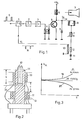
- Fig. 1 shows the stripped from the video signal Line synchronizing pulses S, the phase comparison stage 1, the line oscillator 2, the T: stage 3, the driver transformer 4, the cell output stage transistor 5, the primary winding 6 of the line transformer, the picture tube 7, the line deflection coils 8, the flyback capacitor 9 , the variable amplitude coil 10 used to adjust the image width and the tangent capacitor 11.
- the primary winding 12 is switched on, which is coupled as an air coil to the secondary winding 13. This supplies the line return pulse 14 for the phase comparison stage 1 via the line 15.
- the amplitude coil 10, on the one hand, and the two windings 12, 13, on the other hand, are arranged on the coil former 16 at a distance a axially offset from one another.
- the primary winding 12 is above the secondary winding 13.
- the distance a is now such that when the amplitude of the line deflection current i A and thus the image width are adjusted by means of the amplitude coil 10, the amplitude of the return pulse 14 is practical remains constant.
- FIG. 3 shows the amplitude U 14 of the return pulse 14 as a function of the penetration depth b of the core 17 into the coil body 16.
- the inductance of the coil 10 is increased, the amplitude of the deflection current i A and thus also of the return pulse 14 in undesirably downsized. This is indicated by curve 21 and applies in the event that the distance a is chosen too large.
- the core 17 is turned upwards out of the coil carrier 16.
- the inductance of the coil 10 could also be reduced by rotating the core 17 downward out of the area of the coil 10.
- the coil carrier is designed so that the core 17 can only be screwed in up to point 20.
- the core 17 can only be screwed in up to point 20.
- e.g. B. ends the threaded hole in the core and the bobbin solid.
- Another possibility is to no longer provide any thread in the area of the coil carrier 16 below the point 20 in the bore.
- the following number of turns was chosen:
Landscapes
- Engineering & Computer Science (AREA)
- Multimedia (AREA)
- Signal Processing (AREA)
- Details Of Television Scanning (AREA)
Claims (5)
Priority Applications (1)
| Application Number | Priority Date | Filing Date | Title |
|---|---|---|---|
| AT81100838T ATE4479T1 (de) | 1980-02-16 | 1981-02-06 | Schaltung zur gewinnung eines zeilenruecklaufimpulses in einem fernsehempfaenger. |
Applications Claiming Priority (2)
| Application Number | Priority Date | Filing Date | Title |
|---|---|---|---|
| DE3005826A DE3005826C2 (de) | 1980-02-16 | 1980-02-16 | Schaltung zur Gewinnung eines Zeilenrücklaufimpulses in einem Fernsehempfänger |
| DE3005826 | 1980-02-16 |
Publications (2)
| Publication Number | Publication Date |
|---|---|
| EP0034310A1 EP0034310A1 (fr) | 1981-08-26 |
| EP0034310B1 true EP0034310B1 (fr) | 1983-08-17 |
Family
ID=6094775
Family Applications (1)
| Application Number | Title | Priority Date | Filing Date |
|---|---|---|---|
| EP81100838A Expired EP0034310B1 (fr) | 1980-02-16 | 1981-02-06 | Circuit pour obtenir une impulsion de retour de lignes dans un récepteur de télévision |
Country Status (3)
| Country | Link |
|---|---|
| EP (1) | EP0034310B1 (fr) |
| AT (1) | ATE4479T1 (fr) |
| DE (2) | DE3005826C2 (fr) |
Cited By (1)
| Publication number | Priority date | Publication date | Assignee | Title |
|---|---|---|---|---|
| DE4137656A1 (de) * | 1991-11-15 | 1993-05-19 | Thomson Brandt Gmbh | Zeilenablenkschaltung fuer einen fernsehempfaenger |
Families Citing this family (1)
| Publication number | Priority date | Publication date | Assignee | Title |
|---|---|---|---|---|
| DE3618953A1 (de) * | 1986-06-05 | 1987-12-10 | Electronic Werke Deutschland | Amplitudenspule fuer die zeilenendstufe eines fernsehempfaengers |
Family Cites Families (3)
| Publication number | Priority date | Publication date | Assignee | Title |
|---|---|---|---|---|
| DE1252732B (de) * | 1964-10-02 | 1967-10-26 | Blaupunkt-Werke GmbH, HiIdesheim | Schaltungsanordnung zur Zeilensynchromsation in einem Fernsehempfanger |
| US3715499A (en) * | 1970-12-03 | 1973-02-06 | Rca Corp | Dual mode automatic frequency controlled oscillator system |
| NL158342B (nl) * | 1971-03-16 | 1978-10-16 | Philips Nv | Televisie-ontvanger met een beeldregelsynchroniseerschakeling en een beeldregelsynchroniseerschakeling voor deze ontvanger. |
-
1980
- 1980-02-16 DE DE3005826A patent/DE3005826C2/de not_active Expired
-
1981
- 1981-02-06 EP EP81100838A patent/EP0034310B1/fr not_active Expired
- 1981-02-06 AT AT81100838T patent/ATE4479T1/de not_active IP Right Cessation
- 1981-02-06 DE DE8181100838T patent/DE3160755D1/de not_active Expired
Cited By (2)
| Publication number | Priority date | Publication date | Assignee | Title |
|---|---|---|---|---|
| DE4137656A1 (de) * | 1991-11-15 | 1993-05-19 | Thomson Brandt Gmbh | Zeilenablenkschaltung fuer einen fernsehempfaenger |
| DE4137656B4 (de) * | 1991-11-15 | 2004-07-22 | Deutsche Thomson-Brandt Gmbh | Zeilenablenkschaltung für einen Fernsehempfänger |
Also Published As
| Publication number | Publication date |
|---|---|
| EP0034310A1 (fr) | 1981-08-26 |
| DE3160755D1 (en) | 1983-09-22 |
| DE3005826B1 (de) | 1981-02-19 |
| DE3005826C2 (de) | 1981-12-17 |
| ATE4479T1 (de) | 1983-09-15 |
Similar Documents
| Publication | Publication Date | Title |
|---|---|---|
| DE2649910C3 (de) | Versorgungsspannungsanordnung für fernsehtechnische Geräte | |
| DE2841885C2 (de) | Zeilentransformator zur Verwendung in einer Horizontalablenkschaltung | |
| EP0028383A1 (fr) | Transformateur de balayage horizontal pour récepteur de télévision | |
| DE2264451C3 (de) | Hochspannungstransformatorenanordnung für Horizontalablenkschaltung | |
| DE1966682B2 (de) | Schaltung zur Erzeugung eines Sägezahnstromes für die Ablenkwicklung einer Bildröhre in einem Fernsehmpfänger | |
| DE2749847C2 (de) | Schaltnetzteil für einen Rundfunkempfänger, insbesondere einen Fernsehempfänger | |
| DE1762629A1 (de) | Hochspannungs-Generatorschaltung | |
| DE2341540B2 (de) | Ablenkschaltung | |
| DE4332714A1 (de) | Resonanzkreis | |
| DE2647160A1 (de) | Hochspannungsschutzvorrichtung fuer fernsehempfaenger | |
| DE3217682C2 (de) | Ablenkschaltung mit asymmetrischer Linearitätskorrektur | |
| DE1035283B (de) | Schaltungsanordnung zur Erzeugung eines saegezahnfoermigen Stromes in einer Induktivitaet | |
| EP0193057A2 (fr) | Transformateur pour récepteur de télévision | |
| DE3005826C2 (de) | Schaltung zur Gewinnung eines Zeilenrücklaufimpulses in einem Fernsehempfänger | |
| DE910673C (de) | Anordnung zur Zufuehrung von Betriebsspannungen an Schaltungsteile, die gegenueber ihrer Umgebung hohe Wechselspannungen fuehren | |
| EP0735552B1 (fr) | Transformateur à haute tension pour un récepteur de télévision | |
| DE1110330B (de) | Verfahren und Anordnung zur Impulssteuerung des Strahlstromes eines Ladungstraegerstrahlgeraetes | |
| DE2740110C3 (de) | Geschaltete Ost-West-Rasterkorrekturschaltung | |
| DE1237699B (de) | Schaltungsanordnung zur Erzeugung einer einstellbaren Gleichspannung fuer eine Kathodenstrahlroehre | |
| DE2951381C2 (fr) | ||
| DE818374C (de) | Verstaerkeranordnung fuer nichtsinusfoermige Schwingungen | |
| DE976395C (de) | Zeilentransformator fuer eine Schaltung zur Ablenkung des Elektronenstrahls in Kathodenstrahlroehren | |
| DE935549C (de) | Fernsehsendeeinrichtung mit Bildsenderoehre | |
| AT222780B (de) | Ladungsträgerstrahlgerät mit intermittierend gesteuertem Strahl | |
| DE882252C (de) | Schaltung zur Abnahme der Steuerspannungen fuer die Zeilen- und Zeilenzugablenkung in Fernsehempfaengern |
Legal Events
| Date | Code | Title | Description |
|---|---|---|---|
| PUAI | Public reference made under article 153(3) epc to a published international application that has entered the european phase |
Free format text: ORIGINAL CODE: 0009012 |
|
| AK | Designated contracting states |
Designated state(s): AT BE CH DE FR GB IT LU NL SE |
|
| 17P | Request for examination filed |
Effective date: 19820129 |
|
| ITF | It: translation for a ep patent filed | ||
| GRAA | (expected) grant |
Free format text: ORIGINAL CODE: 0009210 |
|
| AK | Designated contracting states |
Designated state(s): AT BE CH DE FR GB IT LI LU NL SE |
|
| REF | Corresponds to: |
Ref document number: 4479 Country of ref document: AT Date of ref document: 19830915 Kind code of ref document: T |
|
| REF | Corresponds to: |
Ref document number: 3160755 Country of ref document: DE Date of ref document: 19830922 |
|
| ET | Fr: translation filed | ||
| PG25 | Lapsed in a contracting state [announced via postgrant information from national office to epo] |
Ref country code: LU Free format text: LAPSE BECAUSE OF NON-PAYMENT OF DUE FEES Effective date: 19840229 |
|
| PLBE | No opposition filed within time limit |
Free format text: ORIGINAL CODE: 0009261 |
|
| 26N | No opposition filed | ||
| REG | Reference to a national code |
Ref country code: CH Ref legal event code: PUE Owner name: TELEFUNKEN FERNSEH UND RUNDFUNK GMBH |
|
| NLS | Nl: assignments of ep-patents |
Owner name: TELEFUNKEN FERNSEH UND RUNDFUNK GMBH TE HANNOVER, |
|
| ITPR | It: changes in ownership of a european patent |
Owner name: CESSIONE;TELEFUNKEN FERNSEH UND RUNDFUNK GMBH |
|
| REG | Reference to a national code |
Ref country code: FR Ref legal event code: TP |
|
| REG | Reference to a national code |
Ref country code: GB Ref legal event code: 732 |
|
| PGFP | Annual fee paid to national office [announced via postgrant information from national office to epo] |
Ref country code: GB Payment date: 19890131 Year of fee payment: 9 |
|
| PGFP | Annual fee paid to national office [announced via postgrant information from national office to epo] |
Ref country code: FR Payment date: 19890217 Year of fee payment: 9 |
|
| PGFP | Annual fee paid to national office [announced via postgrant information from national office to epo] |
Ref country code: SE Payment date: 19890221 Year of fee payment: 9 |
|
| PGFP | Annual fee paid to national office [announced via postgrant information from national office to epo] |
Ref country code: LU Payment date: 19890222 Year of fee payment: 9 |
|
| PGFP | Annual fee paid to national office [announced via postgrant information from national office to epo] |
Ref country code: AT Payment date: 19890223 Year of fee payment: 9 |
|
| ITTA | It: last paid annual fee | ||
| PGFP | Annual fee paid to national office [announced via postgrant information from national office to epo] |
Ref country code: NL Payment date: 19890228 Year of fee payment: 9 |
|
| PGFP | Annual fee paid to national office [announced via postgrant information from national office to epo] |
Ref country code: BE Payment date: 19890405 Year of fee payment: 9 |
|
| PGFP | Annual fee paid to national office [announced via postgrant information from national office to epo] |
Ref country code: DE Payment date: 19890421 Year of fee payment: 9 |
|
| PGFP | Annual fee paid to national office [announced via postgrant information from national office to epo] |
Ref country code: CH Payment date: 19890510 Year of fee payment: 9 |
|
| PG25 | Lapsed in a contracting state [announced via postgrant information from national office to epo] |
Ref country code: GB Effective date: 19900206 Ref country code: AT Effective date: 19900206 |
|
| PG25 | Lapsed in a contracting state [announced via postgrant information from national office to epo] |
Ref country code: SE Effective date: 19900207 |
|
| PG25 | Lapsed in a contracting state [announced via postgrant information from national office to epo] |
Ref country code: LI Effective date: 19900228 Ref country code: CH Effective date: 19900228 Ref country code: BE Effective date: 19900228 |
|
| BERE | Be: lapsed |
Owner name: TELEFUNKEN FERNSEH UND RUNDFUNK G.M.B.H. Effective date: 19900228 |
|
| PG25 | Lapsed in a contracting state [announced via postgrant information from national office to epo] |
Ref country code: NL Effective date: 19900901 |
|
| GBPC | Gb: european patent ceased through non-payment of renewal fee | ||
| NLV4 | Nl: lapsed or anulled due to non-payment of the annual fee | ||
| PG25 | Lapsed in a contracting state [announced via postgrant information from national office to epo] |
Ref country code: FR Effective date: 19901031 |
|
| REG | Reference to a national code |
Ref country code: CH Ref legal event code: PL |
|
| PG25 | Lapsed in a contracting state [announced via postgrant information from national office to epo] |
Ref country code: DE Effective date: 19901101 |
|
| REG | Reference to a national code |
Ref country code: FR Ref legal event code: ST |
|
| REG | Reference to a national code |
Ref country code: LU Ref legal event code: TP Owner name: TELEFUNKEN FERNSEH- UND RUNDFUNK GMBH HANNOVER Effective date: 19861120 |
|
| EUG | Se: european patent has lapsed |
Ref document number: 81100838.2 Effective date: 19901107 |