EP0034475A2 - Dispositif de percussion pour arme à feu avec culasse à glissement longitudinal - Google Patents
Dispositif de percussion pour arme à feu avec culasse à glissement longitudinal Download PDFInfo
- Publication number
- EP0034475A2 EP0034475A2 EP81300589A EP81300589A EP0034475A2 EP 0034475 A2 EP0034475 A2 EP 0034475A2 EP 81300589 A EP81300589 A EP 81300589A EP 81300589 A EP81300589 A EP 81300589A EP 0034475 A2 EP0034475 A2 EP 0034475A2
- Authority
- EP
- European Patent Office
- Prior art keywords
- bolt
- slide block
- firing pin
- block
- recess
- Prior art date
- Legal status (The legal status is an assumption and is not a legal conclusion. Google has not performed a legal analysis and makes no representation as to the accuracy of the status listed.)
- Granted
Links
- 238000010304 firing Methods 0.000 title claims abstract description 106
- 238000010276 construction Methods 0.000 claims 1
- 238000006073 displacement reaction Methods 0.000 abstract description 4
- 230000000903 blocking effect Effects 0.000 description 2
- 230000002411 adverse Effects 0.000 description 1
- 238000004140 cleaning Methods 0.000 description 1
- 230000006835 compression Effects 0.000 description 1
- 238000007906 compression Methods 0.000 description 1
- 230000000977 initiatory effect Effects 0.000 description 1
- 238000012423 maintenance Methods 0.000 description 1
- 230000013011 mating Effects 0.000 description 1
- 230000000717 retained effect Effects 0.000 description 1
- 230000035939 shock Effects 0.000 description 1
Images


Classifications
-
- F—MECHANICAL ENGINEERING; LIGHTING; HEATING; WEAPONS; BLASTING
- F41—WEAPONS
- F41A—FUNCTIONAL FEATURES OR DETAILS COMMON TO BOTH SMALLARMS AND ORDNANCE, e.g. CANNONS; MOUNTINGS FOR SMALLARMS OR ORDNANCE
- F41A17/00—Safety arrangements, e.g. safeties
- F41A17/64—Firing-pin safeties, i.e. means for preventing movement of slidably- mounted strikers
- F41A17/66—Firing-pin safeties, i.e. means for preventing movement of slidably- mounted strikers automatically operated, i.e. operated by breech opening or closing movement
-
- F—MECHANICAL ENGINEERING; LIGHTING; HEATING; WEAPONS; BLASTING
- F41—WEAPONS
- F41A—FUNCTIONAL FEATURES OR DETAILS COMMON TO BOTH SMALLARMS AND ORDNANCE, e.g. CANNONS; MOUNTINGS FOR SMALLARMS OR ORDNANCE
- F41A3/00—Breech mechanisms, e.g. locks
- F41A3/12—Bolt action, i.e. the main breech opening movement being parallel to the barrel axis
- F41A3/36—Semi-rigid bolt locks, i.e. having locking elements movably mounted on the bolt or on the barrel or breech housing
- F41A3/38—Semi-rigid bolt locks, i.e. having locking elements movably mounted on the bolt or on the barrel or breech housing having rocking locking elements, e.g. pivoting levers or vanes
- F41A3/40—Semi-rigid bolt locks, i.e. having locking elements movably mounted on the bolt or on the barrel or breech housing having rocking locking elements, e.g. pivoting levers or vanes mounted on the bolt
Definitions
- This invention relates to a firing pin block that prevents a firearm having a reciprocating breech bolt from being discharged with its bolt in an unlocked position. More particularly, it relates to a firing pin block for a firearm of the type in which a reciprocating breech bolt assembly includes a locking block that is movable between a position locked to the barrel and an unlocked position, this movement being imparted by cam means drivingly connecting the locking block with a reciprocating slide block which serves to open and close the bolt.
- U. S. Patent 2,645,$73 to L. R. Crittendon shows a slide-actuated firearm which has a reciprocating bolt that is locked to the barrel by a tilting locking block, as the bolt is closed by forward movement of a slide block.
- the locking block has buttresses at its rear end, which, in its unlocked, downwardly-tilted position, block an enlarged head on the firing pin to prevent the firing pin from protruding from the bolt face.
- the blockage is removed as the locking block is tilted upwardly into engagement with a locking recess in a barrel extension.
- FIG. S. Patent 2,570,772 Another type of firing pin block, applicable to a recoiling-barrel actuated reciprocating-bolt action, is shown in U. S. Patent 2,570,772 to L. R. Crittendon.
- a tilting locking block is pivotally connected to the slide block, and is urged forwardly by an action spring against a bolt surface, which normally wedges the locking block upwardly- into- locking engagement with a recess in the barrel extension.
- the barrel moves rearwardly from its battery position after firing, however, it cams the locking block down out of the recess.
- a further object is to insure positive operation of the block even if the firing pin is bent and jammed, or its spring or retaining pin is broken, distorted or missing.
- Another object is to provide a simple, reliable firing pin block for reciprocating-bolt firearm that does not require any separate parts, in addition to a bolt, slide block, locking block; and firing pin, that can be omitted or lost in assembly.
- the firing pin block of the present invention can serve as the sole means to prevent firing of a reciprocating bolt firearm when the bolt is unlocked, it is preferred to use the system as a fail-safe device, in conjunction with other, conventional means for preventing firing when the bolt is open.
- the assignee of the present invention has for some years made firearms having a trigger disconnector (which may be integrated with an action bar lock in slide-action models) to prevent firing when the breech bolt is open. Examples of these devices are shown in U. S. Patents 2,645,873 and 2,675,638 to L. R. Crittendon.
- the present firing pin block incorporates an enlarged abutment formed rearwardly on the firing pin, which is engageable with a rearward portion of a slide block to prevent movement of the firing pin into a position protruding from the bolt face until the bolt is locked up by pivotal movement of a locking block into a mating recess in the barrel or barrel extension.
- This blockage of the firing pin is achieved by coordination of relative longitudinal displacements of the slide block and bolt with the operation of cam means, which drivingly connect the slide block with the locking block to produce pivotal locking motion of the latter element as the bolt closes on the barrel breech and the slide block continues to move forwardly.
- the improved firing pin block also serves to mechanically retract the firing pin to a position behind the bolt face as the bolt is opened after firing; thus the firing pin will be positively retracted to a safe position even if the firing pin spring or retaining pin are broken or missing, or the firing pin is bent and jams in the bolt.
- the present invention is equally applicable to manual slide-operated firearms and gas-operated semiautomatic firearms of the type having a reciprocating bolt. Since the fire control system and the reloading system of the firearm are not directly concerned with the firing pin block of this invention, and may be of various designs well known in the art, these systems have been omitted from the drawings. Reference is made to Crittendon U. S. Patent 2,645,873 for a typical example of a slide-operated firearm to which the present invention might be applied.
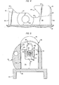
- FIGURE 1 shows a firearm including a barrel 10 having an integral extension 12 formed with a locking recess 16.
- the barrel is formed with a cartridge-receiving chamber 18 terminating rearwardly in a circumferential counterbore 19 for seating the head of the cartridge, and a surface 11 defining a rearwardly-facing open breech.
- the barrel is affixed in a receiver 20, which has a socket 23 at its rear end for mounting a shoulder stock (not shown), and a ring 21 at its forward end for mounting a conventional cartridge magazine tube (not shown).
- An action bar assembly 22 is reciprocably slidable longitudinally of the receiver, and extends forwardly for attachment to conventional manual or gas operating means (not shown) located at the fore-end of the firearm.
- the assembly 22 comprises a pair of parallel action bars interconnected at their rear ends by a transverse web 26, to which a slide block 28 is affixed.
- the slide block has an opening 29 for mounting a manual bolt-operating handle (not shown).
- a breech bolt 30 has a recess 50 extending vertically therethrough, and the slide block 28 is received in this recess for limited longitudinal movement relative to the bolt.
- the limits of this movement are defined by the engagement of a rear surface 49 of the slide block with a forwardly-facing interior surface 52 in the bolt recess, in a rearward relative position of the slide block shown in FIG. 1; and by the engagement of a front surface 44 of the slide block with a rearwardly-facing interior-surface 51 in the bolt recess, in a forward relative position of the slide block shown in FIG. 9.
- the bolt 30 has an axial bore 32, in which a firing pin 34 is reciprocably slidable between a retracted position shown in FIG. 1, in which its tip 35 is withdrawn behind the bolt face 36, and an extended position in which the tip protrudes forwardly from the bolt face, as shown at 35' in FIG. 9, to fire a cartridge (not shown) received in the'chamber 18.
- the firing pin is biased rearwardly by a compression spring 54 bearing against the bolt surface 51 and receiving the firing pin coaxially therethrough.
- the firing pin is retained by a transverse pin 60 extending transversely of the bolt through the bore 32, and cooperating with a flat 62 milled in the firing pin to limit movement of the firing pin with respect to the bolt.
- the firing pin has an enlarged head or abutment 48 formed in its rear end, which protrudes rearwardly.from the bolt in the retracted position of the firing pin.
- a locking block 38 which is also shown on an enlarged scale in FIGS. 2, 3, and 5, is received in the bolt recess 50 above the slide block 28.
- the locking block has an arm 43 which is received in a recess 55 at the rear of the bolt, and on which the locking block is free to pivot between a lowered position shown in FIG. 1, and a locked position shown in FIGS. 7-9, in which a lug 40 formed on the locking block engages in the barrel recess 16.
- the locking block is formed in an inverted U-shape, having a sloping central channel 37 to provide clearance for the firing pin 34 in both the lowered and the locked positions, and a pair of depending parallel web portions 39. These web portions straddle the firing pin and fit into a recess 27 lying between a pair of upstanding cam lugs 45 on the slide block 28, as shown in FIGS. 4 and 5.
- the locking block 38 has flat surfaces 33 at its forward end, which rest on top of the flat upper surfaces of the lugs 45 in the locked position shown in FIGS, 5 and 9.
- Central recesses 42 are formed on either side of the web portions 39, for receiving the lugs 45 in the lowered position of the locking block shown in FIG. 1. Sloping cam surfaces 31 connect the recesses 42 with the flats 33.
- a pair of depending legs 41 provide further sloping cam surfaces 56 at the rear of the recesses 42.
- One of these legs is formed with a blind hole 53 (see FIG. 2) in which a pin (not shown) may be secured to prevent accidental disassembly of the locking block when the bolt assembly is removed from the receiver for cleaning.
- the lugs 45 of the slide block 28, which is shown on an enlarged scale in FIGS. 4 and 5, are formed with sloping cam surfaces 61 joining the front surface 44 with their flat upper surfaces; and with further sloping cam surfaces 57 extending down into a recess 46, which receives the locking block legs 41 in the lowered position of FIG. 1.
- the upper surface of the slide block is relieved at 47 to permit it to move under the locking block 38 into its forward position shown in FIG. 9.
- the slide block 28 is provided with a raised rearward portion 58, which is aligned with the firing pin abutment 48 in the direction of longitudinal reciprocation of the bolt assembly and firing pin.
- a U-shaped recess 59 extends longitudinally through the portion 58, and is sized to receive the body of the firing pin 34 in freely- slidable relation, but to block movement of the abutment 48 forwardly of the surface 49.
- a hammer 66 is pivotally mounted on a pin 68 secured in the receiver 20, and is rotatable clockwise, when. released by a suitable trigger and fire control mechanism (not shown) from a cocked position shown in FIG. 1 to a firing position shown in FIG. 9, in which it impacts the rear end of the firing pin abutment 48 to discharge the firearm.
- a suitable trigger and fire control mechanism (not shown) from a cocked position shown in FIG. 1 to a firing position shown in FIG. 9, in which it impacts the rear end of the firing pin abutment 48 to discharge the firearm.
- an elastomeric plug 24 is secured in a recess 25 at the rear of the receiver.
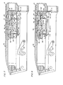
- the action bars 22 and slide block 28 are shown moving forward in FIG. 6; in the direction shown by the arrow.
- the slide block first moves independently of the bolt 30, separating the surfaces 49 and 52; however, the cam surface 61 of the slide block shortly engages the cam surface 31 of the locking block 38, and commences to drive the locking block forwardly. Any tendency to tilt the locking block upwardly at this time is resisted frictionally by the resulting pressure of the forward locking block surface 63 against the interior bolt surface 51; but if this resistance is overcome, the lug 40 will simply slide against the interior of the receiver 20 and barrel extension 12, until the lug reaches the recess 16.
- the bolt 30 is driven forwardly with the locking block until its face 36 seats against the barrel breech surface 11, as shown in FIG. 6.
- the slide block surface 49 is separated slightly from the bolt surface 52.
- the dimensions of the firing pin are such that in its retracted position shown in FIG. 6, its tip 35 lies a distance L2 behind the bolt face 36; while the forward end of the abutment 48 lies a smaller distance Ll behind the slide block surface 49 at the portion 58.
- the hammer 66 is normally held in the illustrated cocked position by the fire-control mechanism during the closing movement. However, if it should be accidentally released at this time, it cannot drive the firing pin farther than the distance Ll, too short a movement to cause the tip 35 to protrude from the bolt face to discharge the firearm. Nor can the firing pin move forward under its own inertia, if the firearm is accidentally dropped, enough to cause a discharge. This will be the case even if the spring 54 and retaining pin 60 are bent, broken, or missing altogether.
- FIG. 8 shows the continuation of forward movement of the slide block 28 through an additional distance I, which will permit the firing pin abutment to be driven forwardly a maximum total distance L2 plus I.
- the tip 35 can be made to protrude from the bolt face to indent and ignite the primer of a cartridge (not shown) seated in the chamber 18.
- the maximum primer indent distance is I.
- FIG. 10 illustrates the initiation of reverse movement of the bolt assembly to reopen the breech and recock the hammer after firing.
- the action bars 22 are driven to the rear, as shown by the arrow, by either manual or gas operation as the case may be. This initially retracts only the slide block 28, as the upper surfaces of the lugs 45 slide freely under the locking block surfaces 33.
- the slide block has retreated to the position of FIG. 8, its rearward portion 58 engages the abutment 48 and forcibly retracts the firing pin 34.
- the slide block reaches its rearward relative position with respect to the bolt, with the surfaces 49 and 52 abutting, and the continuing retraction of the slide block is thereafter imparted to the bolt and locking block as well.
- the opening movement of the bolt causes it to push the hammer counterclockwise, and recocking is completed by subsequent rearward movement of the action bar web 26 over the hammer to the position of FIG. 1, when the hammer is held cocked by the aforementioned fire control.
- the rear surface 49 of the slide block portion 58 is positioned even closer to the firing pin abutment 48 than is necessary to ensure that the locking block lug 40 must be fully engaged in the barrel recess 16 before the firing pin tip 35 can be made to protrude from the bolt face 36 to discharge the weapon. This provides a margin of extra safety in the event that the parts, particularly the abutment 48, the slide block portion 58, and the cam surfaces 31 and 61, might become worn or distorted.
- FIGS. 7 and 8 The dimensional relationships involved in this delay in removal of the firing pin block are illustrated in FIGS. 7 and 8.
- the parts are so dimensioned that at the stage of completing the upward movement of the lug 40 into the locking recess shown in FIG. 7, when the cam surface 61 has finished its sliding motion over the cam surface 31 and the locking block surface 33 rests on the lugs 45, the rearward portion 58 of the slide block 28 is spaced ahead of the abutment 48 only the same distance L2 that the firing pin tip 35 lies behind the bolt face 36.
Landscapes
- Engineering & Computer Science (AREA)
- General Engineering & Computer Science (AREA)
- Portable Nailing Machines And Staplers (AREA)
Applications Claiming Priority (2)
| Application Number | Priority Date | Filing Date | Title |
|---|---|---|---|
| US06/121,436 US4344246A (en) | 1980-02-14 | 1980-02-14 | Firing pin block for firearm having a reciprocating breech bolt |
| US121436 | 1980-02-14 |
Publications (3)
| Publication Number | Publication Date |
|---|---|
| EP0034475A2 true EP0034475A2 (fr) | 1981-08-26 |
| EP0034475A3 EP0034475A3 (en) | 1982-04-07 |
| EP0034475B1 EP0034475B1 (fr) | 1984-08-08 |
Family
ID=22396720
Family Applications (1)
| Application Number | Title | Priority Date | Filing Date |
|---|---|---|---|
| EP81300589A Expired EP0034475B1 (fr) | 1980-02-14 | 1981-02-13 | Dispositif de percussion pour arme à feu avec culasse à glissement longitudinal |
Country Status (7)
| Country | Link |
|---|---|
| US (1) | US4344246A (fr) |
| EP (1) | EP0034475B1 (fr) |
| JP (1) | JPS56122000A (fr) |
| AU (1) | AU534704B2 (fr) |
| CA (1) | CA1151922A (fr) |
| DE (1) | DE3165311D1 (fr) |
| ES (1) | ES8206835A1 (fr) |
Families Citing this family (19)
| Publication number | Priority date | Publication date | Assignee | Title |
|---|---|---|---|---|
| CA1231571A (fr) * | 1983-11-29 | 1988-01-19 | William B. Ruger | Selecteur de neutralisation pour armes a feu a culasse mobile |
| US5259137A (en) * | 1991-09-27 | 1993-11-09 | Horst Blaser Jagdwaffenfabrik | Breech mechanism for a firearm especially a repeater weapon |
| US6378237B1 (en) * | 1997-12-05 | 2002-04-30 | Surefire, Llc | Firearms with target illuminators |
| US6993864B1 (en) * | 2003-02-11 | 2006-02-07 | Smith & Wesson Corp. | Locking block for compact semi-automatic pistols |
| ATE544998T1 (de) * | 2003-05-23 | 2012-02-15 | Ra Brands Llc | Verschlussanordnung mit verriegelungssystem |
| US7181880B2 (en) * | 2003-10-31 | 2007-02-27 | Ra Brands, L.L.C. | Roller sear/hammer interface for firearms |
| ATE545000T1 (de) * | 2003-10-31 | 2012-02-15 | Ra Brands Llc | Kopplung zwischen schlaghammer und abzugshebel mittels eines rollers |
| US7076908B2 (en) * | 2003-11-13 | 2006-07-18 | Surefire, Llc | Accessory mount for a firearm |
| US7334365B2 (en) * | 2005-01-20 | 2008-02-26 | Surefire, Llc | Accessory mount for a firearm |
| US7334366B2 (en) * | 2005-10-05 | 2008-02-26 | Surefire, Llc | Accessory mount for a firearm |
| US7395627B2 (en) * | 2006-03-29 | 2008-07-08 | Surefire, Llc | Accessory mount for a firearm |
| US8296990B2 (en) * | 2008-12-30 | 2012-10-30 | Smith & Wesson Corp. | Snap-on dovetail pistol sight |
| US8733009B2 (en) | 2012-01-06 | 2014-05-27 | Ra Brands, L.L.C. | Magazine cutoff |
| US8800422B2 (en) | 2012-08-20 | 2014-08-12 | Ra Brands, L.L.C. | Bolt assembly for firearms |
| US9417019B2 (en) | 2012-08-24 | 2016-08-16 | Ra Brands, L.L.C. | Fire control for auto-loading shotgun |
| ITRM20130425A1 (it) * | 2013-07-18 | 2015-01-19 | Piergiorgio Cataldi | Meccanismo di riarmo per armi semiautomatiche da caccia e/o da tiro |
| US9810496B2 (en) * | 2014-05-15 | 2017-11-07 | Savage Arms, Inc. | Semiautomatic firearm |
| WO2019139889A1 (fr) * | 2018-01-09 | 2019-07-18 | Sturm, Ruger & Company, Inc. | Arme à feu à action de pompe avec mécanisme de verrouillage à glissière |
| RU2702547C1 (ru) * | 2018-10-22 | 2019-10-08 | Василий Михайлович Покаляев | Автоматическое (самозарядное) огнестрельное оружие с инерционной системой автоматики |
Family Cites Families (6)
| Publication number | Priority date | Publication date | Assignee | Title |
|---|---|---|---|---|
| US2418946A (en) * | 1942-08-15 | 1947-04-15 | Remington Arms Co Inc | Breech bolt lock for firearms |
| US2601808A (en) * | 1948-09-15 | 1952-07-01 | Howard R Clarke | Breech bolt lock and actuator for firearms |
| US2570772A (en) * | 1949-03-03 | 1951-10-09 | Remington Arms Co Inc | Recoil operated firearm with pivoted bolt lock |
| US2645873A (en) * | 1950-01-31 | 1953-07-21 | Remington Arms Co Inc | Slide-actuated firearm with tilting locking block |
| GB1441761A (en) * | 1973-08-03 | 1976-07-07 | Kawamura T | Lock device in a shot gun |
| US4161836A (en) * | 1976-11-25 | 1979-07-24 | Kabushiki Kaisha Kawaguchiya Hayashi Juho Kayaku-Ten | Breechblock assembly and an operating mechanism for a fire-arm automatic loading |
-
1980
- 1980-02-14 US US06/121,436 patent/US4344246A/en not_active Expired - Lifetime
-
1981
- 1981-01-16 CA CA000368709A patent/CA1151922A/fr not_active Expired
- 1981-02-05 JP JP1511181A patent/JPS56122000A/ja active Pending
- 1981-02-12 AU AU67243/81A patent/AU534704B2/en not_active Ceased
- 1981-02-13 ES ES499444A patent/ES8206835A1/es not_active Expired
- 1981-02-13 EP EP81300589A patent/EP0034475B1/fr not_active Expired
- 1981-02-13 DE DE8181300589T patent/DE3165311D1/de not_active Expired
Also Published As
| Publication number | Publication date |
|---|---|
| JPS56122000A (en) | 1981-09-25 |
| EP0034475A3 (en) | 1982-04-07 |
| AU6724381A (en) | 1981-08-20 |
| US4344246A (en) | 1982-08-17 |
| DE3165311D1 (en) | 1984-09-13 |
| ES499444A0 (es) | 1982-08-16 |
| ES8206835A1 (es) | 1982-08-16 |
| CA1151922A (fr) | 1983-08-16 |
| EP0034475B1 (fr) | 1984-08-08 |
| AU534704B2 (en) | 1984-02-09 |
Similar Documents
| Publication | Publication Date | Title |
|---|---|---|
| EP0034475B1 (fr) | Dispositif de percussion pour arme à feu avec culasse à glissement longitudinal | |
| US4389919A (en) | Firing pin block for firearm with a rotary breech bolt | |
| US9513076B2 (en) | Firearm with reciprocating bolt assembly | |
| EP0550238B1 (fr) | Pistolet à double action comportant un mécanisme de mise à feu amélioré | |
| US7703230B2 (en) | Positive striker lock safety for use with a firearm | |
| US4015512A (en) | Gas-operated firearm | |
| CA2769019C (fr) | Dispositif de culasse pour une arme a feu a main | |
| US5502914A (en) | Striker cocking and firing mechanism for a handgun | |
| CA2290025C (fr) | Mecanisme d'ejection de cartouches pour pistolet automatique modifie | |
| US5235763A (en) | Key-actuated safety for handgun | |
| US4879827A (en) | Single shot falling block action rifle | |
| US11578939B2 (en) | Safety mechanism for firearms | |
| US3090148A (en) | Bolt action firearm with charger | |
| US20030037666A1 (en) | Semi-automatic firing and disconnecting device for a non-hammer fired machine gun | |
| EP0871844B1 (fr) | Systeme de verrouillage de culasse par le chien pour armes a feu a levier de detente | |
| US4341031A (en) | Percussion firing mechanism for industrial guns | |
| US2765561A (en) | Repeating rifle having trigger mechanism on finger lever | |
| US2894346A (en) | Firing mechanism with a single spring for the hammer, hammer catch means and trigger | |
| EP1106955B1 (fr) | Arme à feu avec percuteur inertial | |
| US3129637A (en) | Safety sear mechanism for blow back breech action | |
| US2742822A (en) | Firing mechanism for automatic and semi-automatic firearms | |
| EP0034476A2 (fr) | Dispositif de percussion pour arme à feu à culasse rotative | |
| US3938423A (en) | Recoil operated firearm with unitary barrel and breech bolt lock member | |
| RU2186316C1 (ru) | Полуавтоматический пистолет | |
| EP4621339A1 (fr) | Mécanisme de culasse à traction droite pour fusil à répétition et fusil à répétition |
Legal Events
| Date | Code | Title | Description |
|---|---|---|---|
| PUAI | Public reference made under article 153(3) epc to a published international application that has entered the european phase |
Free format text: ORIGINAL CODE: 0009012 |
|
| AK | Designated contracting states |
Designated state(s): BE DE FR IT |
|
| PUAL | Search report despatched |
Free format text: ORIGINAL CODE: 0009013 |
|
| AK | Designated contracting states |
Designated state(s): BE DE FR IT |
|
| 17P | Request for examination filed |
Effective date: 19820909 |
|
| ITF | It: translation for a ep patent filed | ||
| GRAA | (expected) grant |
Free format text: ORIGINAL CODE: 0009210 |
|
| AK | Designated contracting states |
Designated state(s): BE DE FR IT |
|
| REF | Corresponds to: |
Ref document number: 3165311 Country of ref document: DE Date of ref document: 19840913 |
|
| PGFP | Annual fee paid to national office [announced via postgrant information from national office to epo] |
Ref country code: BE Payment date: 19840930 Year of fee payment: 5 |
|
| ET | Fr: translation filed | ||
| PGFP | Annual fee paid to national office [announced via postgrant information from national office to epo] |
Ref country code: FR Payment date: 19841121 Year of fee payment: 5 |
|
| PGFP | Annual fee paid to national office [announced via postgrant information from national office to epo] |
Ref country code: DE Payment date: 19850226 Year of fee payment: 5 |
|
| PLBE | No opposition filed within time limit |
Free format text: ORIGINAL CODE: 0009261 |
|
| STAA | Information on the status of an ep patent application or granted ep patent |
Free format text: STATUS: NO OPPOSITION FILED WITHIN TIME LIMIT |
|
| 26N | No opposition filed | ||
| PG25 | Lapsed in a contracting state [announced via postgrant information from national office to epo] |
Ref country code: BE Effective date: 19890228 |
|
| BERE | Be: lapsed |
Owner name: REMINGTON ARMS CY INC. Effective date: 19890228 |
|
| PG25 | Lapsed in a contracting state [announced via postgrant information from national office to epo] |
Ref country code: FR Free format text: LAPSE BECAUSE OF NON-PAYMENT OF DUE FEES Effective date: 19891027 |
|
| PG25 | Lapsed in a contracting state [announced via postgrant information from national office to epo] |
Ref country code: DE Effective date: 19891101 |
|
| REG | Reference to a national code |
Ref country code: FR Ref legal event code: ST |