EP0034652A1 - Appareil mobile avec dispositif pour imprimer des informations - Google Patents
Appareil mobile avec dispositif pour imprimer des informations Download PDFInfo
- Publication number
- EP0034652A1 EP0034652A1 EP80106436A EP80106436A EP0034652A1 EP 0034652 A1 EP0034652 A1 EP 0034652A1 EP 80106436 A EP80106436 A EP 80106436A EP 80106436 A EP80106436 A EP 80106436A EP 0034652 A1 EP0034652 A1 EP 0034652A1
- Authority
- EP
- European Patent Office
- Prior art keywords
- paper
- cassette
- receiving chamber
- housing
- information
- Prior art date
- Legal status (The legal status is an assumption and is not a legal conclusion. Google has not performed a legal analysis and makes no representation as to the accuracy of the status listed.)
- Granted
Links
Images
Classifications
-
- G—PHYSICS
- G08—SIGNALLING
- G08B—SIGNALLING SYSTEMS, e.g. PERSONAL CALLING SYSTEMS; ORDER TELEGRAPHS; ALARM SYSTEMS
- G08B3/00—Audible signalling systems, e.g. audible personal calling systems
- G08B3/10—Audible signalling systems, e.g. audible personal calling systems using electric transmission; using electromagnetic transmission
- G08B3/1008—Personal calling arrangements or devices, i.e. paging systems
- G08B3/1016—Personal calling arrangements or devices, i.e. paging systems using wireless transmission
- G08B3/1025—Paging receivers with audible signalling details
- G08B3/105—Paging receivers with audible signalling details with call or message storage means
-
- G—PHYSICS
- G06—COMPUTING OR CALCULATING; COUNTING
- G06K—GRAPHICAL DATA READING; PRESENTATION OF DATA; RECORD CARRIERS; HANDLING RECORD CARRIERS
- G06K15/00—Arrangements for producing a permanent visual presentation of the output data, e.g. computer output printers
- G06K15/02—Arrangements for producing a permanent visual presentation of the output data, e.g. computer output printers using printers
- G06K15/10—Arrangements for producing a permanent visual presentation of the output data, e.g. computer output printers using printers by matrix printers
-
- G—PHYSICS
- G06—COMPUTING OR CALCULATING; COUNTING
- G06K—GRAPHICAL DATA READING; PRESENTATION OF DATA; RECORD CARRIERS; HANDLING RECORD CARRIERS
- G06K17/00—Methods or arrangements for effecting co-operative working between equipments covered by two or more of main groups G06K1/00 - G06K15/00, e.g. automatic card files incorporating conveying and reading operations
-
- G—PHYSICS
- G08—SIGNALLING
- G08B—SIGNALLING SYSTEMS, e.g. PERSONAL CALLING SYSTEMS; ORDER TELEGRAPHS; ALARM SYSTEMS
- G08B3/00—Audible signalling systems, e.g. audible personal calling systems
- G08B3/10—Audible signalling systems, e.g. audible personal calling systems using electric transmission; using electromagnetic transmission
- G08B3/1008—Personal calling arrangements or devices, i.e. paging systems
- G08B3/1016—Personal calling arrangements or devices, i.e. paging systems using wireless transmission
-
- H—ELECTRICITY
- H04—ELECTRIC COMMUNICATION TECHNIQUE
- H04B—TRANSMISSION
- H04B1/00—Details of transmission systems, not covered by a single one of groups H04B3/00 - H04B13/00; Details of transmission systems not characterised by the medium used for transmission
- H04B1/06—Receivers
- H04B1/08—Constructional details, e.g. cabinet
- H04B1/082—Constructional details, e.g. cabinet to be used in vehicles
-
- H—ELECTRICITY
- H05—ELECTRIC TECHNIQUES NOT OTHERWISE PROVIDED FOR
- H05K—PRINTED CIRCUITS; CASINGS OR CONSTRUCTIONAL DETAILS OF ELECTRIC APPARATUS; MANUFACTURE OF ASSEMBLAGES OF ELECTRICAL COMPONENTS
- H05K11/00—Combinations of a radio or television receiver with apparatus having a different main function
- H05K11/02—Combinations of a radio or television receiver with apparatus having a different main function with vehicles
Definitions
- the invention relates to a mobile device, in particular a radio device intended for carrying and / or for fixed attachment in vehicles, according to the preamble of the main claim.
- a mobile device in particular a radio device intended for carrying and / or for fixed attachment in vehicles, according to the preamble of the main claim.
- radio devices information can only be transmitted if a communication person is present on both the transmitter and the receiver side. However, when the recipient is absent, it is not possible to receive information and save it for later retrieval.
- the radio channel used is occupied by other radio users. Because of the redundancy contained in the language, these occupancy times are relatively long in comparison to the volume of information transmitted in this way, so that the radio channels, which are only available in limited numbers anyway, are not used very efficiently.
- the device according to the invention with the characterizing features of the main claim has the advantage that information can also be transmitted to a specific recipient if the recipient is not directly present on the device. This information is recorded and saved in the absence of the recipient and can be read by the recipient at any time.
- An essential advantage of the device according to the invention lies in the considerable reduction in the occupancy time of the radio channel for the transmission of certain information. This is because the invention makes it possible to standardize information as alphanumeric texts and to transmit it in coded form in the shortest possible time. At the point of reception, the information is stored, decoded and recorded as alphanumeric text without the intelligibility of the transmitted information suffering.
- the reduction factor as the ratio of the transmission time for speech to the transmission time for alphanumeric text for the same information can easily reach up to 10: 1.
- the gain factor of the channel assignment can be up to 5, which means that the number of participants for a radio channel can be increased by four to five.
- the device according to the invention also has the advantage that it can be constructed in an extremely compact and space-saving manner, which creates the conditions for its implementation as a portable radio or as a vehicle radio.
- the embodiment of the invention according to claim 2 is particularly advantageous here. These measures not only allow a high degree of compactness, but also, at the same time, considerable ease of use combined with ease of servicing the device.
- the embodiment of the invention according to claim 4 is particularly advantageous.
- Such an RMP printer is robust and largely insensitive to shock and vibration, so that it is ideally suited for rough operation in a motor vehicle.
- the stock of registration metal paper can be replaced easily and quickly.
- the registration-metal-paper (RMP) printer which is normally combined with the device, can also be produced as a compact printer housed in a separate housing, which printer can be connected, for example, to a data terminal.
- RMP registration-metal-paper
- the embodiment of the invention according to claim 5 is also advantageous. This allows an even further simplification in the handling of the slide-in cassette for paper renewal.
- the embodiment of the invention according to claim 9 is also advantageous. This results in a further robustness and vibration resistance of the device according to the invention, especially with regard to the information recording device.
- the connected to the receiving part Assemblies, such as the writing electrodes, are arranged in a fixed position in the receiving chamber and can be contacted well and without interference.
- the embodiment of the invention according to claim 11 is particularly advantageous.
- the automatic lifting of the writing electrodes when pulling out or inserting the insertion cassette from or into the receiving chamber means that the writing electrodes cannot be mechanically damaged, which considerably increases their service life.
- the embodiment of the invention according to claim 12 is particularly advantageous.
- the electrodes are automatically cleaned when the insert cassette is pulled out or pushed in, so that the text printed by the writing electrodes on the metal paper always gives a clear typeface and can be read effortlessly.
- a particularly advantageous embodiment of the invention results from claim 14, in particular in connection with claim 15. This creates a device with extremely small dimensions, which can be integrated particularly well into the dashboard of a motor vehicle.
- the structure of the printer according to the invention avoids RF interference when recording.
- the attachment of the conductive counterelectrode in front of the writing electrodes contributes to this.
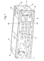
- the device shown in Fig. 1 is particularly suitable for fixed mounting in the dashboard or in the dash area of a motor vehicle.
- the device has a housing 10 which is closed at the front with a front plate 11 which carries an operating keyboard 12.
- a receiving part 13 is arranged in the housing 10, which is indicated schematically in FIG. 1.
- the housing 10 has a receiving chamber 14 that is accessible from one side of the front plate 11.
- An insertion cassette 15 can be pushed into this receiving chamber 14 or pulled out of the receiving chamber 14.
- An information recording device 16 is with its assemblies and / or components on the receiving chamber 14 and one slide cassette 15 divided, the assemblies and / or components are arranged in mutual association in the receiving chamber 14 and in the insertion cassette 15.
- the information recording device 16 thus completely integrated into the housing 10 is electrically connected to the receiving part 13.
- the information recording device 16 is designed as a registration metal-paper printer, hereinafter referred to as the RMP printer 17.
- the record carrier is in the form of a tape and is formed by a so-called registration metal paper 18 which bears a metal covering in which the information is burned in by means of writing electrodes.
- the information is recorded correctly in the longitudinal direction of the record carrier or the tape-like paper 18 in several adjacent columns.
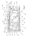
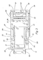
- the RMP printer 17 also has a roller-shaped counterelectrode 20, which extends over the entire paper width (seen transversely to the paper transport direction), a paper supply space 21 and a paper transport device 22 with a drive motor 23 and a drive shaft 24 which transports the paper 18 (FIG . 2 and 3).
- the writing electrodes 19 and the counter electrode 20 are held in the interior of the receiving chamber 14, while the paper supply space 21 and the paper transport device 22 are arranged in the insertion cassette 15.
- the receiving chamber 14 is formed by a sleeve 27 which is approximately U-shaped in cross section and is open at the top, the side walls 28 and 29 of which are angled at their upper, free end.
- the side wall 28 is at right angles to the inside of the sleeve 27 and the side wall 29 is angled at right angles to the outside.
- the Bottom 30 of the sleeve 27 can be glued to the bottom of the housing 10.
- the receiving chamber 14 or the sleeve 27 extends along a narrow side 25 of the housing 10 oriented at right angles to the front plate 11 and can additionally be held on the narrow side 25 via bolts 31, 32.
- two parallel spring supports 26 and 33 are attached, which extend in the longitudinal direction of the sleeve 27 and the receiving chamber 14.
- the writing electrodes 19 of the RMP printer 17 are arranged in a fixed manner, the writing pens 34 pointing downward.
- the spring cantilever 33 which also extends beyond the spring cantilever 26 and is longer than the spring cantilever 26, carries at its free end the roller-shaped counterelectrode 20, which is rotatably mounted on the latter.
- the spring support 26 carrying the writing electrodes 19 has a protruding lifting tongue 35 on both sides, which, when the insertion cassette is inserted or withdrawn into or out of the receiving chamber 14, rests on the upper side 36 of the insertion cassette 15 and, when the insertion cassette 15 is fully inserted, into one recess 37 provided in the upper side 36 of the insert cassette. In this way, the spring support 26 and thus the writing electrodes 19 are raised when the insertion cassette 15 is pulled out or pushed in, so that the latter gain distance from the drive shaft 24 of the paper transport device 22 and cannot be damaged.
- the insertion cassette 15, which is adapted in shape to the receiving chamber 14, is box-shaped and essentially open towards the upper side 36. She shows the paper Storage space 21 as a pocket 38 accessible from above, into which a paper roll 39 can be inserted interchangeably.
- the paper transport device 22 with the drive motor 23 and the drive shaft 24 is arranged downstream of the insertion compartment 38 in the insertion direction of the insertion cassette 15.
- the drive motor 23 is designed as a geared motor and has a reduction gear 40 which is connected between the drive shaft 24 and the drive motor 23.
- the writing electrodes 19 with their writing pens 34 rest on the circumference of the drive shaft 24.
- the paper 18 is pulled off the paper roll 39 and runs on the upper side 36 of the slide-in cassette 15, is passed between the pens 34 of the writing electrodes 19 and the drive shaft 24 and the counterelectrode 20 and the drive shaft 24 and enters, as in FIG. 1 can be seen from the front of the receiving chamber 14 and the insert cassette 15 towards the front plate 11 of the device.
- a sawtooth-like tear-off edge 41 is provided on the receiving chamber 14, by means of which any length of paper carrying the recorded information can be cut off.
- the paper roll 39 is arranged in a capsule 42 and is rotatably mounted on an axial center pin 43 of the capsule 42.
- the capsule 42 consists of two symmetrical halves which can be plugged onto one another in the direction of the center pin 43.
- the rear half of the capsule 42 can be seen in FIG.
- the capsule 42 has an axially parallel, slot-shaped outlet opening 44 through which the paper 18 can be passed.
- the capsule 42 To insert a paper roll 39, the capsule 42 must be pulled apart in the direction of its axis.
- the paper roll 39 is to be placed on the center pin 43 projecting from one part of the capsule 42 and the paper 18 is pulled through the outlet opening 44.
- the second part of the capsule is then to be pushed onto the first part, whereby it is positioned correctly by the center pin 43 and further positioning pins 48.
- the capsule 42 is then inserted into the paper supply space 21 from the upper side 36 of the insertion cassette 15, the scanning sensor 46 of the paper supply display device 47 passing through the gap 45 and resting on the circumference of the paper roll 39.
- the paper supply display device 47 also has an indicator lamp 49 in the form of an LED which is arranged in the receiving chamber 14, namely on the front side thereof. This is in a circuit via a breaker, not shown.
- the interrupter is actuated by the sensing sensor 46 in such a way that it is normally kept open - so that the circuit is interrupted - and closed at a predetermined minimum diameter of the paper roll 39 and so that the indicator lamp 49 is switched on.
- contact surfaces 51 are arranged on the insert cassette 15, namely on its front end face 50 seen in the insertion direction with the break contact of the paper supply display device 47 and with the paper transport device 22 are electrically conductively connected.
- Contact springs 52 are provided in the receiving chamber 14, each of which is assigned to one of the contact surfaces 51. These contact springs are connected to the power supply or to the indicator lamp 49 of the paper supply display device 47, so that the circuit for the paper transport device 22 and the paper supply display device 47 is closed via the contact springs 52 resting on the associated contact surfaces 51 when the insert cassette 15 is inserted is.
- an ejection spring 59 engages on the front face 50 of the insert cassette 15 as viewed in the insertion direction, which is tensioned by the insertion process and is held in its tensioned position by the insert cassette 15 locked in the inserted position.
- the ejection spring 59 pushes the insertion cassette 15 partially out of the receiving chamber 14, so that the operator can easily grip the insertion cassette 15 on the front of the device.
- a brush 53 projecting upwards is arranged on the upper side 36 of the slide-in cassette 15, specifically close to the front end face 50 as seen in the slide-in direction.
- the brush 53 extends at least over a width which corresponds to the total width of the writing electrodes 19 lying next to one another transversely to the paper transport direction.
- a paper collecting box 55 covering the front opening, ie the insertion opening 54, of the receiving chamber 14 can also be arranged removably on the front side or on the front plate 11 of the housing 10.
- this paper collecting box 55 the paper material drawn off by the drive shaft 24 from the paper roll 39 and labeled by the RMP printer 17 is deposited and, after the paper collecting box 55 has been pulled off, can be removed from the front plate 11 of the housing 10 and removed via the tear-off edge 41 from the Paper roll 39 are separated.
- information is transmitted to the receiving part 13 in a continuous sequence of signals in coded form, preferably in ASCII code.
- An information memory is provided in the vaccination section, in which the received signals are initially stored in coded form.
- a read-out and control unit which is connected both to the information memory and to the write electrodes 19 of the RMP printer 17, ensures that the information is read from the memory in the correct order and decoded and in the correct order the write electrodes 19 of the RMP printer 17 can be controlled.
- the information memory and the readout and control unit are not shown in FIG. 1. These are arranged on a circuit board 56 located outside the receiving chamber 14 in the housing 10.
- the information retrieved from the memory is recorded on the metal paper 18 in the longitudinal direction of the recording medium, that is to say in the transport direction of the metal paper 18 in columns lying adjacent to one another transversely to the transport direction of the paper 18.
- a write head 57 is provided for each column are summarized in which the number of required write electrodes 19 with their S c h reibstatten 34th In the printing of the signals transmitted in ASCII code 57 seven write electrodes are arranged fixedly next to one another transversely to the paper transport 19 p o rtraum per write head.
Landscapes
- Engineering & Computer Science (AREA)
- Physics & Mathematics (AREA)
- General Physics & Mathematics (AREA)
- Computer Networks & Wireless Communication (AREA)
- Theoretical Computer Science (AREA)
- Electromagnetism (AREA)
- Mathematical Physics (AREA)
- General Engineering & Computer Science (AREA)
- Signal Processing (AREA)
- Microelectronics & Electronic Packaging (AREA)
- Accessory Devices And Overall Control Thereof (AREA)
- Time Recorders, Dirve Recorders, Access Control (AREA)
- Facsimiles In General (AREA)
Priority Applications (1)
| Application Number | Priority Date | Filing Date | Title |
|---|---|---|---|
| AT80106436T ATE14050T1 (de) | 1980-02-15 | 1980-10-22 | Mobiles geraet mit informa tionsaufzeichnungsvorrichtung. |
Applications Claiming Priority (2)
| Application Number | Priority Date | Filing Date | Title |
|---|---|---|---|
| DE3005612 | 1980-02-15 | ||
| DE19803005612 DE3005612A1 (de) | 1980-02-15 | 1980-02-15 | Mobiles geraet |
Publications (2)
| Publication Number | Publication Date |
|---|---|
| EP0034652A1 true EP0034652A1 (fr) | 1981-09-02 |
| EP0034652B1 EP0034652B1 (fr) | 1985-06-26 |
Family
ID=6094646
Family Applications (1)
| Application Number | Title | Priority Date | Filing Date |
|---|---|---|---|
| EP80106436A Expired EP0034652B1 (fr) | 1980-02-15 | 1980-10-22 | Appareil mobile avec dispositif pour imprimer des informations |
Country Status (4)
| Country | Link |
|---|---|
| EP (1) | EP0034652B1 (fr) |
| AT (1) | ATE14050T1 (fr) |
| CH (1) | CH649425A5 (fr) |
| DE (2) | DE3005612A1 (fr) |
Cited By (3)
| Publication number | Priority date | Publication date | Assignee | Title |
|---|---|---|---|---|
| FR2559289A1 (fr) * | 1984-02-07 | 1985-08-09 | Ricard Claude | Taximetre electronique |
| EP0265708A3 (en) * | 1986-10-25 | 1988-09-14 | Mannesmann Kienzle Gmbh | Lead-sealable housing for a taximeter printer and data memory module |
| EP1481481A4 (fr) * | 2002-02-13 | 2006-09-20 | Silverbrook Res Pty Ltd | Recepteur et appareil d'impression associe |
Families Citing this family (2)
| Publication number | Priority date | Publication date | Assignee | Title |
|---|---|---|---|---|
| DE9315569U1 (de) * | 1993-10-07 | 1994-01-13 | Bueser Markus | Rundfunkgerät |
| AU2003202649B2 (en) * | 2002-02-13 | 2005-10-27 | Silverbrook Research Pty Ltd | Receiver and associated printing apparatus |
Citations (1)
| Publication number | Priority date | Publication date | Assignee | Title |
|---|---|---|---|---|
| US3846783A (en) * | 1973-03-12 | 1974-11-05 | Eikonix Corp | Remote paging with message storage |
Family Cites Families (5)
| Publication number | Priority date | Publication date | Assignee | Title |
|---|---|---|---|---|
| US3944724A (en) * | 1972-05-18 | 1976-03-16 | Texas Instruments Incorporated | Paging system with selectively actuable pocket printers |
| US4095215A (en) * | 1975-05-22 | 1978-06-13 | Sanders Associaties, Inc. | Pager subsystems |
| US3996581A (en) * | 1975-05-22 | 1976-12-07 | Sanders Associates, Inc. | Hard copy tone address paging system |
| DE2606691C3 (de) * | 1976-02-19 | 1979-05-03 | Bjoern 3100 Celle Bluethgen | Nachrichtenkommunikationssystem, insbesondere Personenrufsystem |
| DE2610936C3 (de) * | 1976-03-16 | 1980-07-24 | Robert Bosch Gmbh, 7000 Stuttgart | Schreibvorrichtung zur zeilenweisen Wiedergabe der Anzeige eines elektronischen Taschenrechners o.dgl. elektronischen Kleingerätes |
-
1980
- 1980-02-15 DE DE19803005612 patent/DE3005612A1/de not_active Withdrawn
- 1980-10-22 AT AT80106436T patent/ATE14050T1/de not_active IP Right Cessation
- 1980-10-22 DE DE8080106436T patent/DE3070814D1/de not_active Expired
- 1980-10-22 EP EP80106436A patent/EP0034652B1/fr not_active Expired
- 1980-11-07 CH CH8278/80A patent/CH649425A5/de not_active IP Right Cessation
Patent Citations (1)
| Publication number | Priority date | Publication date | Assignee | Title |
|---|---|---|---|---|
| US3846783A (en) * | 1973-03-12 | 1974-11-05 | Eikonix Corp | Remote paging with message storage |
Cited By (3)
| Publication number | Priority date | Publication date | Assignee | Title |
|---|---|---|---|---|
| FR2559289A1 (fr) * | 1984-02-07 | 1985-08-09 | Ricard Claude | Taximetre electronique |
| EP0265708A3 (en) * | 1986-10-25 | 1988-09-14 | Mannesmann Kienzle Gmbh | Lead-sealable housing for a taximeter printer and data memory module |
| EP1481481A4 (fr) * | 2002-02-13 | 2006-09-20 | Silverbrook Res Pty Ltd | Recepteur et appareil d'impression associe |
Also Published As
| Publication number | Publication date |
|---|---|
| EP0034652B1 (fr) | 1985-06-26 |
| CH649425A5 (de) | 1985-05-15 |
| ATE14050T1 (de) | 1985-07-15 |
| DE3070814D1 (en) | 1985-08-01 |
| DE3005612A1 (de) | 1981-09-10 |
Similar Documents
| Publication | Publication Date | Title |
|---|---|---|
| DE69420442T2 (de) | Tragbarer, mit einer Karte kombinierter Fernsprechapparat | |
| DE69704979T2 (de) | Druckgerät mit mehreren Druckeinrichtungen | |
| DE9017815U1 (de) | Drucker mit einem in der Druckträgerebene geteilten Druckergehäuse | |
| DE2719778B2 (de) | Bandaufnahme- und Wiedergabegerät | |
| DE2047386C3 (de) | Vorrichtung zur automatischen Betätigung einer aus einer Anordnung von Tonbandkassetten ausgewählten Tonbandkassette | |
| DE19601004C2 (de) | Datenverarbeitungsvorrichtung mit einem Schubfach und Bildleseköpfen oder Druckköpfen | |
| EP0034652A1 (fr) | Appareil mobile avec dispositif pour imprimer des informations | |
| EP0630509B1 (fr) | Tiroir-caisse | |
| WO1986001328A1 (fr) | Boite pour disques | |
| DE2210818A1 (de) | Verfahren und einrichtung zum abspielen eines scheibenfoermigen, insbesondere folienfoermigen, aufzeichnungstraegers sowie eine traegerplatte zur durchfuehrung des verfahrens | |
| DE3502541C2 (de) | Filmdatenlesevorrichtung für eine Kamera | |
| DE3017469A1 (de) | Mehrfachausdruck-dateneingabeeinrichtung | |
| EP0626095A1 (fr) | Support a compartiments pour cassettes contenant des supports d'enregistrement | |
| WO2002010042A1 (fr) | Magasin de cartes en plastique pour le stockage intermediaire de cartes en plastique dans des installations de traitement de cartes en plastique | |
| DE2920787A1 (de) | Kamera | |
| DE2618309A1 (de) | Transportvorrichtung fuer den registrierstreifen eines schreibenden messgeraetes | |
| EP0470094B1 (fr) | Dispositif d'impression d'images | |
| EP0330847B1 (fr) | Imprimante, en particulier pour titre de transport | |
| EP0859542A2 (fr) | Unité d'alimentation poun un appareil automatique de montage | |
| DE2152361C3 (de) | Statischer Lochkartenleser | |
| DD142102A5 (de) | Plattenspieler | |
| DE2642157A1 (de) | Datenerfassungseinrichtung | |
| EP0458166B1 (fr) | Dispositif de contact pour un interrupteur | |
| EP0791898A2 (fr) | Tachygraphe ou dispositif de lecture/écriture associé au tachygraphe pour l'utilisation des cartes de données relatives au conducteur | |
| DE2902207A1 (de) | Druckgeraet |
Legal Events
| Date | Code | Title | Description |
|---|---|---|---|
| PUAI | Public reference made under article 153(3) epc to a published international application that has entered the european phase |
Free format text: ORIGINAL CODE: 0009012 |
|
| AK | Designated contracting states |
Designated state(s): AT DE FR IT NL |
|
| 17P | Request for examination filed |
Effective date: 19820212 |
|
| ITF | It: translation for a ep patent filed | ||
| GRAA | (expected) grant |
Free format text: ORIGINAL CODE: 0009210 |
|
| AK | Designated contracting states |
Designated state(s): AT DE FR IT NL |
|
| REF | Corresponds to: |
Ref document number: 14050 Country of ref document: AT Date of ref document: 19850715 Kind code of ref document: T |
|
| REF | Corresponds to: |
Ref document number: 3070814 Country of ref document: DE Date of ref document: 19850801 |
|
| ET | Fr: translation filed | ||
| PLBE | No opposition filed within time limit |
Free format text: ORIGINAL CODE: 0009261 |
|
| STAA | Information on the status of an ep patent application or granted ep patent |
Free format text: STATUS: NO OPPOSITION FILED WITHIN TIME LIMIT |
|
| 26N | No opposition filed | ||
| PGFP | Annual fee paid to national office [announced via postgrant information from national office to epo] |
Ref country code: DE Payment date: 19881018 Year of fee payment: 9 |
|
| PGFP | Annual fee paid to national office [announced via postgrant information from national office to epo] |
Ref country code: AT Payment date: 19890926 Year of fee payment: 10 |
|
| ITTA | It: last paid annual fee | ||
| PGFP | Annual fee paid to national office [announced via postgrant information from national office to epo] |
Ref country code: NL Payment date: 19891031 Year of fee payment: 10 |
|
| PG25 | Lapsed in a contracting state [announced via postgrant information from national office to epo] |
Ref country code: FR Effective date: 19900629 |
|
| PG25 | Lapsed in a contracting state [announced via postgrant information from national office to epo] |
Ref country code: DE Effective date: 19900703 |
|
| REG | Reference to a national code |
Ref country code: FR Ref legal event code: ST |
|
| PG25 | Lapsed in a contracting state [announced via postgrant information from national office to epo] |
Ref country code: AT Effective date: 19901022 |
|
| PG25 | Lapsed in a contracting state [announced via postgrant information from national office to epo] |
Ref country code: NL Effective date: 19910501 |
|
| NLV4 | Nl: lapsed or anulled due to non-payment of the annual fee |