EP0034656A1 - Plateforme de pesage et procédé pour la fabrication de telles plates-formes de pesage - Google Patents
Plateforme de pesage et procédé pour la fabrication de telles plates-formes de pesage Download PDFInfo
- Publication number
- EP0034656A1 EP0034656A1 EP80107686A EP80107686A EP0034656A1 EP 0034656 A1 EP0034656 A1 EP 0034656A1 EP 80107686 A EP80107686 A EP 80107686A EP 80107686 A EP80107686 A EP 80107686A EP 0034656 A1 EP0034656 A1 EP 0034656A1
- Authority
- EP
- European Patent Office
- Prior art keywords
- platform
- slots
- strain gauges
- scale according
- elements
- Prior art date
- Legal status (The legal status is an assumption and is not a legal conclusion. Google has not performed a legal analysis and makes no representation as to the accuracy of the status listed.)
- Granted
Links
- 238000000034 method Methods 0.000 title claims description 7
- 230000035945 sensitivity Effects 0.000 claims abstract description 12
- 230000001681 protective effect Effects 0.000 claims description 9
- 125000006850 spacer group Chemical group 0.000 claims description 9
- 238000004519 manufacturing process Methods 0.000 claims description 8
- 239000000463 material Substances 0.000 claims description 5
- 230000005484 gravity Effects 0.000 claims 1
- 238000005303 weighing Methods 0.000 description 14
- 238000005452 bending Methods 0.000 description 13
- 238000010276 construction Methods 0.000 description 10
- 238000009826 distribution Methods 0.000 description 5
- 229910052751 metal Inorganic materials 0.000 description 5
- 239000002184 metal Substances 0.000 description 5
- 230000000694 effects Effects 0.000 description 4
- 238000005553 drilling Methods 0.000 description 3
- 230000006835 compression Effects 0.000 description 2
- 238000007906 compression Methods 0.000 description 2
- 238000010586 diagram Methods 0.000 description 2
- 239000012858 resilient material Substances 0.000 description 2
- 229910000838 Al alloy Inorganic materials 0.000 description 1
- 238000012935 Averaging Methods 0.000 description 1
- 229910001208 Crucible steel Inorganic materials 0.000 description 1
- 241001295925 Gegenes Species 0.000 description 1
- 241000257303 Hymenoptera Species 0.000 description 1
- 239000000853 adhesive Substances 0.000 description 1
- 230000001070 adhesive effect Effects 0.000 description 1
- 229910052782 aluminium Inorganic materials 0.000 description 1
- XAGFODPZIPBFFR-UHFFFAOYSA-N aluminium Chemical compound [Al] XAGFODPZIPBFFR-UHFFFAOYSA-N 0.000 description 1
- 238000013461 design Methods 0.000 description 1
- 239000003000 extruded plastic Substances 0.000 description 1
- 230000002349 favourable effect Effects 0.000 description 1
- 238000003754 machining Methods 0.000 description 1
- 238000012545 processing Methods 0.000 description 1
- 230000035939 shock Effects 0.000 description 1
- 238000003860 storage Methods 0.000 description 1
- 238000012360 testing method Methods 0.000 description 1
- 101150112970 up gene Proteins 0.000 description 1
Images

Classifications
-
- G—PHYSICS
- G01—MEASURING; TESTING
- G01G—WEIGHING
- G01G3/00—Weighing apparatus characterised by the use of elastically-deformable members, e.g. spring balances
- G01G3/12—Weighing apparatus characterised by the use of elastically-deformable members, e.g. spring balances wherein the weighing element is in the form of a solid body stressed by pressure or tension during weighing
- G01G3/14—Weighing apparatus characterised by the use of elastically-deformable members, e.g. spring balances wherein the weighing element is in the form of a solid body stressed by pressure or tension during weighing measuring variations of electrical resistance
- G01G3/1402—Special supports with preselected places to mount the resistance strain gauges; Mounting of supports
- G01G3/1404—Special supports with preselected places to mount the resistance strain gauges; Mounting of supports combined with means to connect the strain gauges on electrical bridges
-
- G—PHYSICS
- G01—MEASURING; TESTING
- G01G—WEIGHING
- G01G21/00—Details of weighing apparatus
- G01G21/22—Weigh pans or other weighing receptacles; Weighing platforms
-
- G—PHYSICS
- G01—MEASURING; TESTING
- G01G—WEIGHING
- G01G23/00—Auxiliary devices for weighing apparatus
- G01G23/005—Means for preventing overload
-
- G—PHYSICS
- G01—MEASURING; TESTING
- G01L—MEASURING FORCE, STRESS, TORQUE, WORK, MECHANICAL POWER, MECHANICAL EFFICIENCY, OR FLUID PRESSURE
- G01L1/00—Measuring force or stress, in general
- G01L1/26—Auxiliary measures taken, or devices used, in connection with the measurement of force, e.g. for preventing influence of transverse components of force, for preventing overload
Definitions
- the present invention relates to platform scales and methods for producing such platform scales.
- the invention relates to electronic platform scales.
- Electronic scales are equipped with strain gauge sensors, which are manufactured separately and then connected to a platform in a wide variety of ways.
- a platform construction is checked in each corner on a single transducer, which is arranged between the actual platform and the foundation.
- the platform structure is connected to the foundation by means of bending elements, and the load on the actual platform is detected by a single consumer, which is connected between the upper platform and the foundation structure.
- a single transducer carries an upper platform on a foundation, and the flexures are part of the single transducer. If four individual transducers are required to support the platform on a foundation, one transducer is normally installed in each corner.
- a weighing device which includes a platform and strain gauge transducers constructed as part or components of the platform.
- Each of the rod-like strain gauges has a free end and a fixed end that fits into the. Platform passes over.
- the strain gauge elements are operatively connected to the rod structures.
- Mounting feet preferably made of resilient material, are connected by means of spacer elements at the free ends of the rod structures and serve to mount the weighing device on the mounting surface.
- a method for the production of scales is provided according to the type which is described by the following steps.
- a platform is prepared.
- a number of holes are then drilled into the platform, each arranged in groups of four.
- a plurality of slots are then machined out of the platform so that they point inward from the edges of the platform, two each parallel to each other, each slot connecting two holes.
- two slots form a structure in the manner of a bending beam clamped on one side as an integral part of the plate
- strain gauges are attached to the beam structure, for example in the area between two adjacent holes.
- the strain gauges are electrically connected to the strain gauges attached to the other beam structures, so that an electromechanically effective weighing structure is created.
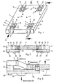
- Fig. 1 shows a preferred embodiment of the invention.
- a weighing platform 1 made of metal, for example made of the aluminum alloys 2o24-T351 or 7o75-T651, which are suitable for scales of small capacity.
- a suitable thickness for the platform 1 would be, for example, about 6 to 7 mm.
- Cast steel platforms would be used for larger capacity scales.
- Four groups 2, 3, 4 and 5 of holes 6 are completely through drilled through the platform 1. The arrangement of these hole groups in the platform and the spacing of the holes from one another can be different, as will be described further below.
- the holes are arranged substantially in the vicinity of a corner of the platform 1.
- a suitable distance between adjacent holes 6 and between the hole walls may be 8 to 9 mm.
- pairs of slots 7, 8, 9 and 10 are cut into the platform, e.g. by sawing so that each slot faces inward from an edge of the platform and connects two holes to the edge, thereby forming four beam elements 11, 12, 13 and 14 as an integral part of the platform structure.
- Strain gauges 15 and 16 are attached conventionally, e.g. by means of an adhesive connection on the beam element 11. These strain gauges are preferably arranged between the holes 6. In a similar manner, the strain gauges 17 and 18 are arranged on the beam element 12. The strain gauges 19 and 20 are attached to the beam element 13. Strain gauges 21 and 22 are attached to the beam structure 14.
- the dimensions of the holes and the thickness of the platform as well as the width of the slots depend on the desired capacity of the scale. These dimensions are selected in a professional manner with due regard to the weighing capacity and sensitivity.
- FIG. 2 shows the sectional view along the section line 2-2 in FIG. 1, as a result of which the beam elements 13 and 14 are illustrated without load.
- the cut surface extends through the holes 6 and the slots 9 and 10 , whereby the cut surface passes centrally and lengthwise through the corresponding slots.
- FIG. 2 shows a possible support structure tion including the feet 23, which are preferably made of a resilient material, such as rubber or the like, and are attached to the respective free end which is adjacent to the platform edge of the corresponding beam elements 13, 14.
- the connection is made by .ein Spacer 24 and a load bracket 25.
- Fig. 2 shows only two support structures 23, 24, 25, there are four of these structures, one in each corner.
- the outer end of each bracket 25 is fastened to the spacer 24 by means of connecting elements 26, for example screws or the like.
- the inner end of each bracket 25 extends far enough in relation to the platform 1 so that it cooperates with an overload limiter 27, which can be an adjustable screw in a threaded hole 27 ', so that the maximum bending of the corresponding beam elements is limited.
- the adjustment of the distance between the free inner end of each bracket 25 and the overload protection 27 is done in such a way that the spacer allows the beam structure to bend, which is just slightly above the nominal load for each corner.
- Fig. 3 shows the left corner of Fig. 2 on an enlarged scale under maximum load, so that the free end of the bracket 25 touches the overload stop 27 and the beam elements are bent into an approximately "S" shape.
- the strain gauge 21 is subjected to stretching and the strain gauge 22 is subjected to compression.
- the type of deflection, as shown in Fig. 3, optimizes the linearity characteristic of the beam and the associated strain gauges. The further functioning of the present balance is described below with reference to the circuit diagram according to FIG. 15.
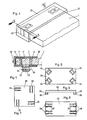
- the protective hood 28 which be at the ends of the platform 1 for protecting the beam elements, the strain gauges and the electrical connections is consolidated.
- the protective hood 28 may be attached to the platform 1 by means of the screws 29.
- the feet 23 of the support structures 23, 24, 25 extend through a hole 3o in the protective hood 28.
- the protective protective hoods can be made of extruded plastic or aluminum material and can, for example, have a rectangular, tubular cross section and be slotted on one side of the cross section to record platform 1 :.
- the ends 31 and 32 of the protective hood 28 are also closed in order to achieve the most complete protection possible.
- FIG. 6 shows a schematic plan view of a platform scale 33 in which the beam elements 34 are at an angle to the edge of the platform 33 with their longitudinal axis.
- the platform 35 is square in shape and the beam elements extend with their longitudinal axis perpendicular to the square sides into which the slots open and parallel to the next adjacent side. This arrangement of the beam elements can also be used with rectangular platforms.
- FIGS. 8 and 9 the bar elements are aligned as in FIG. 1, the feet 38 are connected to the relevant bar elements 37 by a spacer 39, which in turn form an integral part of the platform 40.
- This arrangement of the feet 38 avoids the use of the brackets 25 which are normally used to achieve the desired bending characteristic of the beam and optimize the linearity. While the omission of brackets 25 means a compromise on linearity, the overall behavior is quite appropriate for many applications.
- the platform 41 in a circular shape.
- the platform could also have a shape with any contour curves, for example an elliptical shape.
- the beam members 42 should preferably radially inwards and be mutually offset by 9 0 °.
- the beam elements 43 are arranged substantially centrally with respect to the sides of the rectangular or square platform 44.
- Figures 12 and 13 show modified versions of the overload stops.
- the foot 45 is connected to the free end of the beam element 46 by a bracket 47, also by an overload protection element 48 and a thin compensating plate 49.
- the length of the overload protection element is greater than the width of the beam element 46 and the two adjacent openings 5o together so that the free ends of the overload protection element 48 contact the platform 51 on both sides of the beam element 46 as soon as the load on the beam element causes the highest desired deflection.
- the permitted bending of the beam element 46 is determined by the thickness of the compensating plate 49. In this way, a possible overload is directed past the beam elements 46 and absorbed by the platform 51.
- each beam element is equipped with two strain gauges. As shown in Fig. 3, the strain gauges 21 and 22 are stretched or compressed as soon as the beam element in question bends under a load. Fig.
- FIG. 3 shows the bending of the beam 14 in an exaggerated manner for the purpose of simpler illustration.
- the clamp 25 will also bend somewhat, but this is not shown because it is not important for the invention.
- FIGS and 14 are connected to a Wheatstone bridge 59.
- the pairs of strain gauges on the beam elements 11 and 12 are connected to form a second Wheatstone bridge 6o.
- connection just described combines the strains measured by the individual strain gauges which are connected in a Wheatstone bridge, as well as the resistance changes in the strain gauges which are caused by such strains, so that a signal voltage arises as soon as the bridge is fed appropriately, which is a direct function of the sum of the loads on each of the two beam elements. Similarly, tension arises in the second Wheatstone bridge.
- the two Wheatstone bridge circuits 59 and 6 0 are connected in parallel to a common voltage supply 61.
- the output terminals of the bridges 59 and 6o are connected to common output terminals 62.
- an output signal is generated at the connections 62 which corresponds to the mean value of the output signals of the individual Wheatstone bridges 59 and 60.
- the output signal is thus essentially proportional to the sum of the loads which are detected by the individual bar elements with their strain gauges, which are combined and connected in the bridges 59 and 6 0 .
- This type of parallel addition by averaging the output signal from Wheatstone bridges is known in the art.
- strain gauges on beam members 13 and 14 and those on elements 11 and 12 were connected in the foregoing description, it would be equally satisfactory to connect the strain gauges on elements 12 and 13 and similarly the strain gauges on elements 11 and 14 as well . Similarly, it would also be satisfactory to connect the strain gauges on elements 11 and 13 and strain gauges on beam elements 12 and 14 together. Physical and geometrical considerations generally determine which choice of connection is advantageous in a particular construction.
- the function of the integrated scale structure is as follows. If the scale at point "A" is loaded centrally with the load or the weight to be measured, each bar element takes on an identical load speaking a quarter of the load placed.
- the strain gauges on each of the beam elements 11, 12, 13 and 14 measure the same strains and compressions.
- the resulting changes in resistance of the strain gauges in connection with the applied bridge supply voltage produce at the outputs of Wheatstone bridges 59 and 6o according to FIG. 15, which in turn arises from parallel addition as a result of the parallel connection of bridges 59 and 6o from FIG. 15. This signal is proportional to the load applied.
- the function of the scale with eccentric or eccentric loading can be described as follows. For example, if the load is applied at point "B" of Figure 1, the distribution of the load sensed by the beam elements will be significantly different. In the previous case of the central load, each of the beam elements was loaded with a quarter of the total load. In the case of the off-center load, the beam elements 13 and 14 will take up most of the applied load. The beam elements 13 and 14 and their associated strain gauges are only subjected to a very low load. For this reason, the changes in resistance and the resulting output signals, which are generated by the strain gauges on the beam elements 11 and 12, will be significantly smaller.
- the total height of the scale can be reduced considerably because the beam elements are arranged directly in the platform level.
- Another advantage of this embodiment of a scale is that the manufacturing costs are greatly reduced because drilling and sawing are extremely simple machining methods that can be carried out very simply using numerically controlled machine tools. Furthermore, economical production can be achieved by producing a large number of platforms at the same time. For example, five to ten plates can be processed simultaneously when they are stacked on top of one another so that the groups of holes can be drilled through all of the plates in one operation. As mentioned, the slots or openings can simply be sawn instead of milled, since the sensitivity of the beam elements is primarily determined by the hole size and the distance between adjacent holes and not by the width of the slots. The drilling is precisely controlled by numerically controlled drilling operations, so that the sensitivity of the beam elements can also be precisely achieved. In this way, the manufacturing costs of the scales presented are drastically reduced compared to the manufacturing costs of scales of the previously known type.
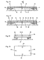
- FIG. 16 e.g. a rectangular housing 7o made of thin sheet metal is attached to the platform 71 by means of welded-on connecting pieces 73.
- the connecting pieces 73 are welded to the sheet metal housing 7o and nuts 74 are mounted on the supports 73, which pass through the platform 71 and fix the housing securely.
- a thin sheet metal housing like this can be used for scales with a low nominal load.
- the edges 75 of the housing 7o have a sufficient distance from the floor or table so that the bending of the beam elements as described above is not hindered.
- FIG. 17 shows a balance with a higher nominal load, for example for loads over approximately 45 kg. It has proven to be advantageous to fasten an intermediate plate 76 for load distribution to the platform 77 by means of screws 78, spacers 79 and nuts 8 0 .
- the intermediate plate 76 is chosen with an appropriate thickness so that it carries the applied load sufficiently well, without significant deflection.
- a rectangular housing 7o made of thinner sheet metal, as in FIG. 16, can be attached to the intermediate plate 76 by means of screws 81 or otherwise.
- FIGS. 16 and 17 illustrate the position or distribution of the load points 82, 83, 84, 85 between an intermediate plate 86 for load distribution and a platform 87 provided with strain gauges.
- the housing plate is not shown in FIG. 18.
- the intermediate plate 86 can with the platform as described above with reference to FIGS. 16 and 17, get connected.
- points 82, 83, 84, 85 for connecting the two plates depends on the arrangement of the beam elements on the plate or platform provided with strain gauges and depends on the respective length, width and thickness of the plate provided with strain gauges.
- the best alignment can be found easily by using simple spacers and moving them between the two plates until the most convenient location is found. The positions found in this way then apply to all scales of the same type.
Landscapes
- Physics & Mathematics (AREA)
- General Physics & Mathematics (AREA)
- Measurement Of Force In General (AREA)
Applications Claiming Priority (2)
| Application Number | Priority Date | Filing Date | Title |
|---|---|---|---|
| US06/105,157 US4261429A (en) | 1979-12-19 | 1979-12-19 | Unitized weighing apparatus and method for making such an apparatus |
| US105157 | 1979-12-19 |
Publications (2)
| Publication Number | Publication Date |
|---|---|
| EP0034656A1 true EP0034656A1 (fr) | 1981-09-02 |
| EP0034656B1 EP0034656B1 (fr) | 1983-06-29 |
Family
ID=22304353
Family Applications (1)
| Application Number | Title | Priority Date | Filing Date |
|---|---|---|---|
| EP80107686A Expired EP0034656B1 (fr) | 1979-12-19 | 1980-12-06 | Plateforme de pesage et procédé pour la fabrication de telles plates-formes de pesage |
Country Status (5)
| Country | Link |
|---|---|
| US (1) | US4261429A (fr) |
| EP (1) | EP0034656B1 (fr) |
| JP (1) | JPS56107127A (fr) |
| CA (1) | CA1148181A (fr) |
| DE (1) | DE3063995D1 (fr) |
Cited By (5)
| Publication number | Priority date | Publication date | Assignee | Title |
|---|---|---|---|---|
| EP0144494A1 (fr) * | 1983-11-08 | 1985-06-19 | Dr.-Ing. Ludwig Pietzsch GmbH & Co. | Balance pour mesurer la charge d'une roue |
| WO1985004711A1 (fr) * | 1984-04-13 | 1985-10-24 | Esselte Meto International Gmbh | Balance pese-personne |
| EP0310758B1 (fr) * | 1987-10-08 | 1992-09-09 | Robert Krups GmbH & Co. KG | Balance électromécanique |
| DE19811935A1 (de) * | 1998-03-19 | 1999-09-23 | Hbm Waegetechnik Gmbh | Kraftmeßelement |
| WO2014016150A1 (fr) | 2012-07-24 | 2014-01-30 | Siemens Aktiengesellschaft | Capteur dynamométrique |
Families Citing this family (28)
| Publication number | Priority date | Publication date | Assignee | Title |
|---|---|---|---|---|
| US4381826A (en) * | 1980-10-27 | 1983-05-03 | Mettler Instrumente Ag | Weighing scale of unitary construction |
| US4411327A (en) * | 1981-05-14 | 1983-10-25 | Hottinger Baldwin Measurements, Inc. | Apparatus for applying a load to a strain gage transducer beam |
| CA1183023A (fr) * | 1981-10-02 | 1985-02-26 | Maatschappij Van Berkel's Patent N.V. | Couteau de charge a protection contre les surcharges |
| AU562918B2 (en) * | 1982-08-17 | 1987-06-25 | Mettler-Toledo, Inc. | Compensated multi-load cell weighing scale |
| US4506746A (en) * | 1982-09-27 | 1985-03-26 | Hottinger Baldwin Measurements, Inc. | Gaged plate transducer weighing apparatus |
| JPS59162420A (ja) * | 1983-01-17 | 1984-09-13 | ホツテインガ−・バルトビン・メステヒニ−ク・ゲゼルシヤフト・ミツト・ベシユレンクテル・ハフツング | プラツトフオ−ム型秤 |
| EP0116170A3 (fr) * | 1983-01-17 | 1985-01-09 | Hottinger Baldwin Messtechnik Gmbh | Balance avec fléaux capteurs en forme de barre |
| CA1216312A (fr) * | 1983-05-19 | 1987-01-06 | Stephen A. Patoray | Appareil a couteaux de charge |
| US4515232A (en) * | 1983-11-07 | 1985-05-07 | Hottinger Baldwin Measurements, Inc. | Platform transducer beams |
| DE3562110D1 (en) * | 1984-05-18 | 1988-05-11 | Pietzsch Ludwig Gmbh & Co | Wheel load measuring device |
| JPH07104218B2 (ja) * | 1985-08-19 | 1995-11-13 | 株式会社ブリヂストン | 水平方向荷重測定装置 |
| US4949799A (en) * | 1986-02-03 | 1990-08-21 | Wernimont T August | Electronic weighing structure |
| US4898255A (en) * | 1989-01-17 | 1990-02-06 | Toledo Scale Corporation | Planar load cell |
| US5521334A (en) * | 1994-12-27 | 1996-05-28 | Pitney Bowes Inc. | Multiple overload protection for electronic scales |
| US5606516A (en) * | 1995-08-07 | 1997-02-25 | Fairbanks Scales Inc. | Digitally compensated hydraulic scale system |
| US6555767B1 (en) | 2000-08-22 | 2003-04-29 | Flintec, Inc. | Composite load cell |
| US6755087B2 (en) * | 2001-11-26 | 2004-06-29 | Interface, Inc. | Load cell having overload protection |
| WO2004055624A2 (fr) * | 2002-12-02 | 2004-07-01 | Conair Corporation | Systeme de controle de bascule et eponge |
| JP2004205410A (ja) * | 2002-12-26 | 2004-07-22 | Takata Corp | 荷重センサ及びシート重量計測装置 |
| US7048096B2 (en) * | 2003-12-08 | 2006-05-23 | Russell Ozechowski | Incremental braking apparatus and method of braking |
| US7737372B2 (en) * | 2007-06-13 | 2010-06-15 | Scaletron Industries, Ltd. | Leak and spill containment scale |
| DE102010060606A1 (de) | 2010-11-16 | 2012-05-16 | Siegfried Janner | Nahtlose Wagenkörper und Verfahren zur Herstellung |
| FR2980571B1 (fr) * | 2011-09-27 | 2014-05-16 | Seb Sa | Capteur de forces a butee integree et balance integrant un tel capteur |
| US9285281B1 (en) * | 2012-07-10 | 2016-03-15 | The United States Of America, As Represented By The Secretary Of The Army | Deflection plate for mobile dynamometer |
| ITTO20130093A1 (it) * | 2013-02-05 | 2014-08-06 | N B C Elettronica Group S R L | Bilancia elettronica |
| CN104526883B (zh) * | 2014-11-20 | 2017-02-22 | 徐州徐工施维英机械有限公司 | 添加剂计量装置、混凝土搅拌站及添加剂计量方法 |
| US10031037B1 (en) * | 2017-05-15 | 2018-07-24 | Goodrich Corporation | Stressroll load cells and methods for measuring effects of off-axis loads |
| DE102019008761A1 (de) * | 2019-12-14 | 2021-06-17 | PRlGNlTZ Mikrosystemtechnik GmbH | Drucksensor mit einer Membran mit Sensorchips mit Messbrücken mit Sensorelementen |
Citations (1)
| Publication number | Priority date | Publication date | Assignee | Title |
|---|---|---|---|---|
| DE2740668A1 (de) * | 1976-09-10 | 1978-03-16 | Nat Controls | Kraftmessdose |
Family Cites Families (11)
| Publication number | Priority date | Publication date | Assignee | Title |
|---|---|---|---|---|
| US3004231A (en) * | 1960-02-15 | 1961-10-10 | Baldwin Lima Hamilton Corp | Parallelogram beam type load cell |
| US3135112A (en) * | 1960-09-06 | 1964-06-02 | Baldwin Lima Hamilton Corp | Safety-load control of parallelogram type of load cell |
| US3439761A (en) * | 1966-10-17 | 1969-04-22 | Blh Electronics | Strain-gage transducer structures |
| US3966003A (en) * | 1974-10-15 | 1976-06-29 | Uniroyal Inc. | Weighing apparatus |
| US4009608A (en) * | 1975-01-20 | 1977-03-01 | Ormond Alfred N | Shear measuring flexure isolated load cells |
| US3968683A (en) * | 1975-06-02 | 1976-07-13 | Alfred Neuman Ormond | Electrical equalization of load element sensitivity |
| FR2331775A1 (fr) * | 1975-11-14 | 1977-06-10 | Sfim | Extensometre |
| DE2617987C2 (de) * | 1976-04-24 | 1985-06-20 | Elan-Schaltelemente Kurt Maecker Gmbh, 4040 Neuss | Meßvorrichtung mit Dehnungsmeßstreifen |
| US4146100A (en) * | 1978-03-24 | 1979-03-27 | Revere Corporation Of America | Leverless scale sensor |
| US4125168A (en) * | 1977-08-04 | 1978-11-14 | Ormond Alfred N | Load cells for flexure isolated electronic scale |
| US4150729A (en) * | 1978-05-09 | 1979-04-24 | Ormond A Newman | Strain gauge flexure isolated weighing scale |
-
1979
- 1979-12-19 US US06/105,157 patent/US4261429A/en not_active Expired - Lifetime
-
1980
- 1980-10-17 CA CA000362672A patent/CA1148181A/fr not_active Expired
- 1980-12-06 DE DE8080107686T patent/DE3063995D1/de not_active Expired
- 1980-12-06 EP EP80107686A patent/EP0034656B1/fr not_active Expired
- 1980-12-19 JP JP17915780A patent/JPS56107127A/ja active Pending
Patent Citations (1)
| Publication number | Priority date | Publication date | Assignee | Title |
|---|---|---|---|---|
| DE2740668A1 (de) * | 1976-09-10 | 1978-03-16 | Nat Controls | Kraftmessdose |
Cited By (8)
| Publication number | Priority date | Publication date | Assignee | Title |
|---|---|---|---|---|
| EP0144494A1 (fr) * | 1983-11-08 | 1985-06-19 | Dr.-Ing. Ludwig Pietzsch GmbH & Co. | Balance pour mesurer la charge d'une roue |
| WO1985004711A1 (fr) * | 1984-04-13 | 1985-10-24 | Esselte Meto International Gmbh | Balance pese-personne |
| EP0164839A3 (fr) * | 1984-04-13 | 1986-01-08 | Esselte Meto International Produktions Gmbh | Balances |
| EP0310758B1 (fr) * | 1987-10-08 | 1992-09-09 | Robert Krups GmbH & Co. KG | Balance électromécanique |
| DE19811935A1 (de) * | 1998-03-19 | 1999-09-23 | Hbm Waegetechnik Gmbh | Kraftmeßelement |
| WO2014016150A1 (fr) | 2012-07-24 | 2014-01-30 | Siemens Aktiengesellschaft | Capteur dynamométrique |
| DE102012212995A1 (de) | 2012-07-24 | 2014-02-13 | Siemens Aktiengesellschaft | Kraftaufnehmer |
| DE102012212995B4 (de) * | 2012-07-24 | 2016-03-03 | Siemens Aktiengesellschaft | Kraftaufnehmer |
Also Published As
| Publication number | Publication date |
|---|---|
| DE3063995D1 (en) | 1983-08-04 |
| US4261429A (en) | 1981-04-14 |
| EP0034656B1 (fr) | 1983-06-29 |
| CA1148181A (fr) | 1983-06-14 |
| JPS56107127A (en) | 1981-08-25 |
Similar Documents
| Publication | Publication Date | Title |
|---|---|---|
| EP0034656B1 (fr) | Plateforme de pesage et procédé pour la fabrication de telles plates-formes de pesage | |
| DE3439325C2 (de) | Lastdetektormechanismus | |
| DE69232155T2 (de) | Wägezelle mit einer Platte mit einer Öffnung und überbrückendem Dehnungssensor | |
| EP2153183B1 (fr) | Guidage de parallélogramme réglable, en particulier pour un instrument de mesure gravimétrique | |
| EP0012867B1 (fr) | Capteur extensomètrique par effect piézoélectrique | |
| EP0065176A2 (fr) | Dispositif pour appliquer une charge à un support sous forme d'une poutre | |
| EP2120023B1 (fr) | Cellule de pesage encapsulée dotée d'un réglage de la charge angulaire | |
| DE1774653A1 (de) | Vorrichtung zur elektrischen Messung von Lasten | |
| DE2900614A1 (de) | Dehnungsmesslastwandler | |
| DE2917169A1 (de) | Kraftmessdose und verfahren zu deren herstellung | |
| DE102016114193A1 (de) | Kraftmesseinrichtung zur mehrachsigen Erfassung einwirkender Kräfte und Momente | |
| EP0104557A2 (fr) | Balance | |
| DE102013012507B4 (de) | Stabförmiger Kraftaufnehmer mit vereinfachtem Abgleich | |
| DE1447995C3 (de) | Elektromechanischer Wandler mit einem Piezo-Widerstandselement | |
| DE2729150C2 (de) | Kraftaufnehmer | |
| DE60206339T2 (de) | Elektronische Waage | |
| EP1345015A2 (fr) | Elément de mesure de force pour dispositif de pesage et dispositif de pesage | |
| EP0483912B1 (fr) | Capteur de force de cisaillement de la forme d'un disque pour un élément de pesage | |
| CH353555A (de) | Kraftmesseinrichtung | |
| DE3634123C1 (en) | Power transducer | |
| DE2522131B2 (de) | Waage, insbesondere ladenwaage | |
| DE3119806C2 (fr) | ||
| DE3627382A1 (de) | Messanordnung zum erfassen von kraeften und momenten | |
| DE2129214A1 (de) | Messwertwandler, insbesondere fuer die kraftmessung | |
| EP0116170A2 (fr) | Balance avec fléaux capteurs en forme de barre |
Legal Events
| Date | Code | Title | Description |
|---|---|---|---|
| PUAI | Public reference made under article 153(3) epc to a published international application that has entered the european phase |
Free format text: ORIGINAL CODE: 0009012 |
|
| AK | Designated contracting states |
Designated state(s): AT BE CH DE FR GB IT LU NL SE |
|
| 17P | Request for examination filed |
Effective date: 19810630 |
|
| RBV | Designated contracting states (corrected) |
Designated state(s): BE DE FR GB NL SE |
|
| GRAA | (expected) grant |
Free format text: ORIGINAL CODE: 0009210 |
|
| AK | Designated contracting states |
Designated state(s): BE DE FR GB NL SE |
|
| REF | Corresponds to: |
Ref document number: 3063995 Country of ref document: DE Date of ref document: 19830804 |
|
| ET | Fr: translation filed | ||
| PLBE | No opposition filed within time limit |
Free format text: ORIGINAL CODE: 0009261 |
|
| STAA | Information on the status of an ep patent application or granted ep patent |
Free format text: STATUS: NO OPPOSITION FILED WITHIN TIME LIMIT |
|
| 26N | No opposition filed | ||
| PGFP | Annual fee paid to national office [announced via postgrant information from national office to epo] |
Ref country code: FR Payment date: 19841102 Year of fee payment: 5 |
|
| PGFP | Annual fee paid to national office [announced via postgrant information from national office to epo] |
Ref country code: NL Payment date: 19841114 Year of fee payment: 5 |
|
| PGFP | Annual fee paid to national office [announced via postgrant information from national office to epo] |
Ref country code: DE Payment date: 19841126 Year of fee payment: 5 |
|
| PGFP | Annual fee paid to national office [announced via postgrant information from national office to epo] |
Ref country code: SE Payment date: 19841231 Year of fee payment: 5 Ref country code: BE Payment date: 19841231 Year of fee payment: 5 |
|
| PG25 | Lapsed in a contracting state [announced via postgrant information from national office to epo] |
Ref country code: SE Effective date: 19851207 |
|
| PG25 | Lapsed in a contracting state [announced via postgrant information from national office to epo] |
Ref country code: BE Effective date: 19851231 |
|
| BERE | Be: lapsed |
Owner name: HOTTINGER BALDWIN MESSTECHNIK G.M.B.H. Effective date: 19851231 |
|
| PG25 | Lapsed in a contracting state [announced via postgrant information from national office to epo] |
Ref country code: NL Effective date: 19860701 |
|
| GBPC | Gb: european patent ceased through non-payment of renewal fee | ||
| NLV4 | Nl: lapsed or anulled due to non-payment of the annual fee | ||
| PG25 | Lapsed in a contracting state [announced via postgrant information from national office to epo] |
Ref country code: FR Free format text: LAPSE BECAUSE OF NON-PAYMENT OF DUE FEES Effective date: 19860829 |
|
| PG25 | Lapsed in a contracting state [announced via postgrant information from national office to epo] |
Ref country code: DE Effective date: 19860902 |
|
| REG | Reference to a national code |
Ref country code: FR Ref legal event code: ST |
|
| PG25 | Lapsed in a contracting state [announced via postgrant information from national office to epo] |
Ref country code: GB Effective date: 19881118 |
|
| EUG | Se: european patent has lapsed |
Ref document number: 80107686.0 Effective date: 19860902 |