EP0034657A1 - Dispositif pour la distribution dosée de produits pâteux - Google Patents
Dispositif pour la distribution dosée de produits pâteux Download PDFInfo
- Publication number
- EP0034657A1 EP0034657A1 EP80107714A EP80107714A EP0034657A1 EP 0034657 A1 EP0034657 A1 EP 0034657A1 EP 80107714 A EP80107714 A EP 80107714A EP 80107714 A EP80107714 A EP 80107714A EP 0034657 A1 EP0034657 A1 EP 0034657A1
- Authority
- EP
- European Patent Office
- Prior art keywords
- filling
- container
- paste
- shut
- tube
- Prior art date
- Legal status (The legal status is an assumption and is not a legal conclusion. Google has not performed a legal analysis and makes no representation as to the accuracy of the status listed.)
- Granted
Links
Images


Classifications
-
- B—PERFORMING OPERATIONS; TRANSPORTING
- B65—CONVEYING; PACKING; STORING; HANDLING THIN OR FILAMENTARY MATERIAL
- B65B—MACHINES, APPARATUS OR DEVICES FOR, OR METHODS OF, PACKAGING ARTICLES OR MATERIALS; UNPACKING
- B65B3/00—Packaging plastic material, semiliquids, liquids or mixed solids and liquids, in individual containers or receptacles, e.g. bags, sacks, boxes, cartons, cans, or jars
- B65B3/26—Methods or devices for controlling the quantity of the material fed or filled
- B65B3/30—Methods or devices for controlling the quantity of the material fed or filled by volumetric measurement
- B65B3/32—Methods or devices for controlling the quantity of the material fed or filled by volumetric measurement by pistons co-operating with measuring chambers
Definitions
- the invention relates to a device for the metered filling of a viscous paste from a storage container into a cylindrical filling container with a filling tube which can be immersed in the filling container and with a shut-off valve, by means of which the paste is pressed from an intermediate container into the filling container during the filling process, the mouth of the filling container being fixed Filling pipe is pulled out of the filling container according to the rising level of the paste in the filling container, and with a filling line with a shut-off valve connecting the storage container to the intermediate container.
- the intermediate container is designed there as a measuring cylinder with a piston such that the inside diameter of the measuring cylinder corresponds to the inside diameter of the filling container concerned.
- the lower end of the filling tube is pulled upwards in accordance with the level of the filled paste in the filling container, so that the paste is filled without air pockets.
- the device has proven itself in and of itself.
- there are relatively high pressures required to fill the measuring cylinder because this has to be filled via a three-way valve.
- the measuring cylinder with the piston and other associated components must be replaced if the paste is to be filled into a filling container with a different cross section.
- the invention is therefore based on the object while maintaining the principle that during the filling process the mouth of the filling tube corresponds to the level of the filled paste in the filling container. follows to further simplify the known device and in particular to avoid throttling points during the filling process into the intermediate container as well as sealing problems and to simplify adaptation of the device to filling containers with a different cross section.
- the object is achieved according to the invention in that the intermediate container is fixed, that the filling pipe with its shut-off valve is movable and exchangeable relative to and into and out of the intermediate container, and that the cross-sectional area of the filling pipe is equal to that clear cross-sectional area of the filling container.
- the intermediate container is now filled through the additional filling line with shut-off valve, the cross-sections of which can be selected as required. It is only necessary to ensure a good seal between the sliding filling tube and the intermediate container. Because the cross-sectional area of the filling tube is equal to the clear cross-sectional area of the filling container, the level of the paste filled into the filling container follows the lower mouth of the filling container when the filling tube is pulled into the intermediate container. To change to filling containers with a different diameter, only the filling tube has to be replaced, i.e. the filling pipe only needs to be pulled out of the intermediate container.
- the lower end of the filling pipe stands on a recess of a plate connected to a piston-cylinder unit.
- a plate connected to a piston-cylinder unit.
- the piston-cylinder unit and the plate is also inserted into the intermediate container during the filling process.
- the cross-sectional area of the filling tube When changing to filling containers with different dimensions, the cross-sectional area of the filling tube must be equal to the clear cross-sectional area of the filling container, as mentioned.
- the filling pipe can be moved in a sealing manner in an annular flange which is screwed onto the intermediate container in an exchangeable manner. It is therefore only necessary to replace the assembly consisting of the filling pipe with an annular flange by a new assembly with corresponding dimensions.
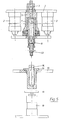
- the device shown has a frame-fixed upper plate 1, with which two piston-cylinder units 2 are connected.
- an upper ball valve 3 is seated on the plate 1 and is inserted into a filling line 4.
- the filling line is led to an intermediate container 5, which is also arranged fixed to the frame and which is designed as a cylinder, which is closed on its underside by an annular flange 6.
- a filling pipe 7 is inserted sealingly into the opening of the ring flange.
- the ring flange is fastened to the intermediate container 5 in an easily replaceable manner by means of a union nut 8.
- a plate 9 is firmly connected to the pistons of the units 2 and can be raised or lowered in the direction of the double arrow 10.
- the plate 9 has a recess 11 adapted to the filling tube 7, into which the lower end of the filling tube is inserted.
- the plate has a bore tapering downwards, which is guided to a lower ball valve 12. This in turn continues down to a metering tube 13.
- a filling container 14 to be filled with a paste for example a cartridge or a tube, is inserted into a receiving piece 15 from above.
- the receiving piece is in turn inserted into a hole in a rotary table 16 with the interposition of a chuck 17.
- the rotary table has several such receptacles for filling containers on the same circular arc.
- a plate 18 which can be raised by a pneumatic lifting cylinder 19.
- the operation of the device is as follows: At the beginning of a filling cycle, the filling tube 7 is completely drawn into the intermediate container 5, by a corresponding actuation of the piston-cylinder units 2.
- the intermediate container 5, the filling line 4 and also the filling tube 7 are filled with a viscous paste with the metering tube 13, as indicated in the drawing. Both taps 3, 12 are closed.
- the filling container 14 is in a lower, lowered position (see FIG. 1).
- the upper ball valve 3 is now opened and paste is pressed into the intermediate container 5 via a storage container (not shown) and the filling line 4, the lower ball valve 12 remaining closed.
- This filling pressure causes the plate 9 to move downward into shown position moves, the piston-cylinder units 2 have been relieved accordingly to be able to participate in this movement.
- the filling container 14 was raised by actuating the lifting cylinder 19. With the lowering of the plate 9, the filling pipe 7 was also extended. The situation according to FIG. 2 has now been reached.
- FIG. 4 shows the filled filling container 14, which now only needs to be closed.
- the stroke cylinder 19 is actuated again, which lowers the filled filling container 14 downwards, as shown in FIG. 5.
- the lower ball valve 12 is also closed after the upper ball valve 3 has already been closed in the step according to FIG. 3.
- the state according to FIG. 5 has been reached and the cycle can begin again after a new filling container 14 has advanced under the mouth of the metering tube 13.
- the cross-sectional area of the filling tube 7 is equal to the clear cross-sectional area of the filling container 14. Because both the filling tube and the filling container are circular cylindrical, the outside diameter of the filling tube 7 is also equal to the inside diameter of the filling container 14.
- the diameter of the bore can be freely selected if the condition specified above is fulfilled.
- the diameter of the bore of the filling tube 7 is preferably chosen to be as large as possible because the flow resistance in the bore is then small. This is a major advantage of the new device.
- the novel device manages with a pressure of 70 to 80 bar at a cycle of 15 per minute, compared to a pressure of 180 bar with the same cycle in the device according to the aforementioned DE-OS 2 610 396. Der So pressure can be more than halved. This is due to the larger cross-sections and the shorter distances that the paste has to travel in the device. The new device therefore works more gently.
Landscapes
- Engineering & Computer Science (AREA)
- Mechanical Engineering (AREA)
- Basic Packing Technique (AREA)
- Feeding, Discharge, Calcimining, Fusing, And Gas-Generation Devices (AREA)
- Coating Apparatus (AREA)
Priority Applications (1)
| Application Number | Priority Date | Filing Date | Title |
|---|---|---|---|
| AT80107714T ATE3395T1 (de) | 1980-02-26 | 1980-12-08 | Vorrichtung zum dosierten abfuellen einer zaehviskosen paste. |
Applications Claiming Priority (2)
| Application Number | Priority Date | Filing Date | Title |
|---|---|---|---|
| DE3007069A DE3007069C2 (de) | 1980-02-26 | 1980-02-26 | Vorrichtung zum dosierten Abfüllen einer zähviskosen Paste |
| DE3007069 | 1980-02-26 |
Publications (2)
| Publication Number | Publication Date |
|---|---|
| EP0034657A1 true EP0034657A1 (fr) | 1981-09-02 |
| EP0034657B1 EP0034657B1 (fr) | 1983-05-18 |
Family
ID=6095535
Family Applications (1)
| Application Number | Title | Priority Date | Filing Date |
|---|---|---|---|
| EP80107714A Expired EP0034657B1 (fr) | 1980-02-26 | 1980-12-08 | Dispositif pour la distribution dosée de produits pâteux |
Country Status (3)
| Country | Link |
|---|---|
| EP (1) | EP0034657B1 (fr) |
| AT (1) | ATE3395T1 (fr) |
| DE (2) | DE3007069C2 (fr) |
Cited By (2)
| Publication number | Priority date | Publication date | Assignee | Title |
|---|---|---|---|---|
| FR2639849A1 (fr) * | 1988-12-01 | 1990-06-08 | Mathou Jean Pierre | Dispositif de distribution de colle |
| WO2003104652A1 (fr) * | 2002-06-06 | 2003-12-18 | Bs & B Safety Systems Limited | Systeme de pompage a unite piston-cylindre remplaçable |
Citations (1)
| Publication number | Priority date | Publication date | Assignee | Title |
|---|---|---|---|---|
| DE2610396A1 (de) * | 1976-03-12 | 1977-09-22 | Ge Halin Abfuellmaschinenfabri | Vorrichtung zum dosierten abfuellen einer paste |
Family Cites Families (3)
| Publication number | Priority date | Publication date | Assignee | Title |
|---|---|---|---|---|
| FR88122E (fr) * | 1965-03-29 | 1966-04-15 | Remy & Cie E P | Dispositif de dosage pour produits liquides ou semi-fluides et installation utilisant un tel dispositif |
| DE2438796C2 (de) * | 1974-08-13 | 1983-02-24 | Josef 4422 Ahaus Finnah | Vorrichtung zum portionsweisen Abfüllen von flüssigem oder pastösem Füllgut in Behältnisse |
| DE2551331A1 (de) * | 1975-11-15 | 1977-05-26 | Bayer Ag | Hubabhaengige differenzdosiereinrichtung |
-
1980
- 1980-02-26 DE DE3007069A patent/DE3007069C2/de not_active Expired
- 1980-12-08 AT AT80107714T patent/ATE3395T1/de active
- 1980-12-08 DE DE8080107714T patent/DE3063377D1/de not_active Expired
- 1980-12-08 EP EP80107714A patent/EP0034657B1/fr not_active Expired
Patent Citations (1)
| Publication number | Priority date | Publication date | Assignee | Title |
|---|---|---|---|---|
| DE2610396A1 (de) * | 1976-03-12 | 1977-09-22 | Ge Halin Abfuellmaschinenfabri | Vorrichtung zum dosierten abfuellen einer paste |
Cited By (3)
| Publication number | Priority date | Publication date | Assignee | Title |
|---|---|---|---|---|
| FR2639849A1 (fr) * | 1988-12-01 | 1990-06-08 | Mathou Jean Pierre | Dispositif de distribution de colle |
| WO2003104652A1 (fr) * | 2002-06-06 | 2003-12-18 | Bs & B Safety Systems Limited | Systeme de pompage a unite piston-cylindre remplaçable |
| US7284961B2 (en) | 2002-06-06 | 2007-10-23 | Bs&B Safety Systems, Ltd. | Pumping system, replacement kit including piston and/or cylinder, and method for pumping system maintenance |
Also Published As
| Publication number | Publication date |
|---|---|
| DE3007069A1 (de) | 1981-09-03 |
| DE3063377D1 (en) | 1983-07-07 |
| ATE3395T1 (de) | 1983-06-15 |
| DE3007069C2 (de) | 1982-07-22 |
| EP0034657B1 (fr) | 1983-05-18 |
Similar Documents
| Publication | Publication Date | Title |
|---|---|---|
| EP0536505B1 (fr) | Procédé et dispositif pour remplir un récipient avec un liquide | |
| DE3926591A1 (de) | Vorrichtung zum fuellen von behaeltern | |
| DE2345731C3 (de) | Vorrichtung zur Prüfung von Hohlkörpern, insbesondere Glasflaschen | |
| DE2340613A1 (de) | Verfahren und einrichtung zum fuellen von behaeltern mit einer gas enthaltenden fluessigkeit | |
| DE2002060A1 (de) | Fuellrohrloses Fuellelement fuer Gegendruck-Fuellmaschinen in Ein- oder Mehrkammer-Bauweise | |
| EP0564626B1 (fr) | Dispositif de nettoyage et de vidange de conduits pour boissons dans des systemes de soutirage | |
| DE3325338A1 (de) | Fuelleinrichtung fuer stillgetraenke | |
| DE2626055A1 (de) | Vorrichtung zum fuellen von faessern | |
| EP0034657B1 (fr) | Dispositif pour la distribution dosée de produits pâteux | |
| DE29513213U1 (de) | Zapfkopf zur Entnahme einer unter Gasdruck stehenden Flüssigkeit, z.B. Bier | |
| DE3307245C2 (de) | Verfahren zum Befüllen eines Behälters mit einem unter Druck stehenden Medium | |
| DE3742418A1 (de) | Vorrichtung zum einstanzen von oesen in textil-, kunststoffplane oder dgl. | |
| DE973946C (de) | Automatische Abfuellvorrichtung fuer gashaltige Fluessigkeiten | |
| EP4007736A1 (fr) | Élément de remplissage destiné au remplissage de bouteilles ou de récipients analogues avec un produit de remplissage liquide et machine de remplissage équipée d'éléments de remplissage de ce type | |
| DE2933622A1 (de) | Maschine zum reinigen und fuellen von behaeltern | |
| DE3933754C2 (fr) | ||
| DE2657671A1 (de) | Blas- und fuellvorrichtung fuer maschinen zum formen, abfuellen und verschliessen oder verschweissen von hohlkoerpern aus thermoplasten | |
| DE2848604C2 (de) | Vorrichtung zum Abfüllen von Getränken | |
| DE2628825B2 (de) | Vorrichtung zum Eintreiben eines Stopfens in das Zapfloch eines Fasses | |
| DE3515769A1 (de) | Abfuellvorrichtung fuer bier oder dergleichen fluessigkeiten | |
| DE177471C (fr) | ||
| DE2462210C3 (de) | Füllkopf zum Füllen von Druckzerstäuberpackungen | |
| DE1138657B (de) | Vorrichtung zum Ausschenken von Fluessigkeiten | |
| DE3725609A1 (de) | Fuellelement fuer behaelterfuellmaschine | |
| DE303461C (fr) |
Legal Events
| Date | Code | Title | Description |
|---|---|---|---|
| PUAI | Public reference made under article 153(3) epc to a published international application that has entered the european phase |
Free format text: ORIGINAL CODE: 0009012 |
|
| AK | Designated contracting states |
Designated state(s): AT BE CH DE FR GB IT NL SE |
|
| 17P | Request for examination filed |
Effective date: 19810917 |
|
| ITF | It: translation for a ep patent filed | ||
| GRAA | (expected) grant |
Free format text: ORIGINAL CODE: 0009210 |
|
| AK | Designated contracting states |
Designated state(s): AT BE CH DE FR GB IT LI NL SE |
|
| REF | Corresponds to: |
Ref document number: 3395 Country of ref document: AT Date of ref document: 19830615 Kind code of ref document: T |
|
| ET | Fr: translation filed | ||
| REF | Corresponds to: |
Ref document number: 3063377 Country of ref document: DE Date of ref document: 19830707 |
|
| PLBE | No opposition filed within time limit |
Free format text: ORIGINAL CODE: 0009261 |
|
| STAA | Information on the status of an ep patent application or granted ep patent |
Free format text: STATUS: NO OPPOSITION FILED WITHIN TIME LIMIT |
|
| 26N | No opposition filed | ||
| ITTA | It: last paid annual fee | ||
| PGFP | Annual fee paid to national office [announced via postgrant information from national office to epo] |
Ref country code: BE Payment date: 19941003 Year of fee payment: 15 |
|
| PGFP | Annual fee paid to national office [announced via postgrant information from national office to epo] |
Ref country code: AT Payment date: 19941013 Year of fee payment: 15 |
|
| PGFP | Annual fee paid to national office [announced via postgrant information from national office to epo] |
Ref country code: CH Payment date: 19941017 Year of fee payment: 15 |
|
| PGFP | Annual fee paid to national office [announced via postgrant information from national office to epo] |
Ref country code: FR Payment date: 19941028 Year of fee payment: 15 |
|
| PGFP | Annual fee paid to national office [announced via postgrant information from national office to epo] |
Ref country code: GB Payment date: 19941031 Year of fee payment: 15 |
|
| PGFP | Annual fee paid to national office [announced via postgrant information from national office to epo] |
Ref country code: SE Payment date: 19941102 Year of fee payment: 15 |
|
| PGFP | Annual fee paid to national office [announced via postgrant information from national office to epo] |
Ref country code: NL Payment date: 19941231 Year of fee payment: 15 |
|
| EAL | Se: european patent in force in sweden |
Ref document number: 80107714.0 |
|
| PG25 | Lapsed in a contracting state [announced via postgrant information from national office to epo] |
Ref country code: GB Effective date: 19951208 Ref country code: AT Effective date: 19951208 |
|
| PG25 | Lapsed in a contracting state [announced via postgrant information from national office to epo] |
Ref country code: SE Effective date: 19951209 |
|
| PG25 | Lapsed in a contracting state [announced via postgrant information from national office to epo] |
Ref country code: LI Effective date: 19951231 Ref country code: CH Effective date: 19951231 Ref country code: BE Effective date: 19951231 |
|
| BERE | Be: lapsed |
Owner name: GEHALIN MASCHINENFABRIK G.M.B.H. Effective date: 19951231 |
|
| PG25 | Lapsed in a contracting state [announced via postgrant information from national office to epo] |
Ref country code: NL Effective date: 19960701 |
|
| GBPC | Gb: european patent ceased through non-payment of renewal fee |
Effective date: 19951208 |
|
| REG | Reference to a national code |
Ref country code: CH Ref legal event code: PL |
|
| PG25 | Lapsed in a contracting state [announced via postgrant information from national office to epo] |
Ref country code: FR Effective date: 19960830 |
|
| NLV4 | Nl: lapsed or anulled due to non-payment of the annual fee |
Effective date: 19960701 |
|
| REG | Reference to a national code |
Ref country code: FR Ref legal event code: ST |
|
| PGFP | Annual fee paid to national office [announced via postgrant information from national office to epo] |
Ref country code: DE Payment date: 20000114 Year of fee payment: 20 |