EP0034657A1 - Vorrichtung zum dosierten Abfüllen einer zähviskosen Paste - Google Patents
Vorrichtung zum dosierten Abfüllen einer zähviskosen Paste Download PDFInfo
- Publication number
- EP0034657A1 EP0034657A1 EP80107714A EP80107714A EP0034657A1 EP 0034657 A1 EP0034657 A1 EP 0034657A1 EP 80107714 A EP80107714 A EP 80107714A EP 80107714 A EP80107714 A EP 80107714A EP 0034657 A1 EP0034657 A1 EP 0034657A1
- Authority
- EP
- European Patent Office
- Prior art keywords
- filling
- container
- paste
- shut
- tube
- Prior art date
- Legal status (The legal status is an assumption and is not a legal conclusion. Google has not performed a legal analysis and makes no representation as to the accuracy of the status listed.)
- Granted
Links
Images


Classifications
-
- B—PERFORMING OPERATIONS; TRANSPORTING
- B65—CONVEYING; PACKING; STORING; HANDLING THIN OR FILAMENTARY MATERIAL
- B65B—MACHINES, APPARATUS OR DEVICES FOR, OR METHODS OF, PACKAGING ARTICLES OR MATERIALS; UNPACKING
- B65B3/00—Packaging plastic material, semiliquids, liquids or mixed solids and liquids, in individual containers or receptacles, e.g. bags, sacks, boxes, cartons, cans, or jars
- B65B3/26—Methods or devices for controlling the quantity of the material fed or filled
- B65B3/30—Methods or devices for controlling the quantity of the material fed or filled by volumetric measurement
- B65B3/32—Methods or devices for controlling the quantity of the material fed or filled by volumetric measurement by pistons co-operating with measuring chambers
Definitions
- the invention relates to a device for the metered filling of a viscous paste from a storage container into a cylindrical filling container with a filling tube which can be immersed in the filling container and with a shut-off valve, by means of which the paste is pressed from an intermediate container into the filling container during the filling process, the mouth of the filling container being fixed Filling pipe is pulled out of the filling container according to the rising level of the paste in the filling container, and with a filling line with a shut-off valve connecting the storage container to the intermediate container.
- the intermediate container is designed there as a measuring cylinder with a piston such that the inside diameter of the measuring cylinder corresponds to the inside diameter of the filling container concerned.
- the lower end of the filling tube is pulled upwards in accordance with the level of the filled paste in the filling container, so that the paste is filled without air pockets.
- the device has proven itself in and of itself.
- there are relatively high pressures required to fill the measuring cylinder because this has to be filled via a three-way valve.
- the measuring cylinder with the piston and other associated components must be replaced if the paste is to be filled into a filling container with a different cross section.
- the invention is therefore based on the object while maintaining the principle that during the filling process the mouth of the filling tube corresponds to the level of the filled paste in the filling container. follows to further simplify the known device and in particular to avoid throttling points during the filling process into the intermediate container as well as sealing problems and to simplify adaptation of the device to filling containers with a different cross section.
- the object is achieved according to the invention in that the intermediate container is fixed, that the filling pipe with its shut-off valve is movable and exchangeable relative to and into and out of the intermediate container, and that the cross-sectional area of the filling pipe is equal to that clear cross-sectional area of the filling container.
- the intermediate container is now filled through the additional filling line with shut-off valve, the cross-sections of which can be selected as required. It is only necessary to ensure a good seal between the sliding filling tube and the intermediate container. Because the cross-sectional area of the filling tube is equal to the clear cross-sectional area of the filling container, the level of the paste filled into the filling container follows the lower mouth of the filling container when the filling tube is pulled into the intermediate container. To change to filling containers with a different diameter, only the filling tube has to be replaced, i.e. the filling pipe only needs to be pulled out of the intermediate container.
- the lower end of the filling pipe stands on a recess of a plate connected to a piston-cylinder unit.
- a plate connected to a piston-cylinder unit.
- the piston-cylinder unit and the plate is also inserted into the intermediate container during the filling process.
- the cross-sectional area of the filling tube When changing to filling containers with different dimensions, the cross-sectional area of the filling tube must be equal to the clear cross-sectional area of the filling container, as mentioned.
- the filling pipe can be moved in a sealing manner in an annular flange which is screwed onto the intermediate container in an exchangeable manner. It is therefore only necessary to replace the assembly consisting of the filling pipe with an annular flange by a new assembly with corresponding dimensions.
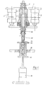
- the device shown has a frame-fixed upper plate 1, with which two piston-cylinder units 2 are connected.
- an upper ball valve 3 is seated on the plate 1 and is inserted into a filling line 4.
- the filling line is led to an intermediate container 5, which is also arranged fixed to the frame and which is designed as a cylinder, which is closed on its underside by an annular flange 6.
- a filling pipe 7 is inserted sealingly into the opening of the ring flange.
- the ring flange is fastened to the intermediate container 5 in an easily replaceable manner by means of a union nut 8.
- a plate 9 is firmly connected to the pistons of the units 2 and can be raised or lowered in the direction of the double arrow 10.
- the plate 9 has a recess 11 adapted to the filling tube 7, into which the lower end of the filling tube is inserted.
- the plate has a bore tapering downwards, which is guided to a lower ball valve 12. This in turn continues down to a metering tube 13.
- a filling container 14 to be filled with a paste for example a cartridge or a tube, is inserted into a receiving piece 15 from above.
- the receiving piece is in turn inserted into a hole in a rotary table 16 with the interposition of a chuck 17.
- the rotary table has several such receptacles for filling containers on the same circular arc.
- a plate 18 which can be raised by a pneumatic lifting cylinder 19.
- the operation of the device is as follows: At the beginning of a filling cycle, the filling tube 7 is completely drawn into the intermediate container 5, by a corresponding actuation of the piston-cylinder units 2.
- the intermediate container 5, the filling line 4 and also the filling tube 7 are filled with a viscous paste with the metering tube 13, as indicated in the drawing. Both taps 3, 12 are closed.
- the filling container 14 is in a lower, lowered position (see FIG. 1).
- the upper ball valve 3 is now opened and paste is pressed into the intermediate container 5 via a storage container (not shown) and the filling line 4, the lower ball valve 12 remaining closed.
- This filling pressure causes the plate 9 to move downward into shown position moves, the piston-cylinder units 2 have been relieved accordingly to be able to participate in this movement.
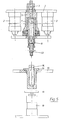
- the filling container 14 was raised by actuating the lifting cylinder 19. With the lowering of the plate 9, the filling pipe 7 was also extended. The situation according to FIG. 2 has now been reached.
- FIG. 4 shows the filled filling container 14, which now only needs to be closed.
- the stroke cylinder 19 is actuated again, which lowers the filled filling container 14 downwards, as shown in FIG. 5.
- the lower ball valve 12 is also closed after the upper ball valve 3 has already been closed in the step according to FIG. 3.
- the state according to FIG. 5 has been reached and the cycle can begin again after a new filling container 14 has advanced under the mouth of the metering tube 13.
- the cross-sectional area of the filling tube 7 is equal to the clear cross-sectional area of the filling container 14. Because both the filling tube and the filling container are circular cylindrical, the outside diameter of the filling tube 7 is also equal to the inside diameter of the filling container 14.
- the diameter of the bore can be freely selected if the condition specified above is fulfilled.
- the diameter of the bore of the filling tube 7 is preferably chosen to be as large as possible because the flow resistance in the bore is then small. This is a major advantage of the new device.
- the novel device manages with a pressure of 70 to 80 bar at a cycle of 15 per minute, compared to a pressure of 180 bar with the same cycle in the device according to the aforementioned DE-OS 2 610 396. Der So pressure can be more than halved. This is due to the larger cross-sections and the shorter distances that the paste has to travel in the device. The new device therefore works more gently.
Landscapes
- Engineering & Computer Science (AREA)
- Mechanical Engineering (AREA)
- Basic Packing Technique (AREA)
- Feeding, Discharge, Calcimining, Fusing, And Gas-Generation Devices (AREA)
- Coating Apparatus (AREA)
Abstract
Description
- Die Erfindung betrifft eine Vorrichtung zum dosierten Abfüllen einer zähviskosen Paste aus einem Vorratsbehälter in einen zylindrischen Abfüllbehälter mit einem in den Abfüllbehälter eintauchbaren Abfüllrohr mit Absperrhahn, durch das die Paste beim Abfüllvorgang aus einem Zwischenbehälter in den Abfüllbehälter gedrückt wird, wobei bei feststehendem Abfüllbehälter die Mündung des Abfüllrohres dem ansteigenden Niveau der Paste im Abfüllbehälter entsprechend aus dem Abfüllbehälter herausgezogen wird, und mit einer den Vorratsbehälter mit dem Zwischenbehälter verbindenen Einfülleitung mit Absperrhahn.
- Eine derartige Vorrichtung beschreibt die DE-OS 2 610 396 der Anmelderin. Um zu erreichen, daß die über diese Vorrichtung in den jeweiligen Abfüllbehälter ( Kartusche oder dergleichen) abgefüllte Paste ohne Lufteinschlüsse abgefüllt wird, ist der Zwischenbehälter dort als Meßzylinder mit Kolben derart ausgebildet, daß der Innendurchmesser des Meßzylinders dem Innendurchmesser des betreffenden Abfüllbehälters entspricht. Beim Abfüllvorgang wird somit das untere Ende des Abfüllrohres entsprechend dem Niveau der abgefüllten Paste im Abfüllbehälter nach oben herausgezogen, so daß die Paste ohne Lufteinschlüsse abgefüllt wird. Die Vorrichtung hat sich an und für sich bewährt. Es sind dort jedoch zum Füllen des Meßzylinders verhältnismäßig hohe Drücke erforderlich, weil dieser nämlich über - einen Drei-Wege-Hahn befüllt werden muß. Außerdem können sich Abdichtprobleme am Hahn bzw. am oberen Ende des Meßzylinders ergeben. Fernerhin muß der Meßzylinder mit Kolben und weiteren, zugehörigen Bauteilen ausgewechselt werden, wenn die Paste in Abfüllbehälter mit einem anderen Querschnitt abgefüllt werden soll.
- Der Erfindung liegt daher die Aufgabe zugrunde, unter Beibehaltung des Prinzips, wonach beim Abfüllvorgang die Mündung des Abfüllrohres dem Niveau der abgefüllten Paste im Abfüllbehälter. folgt, die bekannte Vorrichtung weiterhin zu vereinfachen und insbesondere Drosselstellen beim Einfüllvorgang in den Zwischenbehälter sowie Dichtungsprobleme zu vermeiden und eine Anpassung der Vorrichtung an Abfüllbehälter mit anderem Querschnitt zu vereinfachen.
- Ausgehend von einer Vorrichtung der eingangs genannten Art wird die Aufgabe erfindungsgemäß dadurch gelöst, daß der Zwischenbehälter feststehend ist, daß das Abfüllrohr mit seinem Absperrhahn relativ zum Zwischenbehälter und in diesen hinein bzw. heraus beweglich und auswechselbar ist, und daß die Querschnittsfläche des Abfüllrohres gleich der lichten Querschnittsfläche des Abfüllbehälters ist.
- Die Befüllung des Zwischenbehälters erfolgt jetzt durch die zusätzlich Einfülleitung mit Absperrhahn, deren Querschnitte beliebig gewählt werden können. Es muß lediglich für eine gute Dichtung zwischen dem verschiebbaren Abfüllrohr und dem Zwischenbehälter gesorgt werden. Weil die Querschnittsfläche des Abfüllrohrs gleich der lichten Querschnittsfläche des Abfüllbehälters ist, folgt das Niveau der in den Abfüllbehälter eingefüllten Paste beim Einziehvorgang des Abfüllrohres in den Zwischenbehälter der unteren Mündung des Abfüllbehälters. Zum Übergang auf Abfüllbehälter mit einem anderen Durchmesser muß lediglich das Abfüllrohr ausgewechselt werden, d.h. das Abfüllrohr braucht lediglich aus dem Zwischenbehälter herausgezogen zu werden.
- Um das Abfüllrohr leicht auswechseln zu können, wird es bevorzugt, wenn das Abfüllrohr mit seinem unteren Ende auf einer Ausnehmung einer mit einer Kolben-Zylinder-Einheit verbundenen Platte aufsteht. Über die Kolben-Zylinder-Einheit und die Platte wird außerdem das Abfüllrohr beim Abfüllvorgang in den Zwischenbehälter eingeschoben.
- Beim Übergang auf Abfüllbehälter mit anderen Abmessungen muß, wie erwähnt, die Querschnittsfläche des Abfüllrohres gleich der lichten Querschnittsfläche des Abfüllbehälters sein. Um dies zu erreichen, ist das Abfüllrohr in einem Ringflansch dichtend verschiebbar, der auswechselbar an den Zwischenbehälter angeschraubt ist. Es braucht also lediglich die Baueinheit bestehend aus dem Abfüllrohr mit Ringflansch durch eine neue Baueinheit mit entsprechenden Dimensionen ersetzt zu werden.
- Die Erfindung wird im folgenden anhand eines Ausführungsbeispiels näher erläutert, aus dem sich weitere wichtige Merkmale ergeben. Die Figuren zeigen in einem Längsschnitt die Aufeinanderfolge eines Abfüllzyklus' zum Befüllen einer Kartusche, und zwar
- Fig. 1 den Beginn des Abfüllvorganges,
- Fig. 2
- bis 4 die Zwischenstationen des Abfüllvorganges und
- Fig. 5 das Ende dieses Abfüllzyklus'.
- Die gezeigte Vorrichtung besitzt eine rahmenfeste obere Platte 1, mit der zwei Kolben-Zylinder-Einheiten 2 verbunden sind. Außerdem sitzt auf der Platte 1 ein oberer Kugelhahn 3 auf, der in eine Einfülleitung 4 eingesetzt ist. Die Einfülleitung ist zu einem Zwischenbehälter 5 geführt, der ebenfalls rahmenfest angeordnet ist und der als Zylinder ausgebildet ist, der an seiner Unterseite von einem Ringflansch 6 abgeschlossen ist. In die Öffnung des Ringflansches ist dichtend ein Abfüllrohr 7 eingesetzt. Der Ringflansch ist über eine Überwurfmutter 8 leicht auswechselbar am Zwischenbehälter 5 befestigt.
- Mit den Kolben der Einheiten 2 ist eine Platte 9 fest verbunden, die in Richtung des Doppelpfeiles 10 angehoben bzw. abgesenkt werden kann. Mittig hat die Platte 9 eine dem Abfüllrohr 7 angepaßte Ausnehmung 11, in die das Abfüllrohr mit seinem unteren Ende eingesetzt ist. Außerdem hat die Platte eine sich nach unten verjüngende Bohrung, die zu einem unteren Kugelhahn 12 geführt ist. Dieser wiederum setzt sich nach unten zu einem Dosierrohr 13 fort.
- Ein mit einer Paste zu befüllender Abfüllbehälter 14, beispielsweise eine Kartusche oder eine Tube, ist in ein Aufnahmestück 15 von oben eingesetzt. Das Aufnahmestück wiederum ist in ein Loch eines Rundtisches 16 unter Zwischenlage eines Futterstückes 17 eingesetzt. Der Rundtisch hat auf demselben Kreisbogen mehrere derartige Aufnahmestücke für Abfüllbehälter.
- Unterhalb des Dosierrohres 13 und des Aufnahmestückes 15 befindet sich ein Teller 18, der von einem pneumatischen Hubzylinder 19 angehoben werden kann.
- Die Arbeitsweise der Vorrichtung ist wie folgt: Zu Beginn eines Abfüllzyklus' ist das Abfüllrohr 7 ganz in den Zwischenbehälter 5 eingezogen, und zwar durch eine entsprechende Betätigung der Kolben-Zylinder-Einheiten 2. Der Zwischenbehälter 5, die Einfülleitung 4 und auch das Abfüllrohr 7 mit dem Dosierrohr 13 sind, wie zeichnerisch angedeutet, mit einer zähviskosen Paste gefüllt. Beide Hähne 3, 12 sind geschlossen. Der Abfüllbehälter 14 befindet sich in einer unteren, abgesenkten Position (vgl. Figur 1).
- Es wird jetzt der obere Kugelhahn 3 geöffnet und über einen nicht gezeigten Vorratsbehälter und die Einfülleitung 4 wird Paste in den Zwischenbehälter 5 eingedrückt, wobei der untere Kugelhahn 12 geschlossen bleibt. Durch diesen Einfülldruck wird die Platte 9 nach unten in die in Fig. 2 gezeigte Lage bewegt, wobei die Kolben-Zylinder-Einheiten 2 entsprechend entlastet worden sind, um diese Bewegung mitmachen zu können. Gleichzeitig wurde durch Betätigung des Hubzylinders 19 der Abfüllbehälter 14 angehoben. Mit der Absenkung der Platte 9 wurde auch das Abfüllrohr 7 ausgefahren. Es ist jetzt die Situation nach Fig. 2 erreicht.
- Anschließend wird der obere Kugelhahn 3 geschlossen und der untere Kugelhahn 12 geöffnet (vgl. Figur 3).
- Es kann jetzt der eigentliche Abfüllvorgang beginnen. Hierzu werden die Kolben-Zylinder-Einheiten 2 aktiviert, die die Platte 9 und damit auch das Abfüllrohr 7 nach oben ziehen. Es wird dabei aus dem Innenraum des Zwischenbehälters 5 dasselbe Volumen an Paste verdrängt, wie gleichzeitig in den Abfüllbehälter 14 eingefüllt wird. Die Mündung des Dosierrohres 13 folgt daher dem Niveau der Paste im Abfüllbehälter 14. Figur 4 zeigt den gefüllten Abfüllbehälter 14, der jetzt nur noch verschlossen zu werden braucht.
- Für diesen Zweck wird der Hubyzlinder 19 wieder betätigt, der den gefüllten Abfüllbehälter 14 nach unten absenkt, wie dies Fig. 5 zeigt. Nach einer weiteren Drehung des Rundtisches 16 kann dieser aus dem Aufnahmestück 15 entnommen und geschlossen werden. Gleichzeitig wird auch der untere Kugelhahn 12 geschlossen, nachdem der obere Kugelhahn 3 bereits beim Schritt nach Figur 3 geschlossen worden war. Es ist der Zustand nach Figur 5 erreicht und der Zyklus kann nach Vorrücken eines neuen Abfüllbehälters 14 unter die Mündung des Dosierrohres 13 wieder beginnen. Es wurde bereits erwähnt, daß die Querschnittsfläche des Abfüllrohres 7 gleich der lichten Querschnittsfläche des Abfüllbehälters 14 ist. Weil sowohl das Abfüllrohr wie auch der Abfüllbehälter kreiszylindrisch sind, ist der Außendurchmesser des Abfüllrohres 7 auch gleich dem Innendurchmesser des Abfüllbehälters 14. Diese Verhältnisse sind in der Zeichnung nicht dargestellt, weil die Zeichnung diesbezüglich nicht maßstäblich ist.
- Der Durchmesser der Bohrung kann frei gewählt werden, wenn die vorstehend angegebene Bedingung erfüllt ist. Vorzugsweise wird der Durchmesser der Bohrung des Abfüllrohres 7 möglichst groß gewählt, weil dann der Strömungswiderstand-in der Bohrung klein ist. Dies ist ein wesentlicher Vorteil der neuartigen Vorrichtung. Versuche haben ergeben, daß die neuartige Vorrichtung mit einem Druck von 70 bis 80 bar bei einem Takt von 15 pro Minute auskommt, verglichen mit einem Druck von 180 bar bei demselben Takt bei der Vorrichtung nach der eingangs erwähnten DE-OS 2 610 396. Der Druck kann also mehr als halbiert werden. Dies beruht auf den größeren Querschnitten und den kürzeren Wegen, die die Paste in der Vorrichtung zurückzulegen hat. Die neuartige Vorrichtung arbeitet also produktschonender.
Claims (4)
Priority Applications (1)
| Application Number | Priority Date | Filing Date | Title |
|---|---|---|---|
| AT80107714T ATE3395T1 (de) | 1980-02-26 | 1980-12-08 | Vorrichtung zum dosierten abfuellen einer zaehviskosen paste. |
Applications Claiming Priority (2)
| Application Number | Priority Date | Filing Date | Title |
|---|---|---|---|
| DE3007069A DE3007069C2 (de) | 1980-02-26 | 1980-02-26 | Vorrichtung zum dosierten Abfüllen einer zähviskosen Paste |
| DE3007069 | 1980-02-26 |
Publications (2)
| Publication Number | Publication Date |
|---|---|
| EP0034657A1 true EP0034657A1 (de) | 1981-09-02 |
| EP0034657B1 EP0034657B1 (de) | 1983-05-18 |
Family
ID=6095535
Family Applications (1)
| Application Number | Title | Priority Date | Filing Date |
|---|---|---|---|
| EP80107714A Expired EP0034657B1 (de) | 1980-02-26 | 1980-12-08 | Vorrichtung zum dosierten Abfüllen einer zähviskosen Paste |
Country Status (3)
| Country | Link |
|---|---|
| EP (1) | EP0034657B1 (de) |
| AT (1) | ATE3395T1 (de) |
| DE (2) | DE3007069C2 (de) |
Cited By (2)
| Publication number | Priority date | Publication date | Assignee | Title |
|---|---|---|---|---|
| FR2639849A1 (fr) * | 1988-12-01 | 1990-06-08 | Mathou Jean Pierre | Dispositif de distribution de colle |
| WO2003104652A1 (en) * | 2002-06-06 | 2003-12-18 | Bs & B Safety Systems Limited | A pumping system with replaceable piston-cylinder unit |
Citations (1)
| Publication number | Priority date | Publication date | Assignee | Title |
|---|---|---|---|---|
| DE2610396A1 (de) * | 1976-03-12 | 1977-09-22 | Ge Halin Abfuellmaschinenfabri | Vorrichtung zum dosierten abfuellen einer paste |
Family Cites Families (3)
| Publication number | Priority date | Publication date | Assignee | Title |
|---|---|---|---|---|
| FR88122E (fr) * | 1965-03-29 | 1966-04-15 | Remy & Cie E P | Dispositif de dosage pour produits liquides ou semi-fluides et installation utilisant un tel dispositif |
| DE2438796C2 (de) * | 1974-08-13 | 1983-02-24 | Josef 4422 Ahaus Finnah | Vorrichtung zum portionsweisen Abfüllen von flüssigem oder pastösem Füllgut in Behältnisse |
| DE2551331A1 (de) * | 1975-11-15 | 1977-05-26 | Bayer Ag | Hubabhaengige differenzdosiereinrichtung |
-
1980
- 1980-02-26 DE DE3007069A patent/DE3007069C2/de not_active Expired
- 1980-12-08 AT AT80107714T patent/ATE3395T1/de active
- 1980-12-08 DE DE8080107714T patent/DE3063377D1/de not_active Expired
- 1980-12-08 EP EP80107714A patent/EP0034657B1/de not_active Expired
Patent Citations (1)
| Publication number | Priority date | Publication date | Assignee | Title |
|---|---|---|---|---|
| DE2610396A1 (de) * | 1976-03-12 | 1977-09-22 | Ge Halin Abfuellmaschinenfabri | Vorrichtung zum dosierten abfuellen einer paste |
Cited By (3)
| Publication number | Priority date | Publication date | Assignee | Title |
|---|---|---|---|---|
| FR2639849A1 (fr) * | 1988-12-01 | 1990-06-08 | Mathou Jean Pierre | Dispositif de distribution de colle |
| WO2003104652A1 (en) * | 2002-06-06 | 2003-12-18 | Bs & B Safety Systems Limited | A pumping system with replaceable piston-cylinder unit |
| US7284961B2 (en) | 2002-06-06 | 2007-10-23 | Bs&B Safety Systems, Ltd. | Pumping system, replacement kit including piston and/or cylinder, and method for pumping system maintenance |
Also Published As
| Publication number | Publication date |
|---|---|
| DE3007069A1 (de) | 1981-09-03 |
| DE3063377D1 (en) | 1983-07-07 |
| ATE3395T1 (de) | 1983-06-15 |
| DE3007069C2 (de) | 1982-07-22 |
| EP0034657B1 (de) | 1983-05-18 |
Similar Documents
| Publication | Publication Date | Title |
|---|---|---|
| EP0536505B1 (de) | Verfahren und Vorrichtung zur Füllung eines Gefässes mit einer Flüssigkeit | |
| DE3926591A1 (de) | Vorrichtung zum fuellen von behaeltern | |
| DE2345731C3 (de) | Vorrichtung zur Prüfung von Hohlkörpern, insbesondere Glasflaschen | |
| DE2340613A1 (de) | Verfahren und einrichtung zum fuellen von behaeltern mit einer gas enthaltenden fluessigkeit | |
| DE2002060A1 (de) | Fuellrohrloses Fuellelement fuer Gegendruck-Fuellmaschinen in Ein- oder Mehrkammer-Bauweise | |
| EP0564626B1 (de) | Vorrichtung zum reinigen und entleeren von getränkeflüssigkeitsleitungen in zapfanlangen | |
| DE3325338A1 (de) | Fuelleinrichtung fuer stillgetraenke | |
| DE2626055A1 (de) | Vorrichtung zum fuellen von faessern | |
| EP0034657B1 (de) | Vorrichtung zum dosierten Abfüllen einer zähviskosen Paste | |
| DE29513213U1 (de) | Zapfkopf zur Entnahme einer unter Gasdruck stehenden Flüssigkeit, z.B. Bier | |
| DE3307245C2 (de) | Verfahren zum Befüllen eines Behälters mit einem unter Druck stehenden Medium | |
| DE3742418A1 (de) | Vorrichtung zum einstanzen von oesen in textil-, kunststoffplane oder dgl. | |
| DE973946C (de) | Automatische Abfuellvorrichtung fuer gashaltige Fluessigkeiten | |
| EP4007736A1 (de) | Füllelement zum füllen von flaschen oder dergleichen behälter mit einem flüssigen füllgut sowie füllmaschine mit derartigen füllelementen | |
| DE2933622A1 (de) | Maschine zum reinigen und fuellen von behaeltern | |
| DE3933754C2 (de) | ||
| DE2657671A1 (de) | Blas- und fuellvorrichtung fuer maschinen zum formen, abfuellen und verschliessen oder verschweissen von hohlkoerpern aus thermoplasten | |
| DE2848604C2 (de) | Vorrichtung zum Abfüllen von Getränken | |
| DE2628825B2 (de) | Vorrichtung zum Eintreiben eines Stopfens in das Zapfloch eines Fasses | |
| DE3515769A1 (de) | Abfuellvorrichtung fuer bier oder dergleichen fluessigkeiten | |
| DE177471C (de) | ||
| DE2462210C3 (de) | Füllkopf zum Füllen von Druckzerstäuberpackungen | |
| DE1138657B (de) | Vorrichtung zum Ausschenken von Fluessigkeiten | |
| DE3725609A1 (de) | Fuellelement fuer behaelterfuellmaschine | |
| DE303461C (de) |
Legal Events
| Date | Code | Title | Description |
|---|---|---|---|
| PUAI | Public reference made under article 153(3) epc to a published international application that has entered the european phase |
Free format text: ORIGINAL CODE: 0009012 |
|
| AK | Designated contracting states |
Designated state(s): AT BE CH DE FR GB IT NL SE |
|
| 17P | Request for examination filed |
Effective date: 19810917 |
|
| ITF | It: translation for a ep patent filed | ||
| GRAA | (expected) grant |
Free format text: ORIGINAL CODE: 0009210 |
|
| AK | Designated contracting states |
Designated state(s): AT BE CH DE FR GB IT LI NL SE |
|
| REF | Corresponds to: |
Ref document number: 3395 Country of ref document: AT Date of ref document: 19830615 Kind code of ref document: T |
|
| ET | Fr: translation filed | ||
| REF | Corresponds to: |
Ref document number: 3063377 Country of ref document: DE Date of ref document: 19830707 |
|
| PLBE | No opposition filed within time limit |
Free format text: ORIGINAL CODE: 0009261 |
|
| STAA | Information on the status of an ep patent application or granted ep patent |
Free format text: STATUS: NO OPPOSITION FILED WITHIN TIME LIMIT |
|
| 26N | No opposition filed | ||
| ITTA | It: last paid annual fee | ||
| PGFP | Annual fee paid to national office [announced via postgrant information from national office to epo] |
Ref country code: BE Payment date: 19941003 Year of fee payment: 15 |
|
| PGFP | Annual fee paid to national office [announced via postgrant information from national office to epo] |
Ref country code: AT Payment date: 19941013 Year of fee payment: 15 |
|
| PGFP | Annual fee paid to national office [announced via postgrant information from national office to epo] |
Ref country code: CH Payment date: 19941017 Year of fee payment: 15 |
|
| PGFP | Annual fee paid to national office [announced via postgrant information from national office to epo] |
Ref country code: FR Payment date: 19941028 Year of fee payment: 15 |
|
| PGFP | Annual fee paid to national office [announced via postgrant information from national office to epo] |
Ref country code: GB Payment date: 19941031 Year of fee payment: 15 |
|
| PGFP | Annual fee paid to national office [announced via postgrant information from national office to epo] |
Ref country code: SE Payment date: 19941102 Year of fee payment: 15 |
|
| PGFP | Annual fee paid to national office [announced via postgrant information from national office to epo] |
Ref country code: NL Payment date: 19941231 Year of fee payment: 15 |
|
| EAL | Se: european patent in force in sweden |
Ref document number: 80107714.0 |
|
| PG25 | Lapsed in a contracting state [announced via postgrant information from national office to epo] |
Ref country code: GB Effective date: 19951208 Ref country code: AT Effective date: 19951208 |
|
| PG25 | Lapsed in a contracting state [announced via postgrant information from national office to epo] |
Ref country code: SE Effective date: 19951209 |
|
| PG25 | Lapsed in a contracting state [announced via postgrant information from national office to epo] |
Ref country code: LI Effective date: 19951231 Ref country code: CH Effective date: 19951231 Ref country code: BE Effective date: 19951231 |
|
| BERE | Be: lapsed |
Owner name: GEHALIN MASCHINENFABRIK G.M.B.H. Effective date: 19951231 |
|
| PG25 | Lapsed in a contracting state [announced via postgrant information from national office to epo] |
Ref country code: NL Effective date: 19960701 |
|
| GBPC | Gb: european patent ceased through non-payment of renewal fee |
Effective date: 19951208 |
|
| REG | Reference to a national code |
Ref country code: CH Ref legal event code: PL |
|
| PG25 | Lapsed in a contracting state [announced via postgrant information from national office to epo] |
Ref country code: FR Effective date: 19960830 |
|
| NLV4 | Nl: lapsed or anulled due to non-payment of the annual fee |
Effective date: 19960701 |
|
| REG | Reference to a national code |
Ref country code: FR Ref legal event code: ST |
|
| PGFP | Annual fee paid to national office [announced via postgrant information from national office to epo] |
Ref country code: DE Payment date: 20000114 Year of fee payment: 20 |