EP0034675A2 - Vorrichtung zum Homogenisieren von Fluida - Google Patents
Vorrichtung zum Homogenisieren von Fluida Download PDFInfo
- Publication number
- EP0034675A2 EP0034675A2 EP80301474A EP80301474A EP0034675A2 EP 0034675 A2 EP0034675 A2 EP 0034675A2 EP 80301474 A EP80301474 A EP 80301474A EP 80301474 A EP80301474 A EP 80301474A EP 0034675 A2 EP0034675 A2 EP 0034675A2
- Authority
- EP
- European Patent Office
- Prior art keywords
- valve
- fluid
- homogenizing
- pressure
- slits
- Prior art date
- Legal status (The legal status is an assumption and is not a legal conclusion. Google has not performed a legal analysis and makes no representation as to the accuracy of the status listed.)
- Granted
Links
Images





Classifications
-
- B—PERFORMING OPERATIONS; TRANSPORTING
- B01—PHYSICAL OR CHEMICAL PROCESSES OR APPARATUS IN GENERAL
- B01F—MIXING, e.g. DISSOLVING, EMULSIFYING OR DISPERSING
- B01F25/00—Flow mixers; Mixers for falling materials, e.g. solid particles
- B01F25/40—Static mixers
- B01F25/44—Mixers in which the components are pressed through slits
- B01F25/442—Mixers in which the components are pressed through slits characterised by the relative position of the surfaces during operation
- B01F25/4423—Mixers in which the components are pressed through slits characterised by the relative position of the surfaces during operation the surfaces being part of a valve construction, formed by opposed members in contact, e.g. automatic positioning caused by spring pressure
-
- A—HUMAN NECESSITIES
- A01—AGRICULTURE; FORESTRY; ANIMAL HUSBANDRY; HUNTING; TRAPPING; FISHING
- A01J—MANUFACTURE OF DAIRY PRODUCTS
- A01J11/00—Apparatus for treating milk
- A01J11/16—Homogenising milk
-
- B—PERFORMING OPERATIONS; TRANSPORTING
- B01—PHYSICAL OR CHEMICAL PROCESSES OR APPARATUS IN GENERAL
- B01F—MIXING, e.g. DISSOLVING, EMULSIFYING OR DISPERSING
- B01F25/00—Flow mixers; Mixers for falling materials, e.g. solid particles
- B01F25/40—Static mixers
- B01F25/44—Mixers in which the components are pressed through slits
- B01F25/441—Mixers in which the components are pressed through slits characterised by the configuration of the surfaces forming the slits
- B01F25/4412—Mixers in which the components are pressed through slits characterised by the configuration of the surfaces forming the slits the slits being formed between opposed planar surfaces, e.g. pushed again each other by springs
- B01F25/44121—Mixers in which the components are pressed through slits characterised by the configuration of the surfaces forming the slits the slits being formed between opposed planar surfaces, e.g. pushed again each other by springs with a plurality of parallel slits, e.g. formed between stacked plates
-
- B—PERFORMING OPERATIONS; TRANSPORTING
- B01—PHYSICAL OR CHEMICAL PROCESSES OR APPARATUS IN GENERAL
- B01F—MIXING, e.g. DISSOLVING, EMULSIFYING OR DISPERSING
- B01F2215/00—Auxiliary or complementary information in relation with mixing
- B01F2215/04—Technical information in relation with mixing
- B01F2215/0413—Numerical information
- B01F2215/0418—Geometrical information
- B01F2215/0431—Numerical size values, e.g. diameter of a hole or conduit, area, volume, length, width, or ratios thereof
-
- B—PERFORMING OPERATIONS; TRANSPORTING
- B01—PHYSICAL OR CHEMICAL PROCESSES OR APPARATUS IN GENERAL
- B01F—MIXING, e.g. DISSOLVING, EMULSIFYING OR DISPERSING
- B01F2215/00—Auxiliary or complementary information in relation with mixing
- B01F2215/04—Technical information in relation with mixing
- B01F2215/0413—Numerical information
- B01F2215/0436—Operational information
- B01F2215/044—Numerical composition values of components or mixtures, e.g. percentage of components
-
- B—PERFORMING OPERATIONS; TRANSPORTING
- B01—PHYSICAL OR CHEMICAL PROCESSES OR APPARATUS IN GENERAL
- B01F—MIXING, e.g. DISSOLVING, EMULSIFYING OR DISPERSING
- B01F2215/00—Auxiliary or complementary information in relation with mixing
- B01F2215/04—Technical information in relation with mixing
- B01F2215/0413—Numerical information
- B01F2215/0436—Operational information
- B01F2215/045—Numerical flow-rate values
-
- B—PERFORMING OPERATIONS; TRANSPORTING
- B01—PHYSICAL OR CHEMICAL PROCESSES OR APPARATUS IN GENERAL
- B01F—MIXING, e.g. DISSOLVING, EMULSIFYING OR DISPERSING
- B01F2215/00—Auxiliary or complementary information in relation with mixing
- B01F2215/04—Technical information in relation with mixing
- B01F2215/0413—Numerical information
- B01F2215/0436—Operational information
- B01F2215/0468—Numerical pressure values
-
- Y—GENERAL TAGGING OF NEW TECHNOLOGICAL DEVELOPMENTS; GENERAL TAGGING OF CROSS-SECTIONAL TECHNOLOGIES SPANNING OVER SEVERAL SECTIONS OF THE IPC; TECHNICAL SUBJECTS COVERED BY FORMER USPC CROSS-REFERENCE ART COLLECTIONS [XRACs] AND DIGESTS
- Y10—TECHNICAL SUBJECTS COVERED BY FORMER USPC
- Y10T—TECHNICAL SUBJECTS COVERED BY FORMER US CLASSIFICATION
- Y10T137/00—Fluid handling
- Y10T137/0318—Processes
-
- Y—GENERAL TAGGING OF NEW TECHNOLOGICAL DEVELOPMENTS; GENERAL TAGGING OF CROSS-SECTIONAL TECHNOLOGIES SPANNING OVER SEVERAL SECTIONS OF THE IPC; TECHNICAL SUBJECTS COVERED BY FORMER USPC CROSS-REFERENCE ART COLLECTIONS [XRACs] AND DIGESTS
- Y10—TECHNICAL SUBJECTS COVERED BY FORMER USPC
- Y10T—TECHNICAL SUBJECTS COVERED BY FORMER US CLASSIFICATION
- Y10T137/00—Fluid handling
- Y10T137/0318—Processes
- Y10T137/0402—Cleaning, repairing, or assembling
- Y10T137/0419—Fluid cleaning or flushing
- Y10T137/0424—Liquid cleaning or flushing
- Y10T137/043—Valve or valve seat cleaning
Definitions
- This invention relates to homogenizing apparatus and methods for homogenizing a fluid and in particular to such apparatus in which the material to be homogenized is forced under high pressure through a valve slit.
- Homogenization is the breaking down and mixing of the components of an emulsion or dispersion.
- a major use of homogenizers is to break down and disperse milk fat into the bulk of skim milk. This delays creaming of milk fat globules.
- Homogenizers are also used to process other emulsions such as silicone oil and to process dispersions such as pigments, antacids, and various paper coatings.
- the emulsion is introduced at high pressure of from 500 psi (3.45 MPa) to 10,000 psi (69 MPa) to a central bore within an annular valve seat.
- the emulsion is forced out through a narrow gap between the valve seat and a valve plate. Through the gap, the emulsion undergoes extremely rapid acceleration as well as an extreme drop in pressure. This violent action through the valve breaks down globules within the emulsion to produce the homogenized product.
- the degree of homogenization is a function of the difference between the pressure of the emulsion at the inlet to the valve and the pressure at the outlet.
- Past systems for homogenizing milk have, for example, used an inlet pressure in the order of 2,000 psi (13.8 MPa).
- An object of the present invention is to provide a method and apparatus for homogenizing to a desired degree but at lower pressures than has heretofore been possible. By homogenizing at lower pressures, less energy input is required at the liquid pump.
- a further object of the invention is to provide a more efficient method and apparatus for homogenizing emulsions and dispersions at flow rates, in gallons per hour (gph), of from about 500 gallons per hour (1895 1/h) up to the order of 14,000 gallons per hour (53060 1/h).
- homogenizing apparatus for homogenizing a fluid at a flow rate of at least 500 gallons per hour (1895 1/h), including means for supplying the fluid under a predetermined homogenizing pressure to a valve assembly which comprises a valve seat and an opposing valve surface, the valve seat being in spaced relation to the opposing surface to define a restricted fluid passageway through which fluid at the homogenizing pressure is expressed into a chamber against a back pressure, and the valve seat having a knife edge configuration with a land surface defining a short travel distance less than .060 inches (1.524mm) for fluid passing through the restricted passageway, the apparatus characterized in that the spacing of the land surface of the valve seat from the opposing valve surface is less than .003 inches (0.076mm) and the total cross sectional area of the restricted passageways within the valve assembly is that which provides the desired homogenizing pressure at a flow rate of 500 gallons per hour (1895 1/h) or greater.
- a method of homogenizing a fluid characterized by introducing the fluid under pressure into a confined space, expelling the fluid through at least one restricted passageway defined by a knife edge valve seat and an opposing valve surface spaced therefrom by less than .003 inches (0.076mm), the fluid being expelled in the form of at least one continuous-flow film at a total flow rate of at least 500 gallons per hour (1895 1/h).
- the gap is very small and heretofore has only been considered for very low flow rates; with the present homogenization method, that very small gap is used for even greater flow rates.
- the length or number of the valve slits is increased. For example, by stacking many narrow-slit valves in parallel fluid circuits the degree of homogenization can be increased for a given pressure and flow rate because each valve slit has a critical, optimum gap. Similarly, several optimal valve slits can provide the same degree of homogenization with less homogenizing pressure.
- a knife edge valve seat providing a restricted passageway of a land or travel distance less than about .060 inches (1.524 mm), is spaced less than about .003 inches (0.076mm) from a valve plate.
- the gap is about .001 inch (0.025mm).
- the valve seat is annular and thus forms an annular restricted passageway with the valve plate.
- several valve members each serving as the valve seat for one slit and a valve plate for another slit, are stacked.
- the valve members also separate inner and outer chambers, one of which holds a supply of pressurized fluid and the other of which is at a lower pressure.
- the fluid is expressed radially through parallel passageways, the gap of each passageway being optimally dimensioned.
- an emulsion or dispersion which is to be homogenized is pumped at a high pressure from a supply 22 by a pump 24 (Fig. 1).
- the high pressure fluid is delivered to a primary valve 26.
- the homogenized liquid from the valve 26 is then passed through a back pressure regulating valve 28 to a liquid receiver 30.
- the valve 28 establishes the back pressure within the valve 26 and may simply be a flow restriction of any sort.
- the preferred back pressure is between 5% and 20% of the pressure at the inlet to valve 26. A back pressure of about 10% has been found particularly suitable.
- the valve 26 is not conventional. In this case, it includes two valve members 32 and 34.
- the valve members 32 and 34 are spaced from each other and from a support plate 36 by precision annular shims 38 and 40.
- Each valve member 34, 32 has a central hole 42 therethrough. These holes jointly define an inner high pressure chamber in communication with an inlet port 43 in the support plate 36.
- a groove 44 is formed on the lower surface of each valve member concentric with the central hole 42. The grooves 44 are in fluid -communication with each other through axial ports 46, and together the grooves and ports define a low pressure chamber.
- each knife edge 48 forms a valve seat spaced a small distance above an opposing valve surface.
- the support plate 36 provides the valve surface below the valve seat on member 32, and the upper surface of member 32 serves as the opposing valve surface for the valve seat of member 34.
- the shims 38 and 40 provide a predetermined, precise spacing between each knife edge and valve plate.
- each knife edge could be formed slightly higher than the outer rim of the valve member to provide the desired spacing.
- the upper valve member 34 is capped by a valve retainer 50.
- a central plug 52 on the retainer 50 closes the central hole 42 of the upper valve member 34.
- a recess 54 in the retainer 50 forms an upper low pressure manifold, and axial ports 56 in the retainer provide fluid communication between that manifold and the low pressure chamber in the valve members 32 and 34.
- the valve assembly is closed by a cap 58 which provides an outlet port 60.
- the ports may be reversed such that the holes 42 serve as the low pressure chamber and the outer grooves 44 serve as the high pressure chamber. This could be accomplished, for example, by simply inverting the valve assembly 26 in the system shown.
- a portion of the knife edge 48 on valve member 32 is shown greatly enlarged in Fig. 3.
- the knife edge is formed. by two chamfered surfaces 62 and 64 formed at about 45 0 from the valve plate 36.
- a land surface 66 extends between the chamfered surfaces parallel or near parallel to the valve plate 36. This land surface, along with the opposing surface of plate 36, defines a restricted passageway through which the emulsion is expressed.
- the length R of that land surface between the high and low pressure chambers is the primary feature that distinguishes a knife edge valve seat. It is across that lengthy that the fluid at high pressure Pl and near zero velocity undergoes extreme acceleration and pressure reduction to the low back pressure P2.
- the length Q of the land surface should be no greater than about .060 inches (1.524 mm).
- a primary aspect of this invention is that the gap, or height, between the land surface 66 and the surface of plate 36 is critical.
- the gap h should not be increased to allow for increased emulsion flow; rather, the gap should be held to less than .003 inches (0.076mm). More specifically, a gap of .001 inches (0.025mm) has been found to be near optimum.
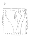
- Initial test results are shown in Fig. 4 for a valve having a single annular slit. The valve was spring actuated; that is, the two valve members were pressed toward each other by a spring. Liquid was supplied to the valve by a constant flow pump and flow through the valve was controlled by bypassing some liquid.
- the space between the valve members, and thus the pressure was controlled.
- the average diameter of the globules in the emulsion product were then plotted against flow rate. From the flow rate, fluid pressures and valve geometry the gap could then be calculated. The calculated gap is shown for the valve operating at 1500 psi (10.35 MPa) inlet pressure.
- Fig. 4 shows that the degree of homogenization increases, or the globule size decreases, as the gap of a knife edge valve decreases. A strong contrast can be seen in the decrease in homogenization with a conventional flat valve as the gap height h is decreased.
- the emulsion used in the test was filled milk of 3.5% corn oil, 8% non-fat milk solids and 88.5% water. The average emulsion droplet diameter was determined using a recognized spectroturbidimetric technique.
- Fig. 5 the average globule diameter is plotted against pressure for three linear slit valves (Fig. 11) similar to those described in U.S. Patent 4,081,863 to Rees.
- the slit cross sectional areas of the three valves were equal: one valve has a gap of .018 inch (0.457mm) and a length of .75 inches (19.05mm); a second valve had a gap of .006 inch (0.1524mm) and a length of 2.25 inches (57.15mm); and a third valve had a gap of .003 inch (0.076mm) and a length of 4.50 inches (114.3mm). It can be seen from the data in Fig.
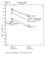
- Fig. 6 indicates the improved homogenizing efficiency which may be achieved at a given flow rate by reducing the gap of a knife edge annular slit valve.
- additional valve members were stacked to provide from two to ten parallel annular slits. The specific number of valve slits provided in each assembly for which the data was plotted is shown adjacent each data point.
- Fig. 6 shows that for a given homogenizing pressure and a given flow rate, the homogenizing efficiency can be increased by reducing the gap and increasing the total slit length of the valve assembly.
- Fig. 6 also indicates that the high homogenizing efficiency attained at 480 gallons per hour (1819 1/h) with a single annular knife edge valve (Fig. 4) can be obtained for about three times that flow rate using a multislit valve.
- the gap is widened to about .003 inch (0.076mm) the results obtained are comparable to those obtained with a single slit knife edge valve of wider gap.
- the total slit length is controlled by the number of valve rings, it is varied by discrete amounts.
- the 1500 gallons per hour (5685 1/h) is only a nominal flow rate, and the actual flow through the assembly varies from 1250 gallons per hour (4738 1/h) to 1670 gallons per hour (6329 1/h).
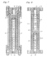
- FIG. 7 A valve assembly suitable for high flow rate homogenizing systems and used to obtain the data of Fig. 6 is shown in Fig. 7.
- This valve assembly includes 14 valve members 70 stacked in the same manner that valve members 32 and 34 are stacked in the embodiment of Fig. 1.
- a valve retainer 72 is provided as before.
- the valve members 70 and retainer 72 are surrounded by a cylindrical outer casing 73 to which end plates 74 and 76 are bolted.
- a central bore 78 is defined by the many valve members.
- the bore 78 is in fluid communication with an inlet/ outlet port 80.
- An outer chamber 82 defined by the many peripheral ports in the valve members is in fluid communication with an inlet/outlet port 84.
- Fig. 8 indicates the manner in which the valve assembly of Fig. 7 can be customized to provide for reduced flow rates at a given homogenizing pressure or to allow for the use of higher homogenizing pressures without increasing the flow rate.
- the retainer 72 and a number of the valves members 70 are rearranged such that the retainer 72 provides a bypass around the valve members above it.
- the manifold 86 in the retainer 72 equalizes the fluid pressure between the central bore 88 of the upper valve members and the peripheral ports 90 of those valve members.
- the pressure differential is maintained, however, between the central bore 92 of the lower valve members and the peripheral ports 94.
- the total cross sectional area of the homogenizing valve slits is reduced.
- the homogenizing pressure of the emulsion is held at the same pressure as with a full stack of valve members, the flow rate is reduced. Similarly, the flow rate can be held to the same level as with the arrangement of Fig. 7 if the homogenizing pressure is increased accordingly.
- This embodiment illustrates an important feature of the present invention.
- the flow rate for a valve having a given circumference was determined by the pressure and the gap between the valve seat and the plate.
- gap is held to a critical optimum for all flow rates of the assembly.
- Flow rate is determined solely by the pressure and the total cross sectional area of the valve slits rather than by the valve gap.
- the graph of Fig. 9 shows the results of a test of the homogenizing valve of Figs. 7 and 8. A single run of a conventional valve is also shown for comparison. In both cases the homogizer pumped at a rate of 23 gpm (87.17 1/min) but some of the flow was bypassed when the knife edge valve was tested. It can be seen that the same degree of homogenization can be obtained at a much lower pressure using the valve of this invention.
- the power requirement for homogenizing a unit of emulsion is proportional to the product of flow rate and homogenizing pressure.
- the power ratio of the novel and convention valves at an average homogized diameter of .8 micrometer (Am) is:
- FIG. 10 A modification of the stacked ring valve is shown in Fig. 10.
- this embodiment includes a plurality of valve members 150 stacked within a cylindrical casing 152.
- the valve seats 154 are machined so that each is slightly higher than the outer rim 156 of each valve member. This provides the optimum valve gap without the use of shims.
- Fig. 10 also includes a hydraulic valve actuator (HVA) 158 which allows for widening of the valve slits to purge any sediments which may have collected in the slits.
- HVAC hydraulic valve actuator
- high pressure hydraulic fluid presses downwardly against a piston 168 to force a piston rod 166 against a pressure distributing plate 164.
- the plate 164 is thereby forced downwardly against the stack of rings to compress wave springs 162 positioned between the valve members. With the valve members thus pressed closely against each other the optimum spacing is provided between the valve seats and the opposing valve surfaces. If, on the otherhand, the pressure in chamber 160 is reduced, the springs 162 are able to spread the valve members apart to increase the valve gaps.
- the HVA 158 is positioned above the stack of valve members 150, and both the inlet and outlet ports are provided at the lower end of the assembly.
- High pressure fluid is directed to the center chamber within the stack of valve members by an inlet port 170.
- the fluid is then expressed radially out through the valve slits into the peripheral low pressure chamber provided by the valve members.
- the low pressure homogenized fluid is then directed downward to an annulus 172 and outward through the outlet port 174.
- valve actuator such as shown in Fig. 10
- the upward force against the valve actuator is equal to the wave ' spring force plus the product of the fluid pressure within the central high pressure chamber and the projected area of the retainer 169 and top valve ring 171 exposed to that high pressure.
- the downward compressive force against the stack of valve members is equal to the product of the hydraulic pressure in chamber 160 and the top surface area of piston 168. If only a few large diameter valve members were utilized, a large diameter HVA would be required to overcome the upward force at a reasonable hydraulic pressure. However, by stacking a large number of valve members to obtain the desired flow rate, the diameter of retainer 169 and thus the size of the HVA can be minimized.
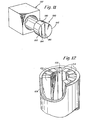
- a slit valve such as taught in U.S. Patent 4,081,863 but modified in accordance with this invention is shown in Fig. 11.
- high pressure fluid is directed through a slit assembly 180 positioned within a fluid conduit 182.
- Two linear valve slits 184 and 186 are formed between segments 188, 190 and 192 of the valve assembly 180.
- these slits are formed with a knife edge configuration and the gap of each slit is less than .003 inches (0.076mm).
- a central passage 102 and peripheral passages 104 in a valve assembly are formed by a number of axially extending bars 106 spaced around the inner surface of a cylindrical casing 108. A slight space is provided between the adjacent edges of the bars to provide the valve slits.
- the gap of each of those valve slits is less than about .003 inches (0.076mm) and is preferably .001 inches (0.025mm).
- a plate 110 extends between two discs 112 and 114 positioned within a cylindrical casing 116.
- a high pressure chamber is in fluid communication with an emulsion supply through port 118 in the disc 112.
- a low pressure chamber on the opposite side of the plate is in fluid communication with an outlet port 120 in the disc 114.
- a slit 122 is formed in the plate 110 and that slit has a gap of less than about .003 inches (0.076mm).
- a stack of frustroconical washers 124 is held in compression between an end plate 126 and a retainer 128 by a compression spring 130.
- the space 132 within the several washers forms the high pressure chamber, and a low pressure chamber 134 surrounds the washers.
- the washers are sufficiently resilient that under high pressure they spread slightly to provide the necessary gaps along the interfacing edges 136.
- the gap can be decreased by increasing the compression force and can be increased by decreasing that force.
- the flow rate for a given homogenizing pressure can be determined by the number of washers provided.
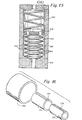
- a final embodiment of the invention is shown in Figs. 16 and 17.
- This valve assembly comprises a central sleeve 136 having a wide longitudinal slit 138 therein.
- This sleeve is positioned in a larger sleeve 140'which also has a wide slit 142. Both sleeves are positioned within an outer casing 144.
Landscapes
- Chemical & Material Sciences (AREA)
- Dispersion Chemistry (AREA)
- Chemical Kinetics & Catalysis (AREA)
- Life Sciences & Earth Sciences (AREA)
- Animal Husbandry (AREA)
- Environmental Sciences (AREA)
- Other Liquid Machine Or Engine Such As Wave Power Use (AREA)
- Pipe Accessories (AREA)
- Lift Valve (AREA)
- Beverage Vending Machines With Cups, And Gas Or Electricity Vending Machines (AREA)
- Bidet-Like Cleaning Device And Other Flush Toilet Accessories (AREA)
- Special Spraying Apparatus (AREA)
- Agricultural Chemicals And Associated Chemicals (AREA)
- Bakery Products And Manufacturing Methods Therefor (AREA)
- Non-Alcoholic Beverages (AREA)
Priority Applications (1)
| Application Number | Priority Date | Filing Date | Title |
|---|---|---|---|
| AT80301474T ATE10441T1 (de) | 1980-01-29 | 1980-05-06 | Vorrichtung und verfahren zum homogenisieren von fluida. |
Applications Claiming Priority (2)
| Application Number | Priority Date | Filing Date | Title |
|---|---|---|---|
| US06/116,601 US4352573A (en) | 1980-01-29 | 1980-01-29 | Homogenizing method |
| US116601 | 2002-04-04 |
Publications (4)
| Publication Number | Publication Date |
|---|---|
| EP0034675A2 true EP0034675A2 (de) | 1981-09-02 |
| EP0034675A3 EP0034675A3 (en) | 1981-09-23 |
| EP0034675B1 EP0034675B1 (de) | 1984-11-28 |
| EP0034675B2 EP0034675B2 (de) | 1988-08-24 |
Family
ID=22368163
Family Applications (1)
| Application Number | Title | Priority Date | Filing Date |
|---|---|---|---|
| EP80301474A Expired EP0034675B2 (de) | 1980-01-29 | 1980-05-06 | Vorrichtung zum Homogenisieren von Fluida |
Country Status (6)
| Country | Link |
|---|---|
| US (1) | US4352573A (de) |
| EP (1) | EP0034675B2 (de) |
| JP (1) | JPS57117327A (de) |
| AT (1) | ATE10441T1 (de) |
| DE (1) | DE3069692D1 (de) |
| DK (1) | DK159528C (de) |
Cited By (8)
| Publication number | Priority date | Publication date | Assignee | Title |
|---|---|---|---|---|
| EP0852906A1 (de) | 1997-01-13 | 1998-07-15 | Bayer Ag | Verfahren und Vorrichtung zum Homogenisieren von Milch |
| WO1999044413A1 (en) * | 1998-03-02 | 1999-09-10 | Foss Electric A/S | Method and apparatus for homogenizing a fluid |
| CN1120744C (zh) * | 1997-03-13 | 2003-09-10 | Apv均化器集团 | 均化阀门 |
| WO2009096825A1 (en) | 2008-01-29 | 2009-08-06 | Tetra Laval Holdings & Finance S.A. | A homogenizer valve |
| WO2012084986A1 (en) | 2010-12-22 | 2012-06-28 | Tetra Laval Holdings & Finance S.A. | Homogenizing valve |
| WO2017064496A1 (en) * | 2015-10-13 | 2017-04-20 | Thomas Swan & Co.Ltd | Apparatus and method for bulk production of atomically thin 2-dimensional materials including graphene |
| DE102021004243A1 (de) | 2021-08-20 | 2023-02-23 | Gea Mechanical Equipment Italia S.P.A. | Ventil |
| IT202300000933A1 (it) | 2023-01-23 | 2024-07-23 | Gea Mech Equipment Italia S P A | Valvola multi-gap e apparato omogeneizzante comprendente detta valvola multi-gap |
Families Citing this family (28)
| Publication number | Priority date | Publication date | Assignee | Title |
|---|---|---|---|---|
| US4534388A (en) * | 1983-06-07 | 1985-08-13 | Pall Corporation | Dispersion system and method |
| JPS6128429A (ja) * | 1983-10-21 | 1986-02-08 | Kazuo Ogata | 均質機の分割式均質装置 |
| JPS60108339U (ja) * | 1983-12-27 | 1985-07-23 | 株式会社 村田製作所 | 多段均質機 |
| US4585357A (en) * | 1984-10-18 | 1986-04-29 | Kazuo Ogata | Homogenizer |
| DE3611909C3 (de) * | 1986-04-09 | 2000-03-16 | Ruhrgas Ag | Vorrichtung zur Steuerung der Menge und/oder des Mischungsverhältnisses eines Brenngas-Luft-Gemisches |
| US4946702A (en) * | 1988-03-31 | 1990-08-07 | The Procter & Gamble Company | Low viscosity orange juice concentrates useful for high Brix products having lower pseudoplasticity and greater dispersibility |
| SE468341C (sv) * | 1991-03-20 | 1997-08-04 | Kvaerner Pulping Tech | Apparat för blandning av en suspension av ett cellulosahaltigt fibermaterial och ett fluidum |
| NO174015C (no) * | 1991-10-24 | 1994-03-02 | Bjoern Dybdahl | Anordning til aa kunne bringe et blandelegeme inn i og ut fra en roerledning |
| US5232726A (en) * | 1992-10-08 | 1993-08-03 | The Coca-Cola Company | Ultra-high pressure homogenization of unpasteurized juice |
| US5460449A (en) * | 1994-01-27 | 1995-10-24 | Kent; J. Howard | In-line mixer for dispersions |
| JP2975943B2 (ja) * | 1996-02-20 | 1999-11-10 | 農林水産省食品総合研究所長 | エマルションの製造方法及びエマルションの製造装置 |
| FR2748954B1 (fr) * | 1996-05-21 | 1998-07-24 | Pavese Guy | Module homogeneisateur-emulsionneur ultra colloidal a haut rendement pour fluides reputes non miscibles et procede associe |
| DE19626246A1 (de) * | 1996-06-29 | 1998-01-08 | Buehler Ag | Spaltmühle |
| US5976232A (en) * | 1998-04-30 | 1999-11-02 | Hewlett-Packard Company | Homogenization process for ink-jet inks containing fine dispersions of pigments |
| US6305836B1 (en) | 1999-07-09 | 2001-10-23 | Apv North America, Inc. | Force absorbing homogenization valve |
| US6238080B1 (en) | 1999-07-09 | 2001-05-29 | Apv North America, Inc. | Homogenization valve with outside high pressure volume |
| US6244739B1 (en) | 1999-07-09 | 2001-06-12 | Apv North America, Inc. | Valve members for a homogenization valve |
| JP2001065780A (ja) * | 1999-09-01 | 2001-03-16 | Gijutsu Kaihatsu Sogo Kenkyusho:Kk | 脈動減衰装置 |
| DE60030290T2 (de) | 2000-10-05 | 2007-08-23 | Bertoli S.R.L., Vicofertile | Homogenisierungsventil |
| US6502979B1 (en) * | 2000-11-20 | 2003-01-07 | Five Star Technologies, Inc. | Device and method for creating hydrodynamic cavitation in fluids |
| ATE398485T1 (de) * | 2002-01-09 | 2008-07-15 | Beryu Co Ltd | Emulgier-/dispergiersystem |
| US20040215697A1 (en) * | 2003-04-11 | 2004-10-28 | Vasileios Vergopoulos | Systems and methods for managing unit operating data |
| US9010995B2 (en) * | 2012-03-16 | 2015-04-21 | Slack Chemical Co, Inc. | Mixing apparatus and method |
| US9399201B1 (en) | 2012-09-28 | 2016-07-26 | Fristam Pumps, USA | Homogenizer for reducing the size of particles in fluids |
| ITPR20130081A1 (it) * | 2013-10-21 | 2015-04-22 | Gea mechanical equipment italia spa | Valvola omogeneizzante, in particolare per applicazione a fluidi fibrosi |
| CA2972790A1 (en) | 2016-07-11 | 2018-01-11 | Exceldor Foods Ltd. | Oil-in-water emulsions for meat and poultry products and methods of producing same |
| DE102023002857B4 (de) | 2023-07-14 | 2026-05-07 | Hst Maschinenbau Gmbh | Homogenisierventil |
| DE102024001822A1 (de) | 2024-06-06 | 2025-12-11 | Gea Mechanical Equipment Italia S.P.A. | Homogenisierventil |
Family Cites Families (24)
| Publication number | Priority date | Publication date | Assignee | Title |
|---|---|---|---|---|
| US1533843A (en) * | 1925-04-14 | of london | ||
| DE182557C (de) * | ||||
| US366169A (en) * | 1887-07-05 | John w | ||
| US973328A (en) * | 1910-04-02 | 1910-10-18 | Joseph Willmann | Emulsifier. |
| US996704A (en) * | 1910-09-19 | 1911-07-04 | Frank P Cribbins | Machine for homogenizing milk. |
| US1070226A (en) * | 1911-10-23 | 1913-08-12 | Dairy Machinery And Construction Company Inc | Homogenizer. |
| US1070218A (en) * | 1912-06-21 | 1913-08-12 | Joseph Willmann | Homogenizer. |
| US1112594A (en) * | 1912-08-28 | 1914-10-06 | Henry N Brawner Jr | Method or process of homogenizing cream. |
| US1436947A (en) * | 1922-10-26 | 1922-11-28 | E F Comezys | Process for preserving lacteal fluids |
| GB487584A (en) * | 1936-12-19 | 1938-06-22 | Hendrik Van Bilderbeek Jr | Improvements in or relating to apparatus for preparing and drawing off whipped creamor similar products |
| US2882025A (en) * | 1955-06-16 | 1959-04-14 | Carnation Co | Homogenizing valve |
| DE1880739U (de) * | 1958-11-14 | 1963-10-17 | Oliwska Fabryka Masz I Urzadze | Vorrichtung zum homogenisieren von fettkuegelchen enthaltenden fluessigkeiten. |
| NL124907C (de) * | 1960-10-13 | |||
| US3179385A (en) * | 1961-11-17 | 1965-04-20 | Manton Gaulin Mfg Company Inc | Method and apparatus for processing fluids |
| US3526391A (en) * | 1967-01-03 | 1970-09-01 | Wyandotte Chemicals Corp | Homogenizer |
| JPS5211221B1 (de) * | 1969-03-17 | 1977-03-29 | ||
| FR2039562A5 (de) * | 1969-04-09 | 1971-01-15 | Elf Distribution | |
| US3732851A (en) * | 1971-05-26 | 1973-05-15 | R Self | Method of and device for conditioning steam |
| IT1022977B (it) * | 1974-10-17 | 1978-04-20 | Figli Spa | Procedimento e apparecchiatura per la omogeneizzazione di liquidi |
| US4081863A (en) * | 1975-07-23 | 1978-03-28 | Gaulin Corporation | Method and valve apparatus for homogenizing fluid emulsions and dispersions and controlling homogenizing efficiency and uniformity of processed particles |
| US4160002A (en) * | 1976-06-09 | 1979-07-03 | Janovtchik Viacheslav J | Steam injectors |
| DE2729855C2 (de) * | 1977-07-01 | 1985-08-01 | Marugg, Max Hermann, Zizers | Homogenisiervorrichtung zum Homogenisieren einer flüssigen oder breiigen Substanz |
| US4205696A (en) * | 1978-09-18 | 1980-06-03 | Innerspace Corporation | Fluid control valve |
| JPS5584528A (en) * | 1978-12-21 | 1980-06-25 | Showa Yuka Kk | Mixer |
-
1980
- 1980-01-29 US US06/116,601 patent/US4352573A/en not_active Expired - Lifetime
- 1980-05-05 DK DK195580A patent/DK159528C/da not_active IP Right Cessation
- 1980-05-06 AT AT80301474T patent/ATE10441T1/de not_active IP Right Cessation
- 1980-05-06 EP EP80301474A patent/EP0034675B2/de not_active Expired
- 1980-05-06 DE DE8080301474T patent/DE3069692D1/de not_active Expired
-
1981
- 1981-01-29 JP JP56012180A patent/JPS57117327A/ja active Granted
Cited By (19)
| Publication number | Priority date | Publication date | Assignee | Title |
|---|---|---|---|---|
| EP0852906A1 (de) | 1997-01-13 | 1998-07-15 | Bayer Ag | Verfahren und Vorrichtung zum Homogenisieren von Milch |
| US6085644A (en) * | 1997-01-13 | 2000-07-11 | Bayer Aktiengesellschaft | Process and device for homogenizing milk |
| AU726373B2 (en) * | 1997-01-13 | 2000-11-02 | Symrise Gmbh & Co. Kg | Process and device for homogenizing milk |
| CN1120744C (zh) * | 1997-03-13 | 2003-09-10 | Apv均化器集团 | 均化阀门 |
| WO1999044413A1 (en) * | 1998-03-02 | 1999-09-10 | Foss Electric A/S | Method and apparatus for homogenizing a fluid |
| WO2009096825A1 (en) | 2008-01-29 | 2009-08-06 | Tetra Laval Holdings & Finance S.A. | A homogenizer valve |
| US8944673B2 (en) | 2008-01-29 | 2015-02-03 | Tetra Laval Holdings & Finance S.A. | Homogenizer valve |
| WO2012084986A1 (en) | 2010-12-22 | 2012-06-28 | Tetra Laval Holdings & Finance S.A. | Homogenizing valve |
| WO2017064496A1 (en) * | 2015-10-13 | 2017-04-20 | Thomas Swan & Co.Ltd | Apparatus and method for bulk production of atomically thin 2-dimensional materials including graphene |
| CN108137328A (zh) * | 2015-10-13 | 2018-06-08 | 托马仕有限责任公司 | 批量生产包括石墨烯的原子级薄二维材料的设备和方法 |
| GB2543486B (en) * | 2015-10-13 | 2018-07-18 | Swan Thomas & Co Ltd | Apparatus and method of using the apparatus for bulk production of atomically thin 2-dimensional materials including graphene |
| ES2681960R1 (es) * | 2015-10-13 | 2018-10-09 | Thomas Swan & Co.Ltd | Aparato y procedimiento para la producción a granel de materiales de dos dimensiones atómicamente delgados incluyendo grafeno |
| US10822238B2 (en) | 2015-10-13 | 2020-11-03 | Thomas Swan & Co. Ltd. | Apparatus and method for bulk production of atomically thin 2- dimensional materials including graphene |
| DE102021004243A1 (de) | 2021-08-20 | 2023-02-23 | Gea Mechanical Equipment Italia S.P.A. | Ventil |
| WO2023021349A1 (en) | 2021-08-20 | 2023-02-23 | Gea Mechanical Equipment Italia S.P.A. | Valve |
| DE102021004243B4 (de) | 2021-08-20 | 2023-11-30 | Gea Mechanical Equipment Italia S.P.A. | Ventil und Verwendung eines Ventils |
| US12253183B2 (en) | 2021-08-20 | 2025-03-18 | Gea Mechanical Equipment Italia S.P.A. | Valve |
| IT202300000933A1 (it) | 2023-01-23 | 2024-07-23 | Gea Mech Equipment Italia S P A | Valvola multi-gap e apparato omogeneizzante comprendente detta valvola multi-gap |
| WO2024157058A1 (en) | 2023-01-23 | 2024-08-02 | Gea Mechanical Equipment Italia S.P.A. | Multi-gap valve and homogenizing apparatus comprising said multi-gap valve |
Also Published As
| Publication number | Publication date |
|---|---|
| JPS6110170B2 (de) | 1986-03-28 |
| DK159528C (da) | 1991-04-02 |
| DK159528B (da) | 1990-10-29 |
| EP0034675A3 (en) | 1981-09-23 |
| EP0034675B2 (de) | 1988-08-24 |
| ATE10441T1 (de) | 1984-12-15 |
| US4352573A (en) | 1982-10-05 |
| DK195580A (da) | 1981-07-30 |
| EP0034675B1 (de) | 1984-11-28 |
| DE3069692D1 (en) | 1985-01-10 |
| JPS57117327A (en) | 1982-07-21 |
Similar Documents
| Publication | Publication Date | Title |
|---|---|---|
| US4352573A (en) | Homogenizing method | |
| US5899564A (en) | Homogenization valve | |
| US4383769A (en) | Homogenizing apparatus and method | |
| RU2201795C2 (ru) | Клапан гомогенизатора | |
| DE10351962B4 (de) | Homogenisierapparat | |
| US6764213B2 (en) | Forming emulsions | |
| EP3710146B1 (de) | Querstromanordnung und verfahren für durch membranemulgierung kontrollierte tröpfchenerzeugung | |
| EP1121192B1 (de) | Verfahren zur homogenisierung | |
| DE3728946C2 (de) | ||
| US20150173322A1 (en) | Homogenizer valve | |
| US6244739B1 (en) | Valve members for a homogenization valve | |
| DE69224593T2 (de) | Konstant-Durchfluss-Regelventil mit Schnellstart bei niederem Eingangsdruck | |
| EP1196235B1 (de) | Homogenisierungsventil | |
| WO1999011943A1 (de) | Regler zur regelung des fluidstromes einer hydrostatik- oder aerostatikvorrichtung | |
| US6305836B1 (en) | Force absorbing homogenization valve | |
| EP0724477A1 (de) | Homogenisierungsköpfe | |
| EP0840190A2 (de) | Druckregler für den Medienstrom eines Hydrostatik-oder Aerostatik-Lagers | |
| US5498075A (en) | Premix homogenizing system | |
| JPH1142430A (ja) | 微粒化装置 | |
| KR20240047944A (ko) | 크로스-플로우 멤브레인 에멀젼화 어셈블리용 인서트 | |
| RU2021848C1 (ru) | Гомогенизирующий клапан для получения высокодисперсных эмульсий | |
| JPH0227879Y2 (de) | ||
| JPH1142432A (ja) | 微粒化方法および装置 |
Legal Events
| Date | Code | Title | Description |
|---|---|---|---|
| PUAI | Public reference made under article 153(3) epc to a published international application that has entered the european phase |
Free format text: ORIGINAL CODE: 0009012 |
|
| PUAL | Search report despatched |
Free format text: ORIGINAL CODE: 0009013 |
|
| AK | Designated contracting states |
Designated state(s): AT BE CH DE FR GB IT LI LU NL SE |
|
| AK | Designated contracting states |
Designated state(s): AT BE CH DE FR GB IT LI LU NL SE |
|
| 17P | Request for examination filed |
Effective date: 19820312 |
|
| ITF | It: translation for a ep patent filed | ||
| GRAA | (expected) grant |
Free format text: ORIGINAL CODE: 0009210 |
|
| AK | Designated contracting states |
Designated state(s): AT BE CH DE FR GB IT LI LU NL SE |
|
| REF | Corresponds to: |
Ref document number: 10441 Country of ref document: AT Date of ref document: 19841215 Kind code of ref document: T |
|
| REF | Corresponds to: |
Ref document number: 3069692 Country of ref document: DE Date of ref document: 19850110 |
|
| ET | Fr: translation filed | ||
| PG25 | Lapsed in a contracting state [announced via postgrant information from national office to epo] |
Ref country code: LU Free format text: LAPSE BECAUSE OF NON-PAYMENT OF DUE FEES Effective date: 19850531 |
|
| PLBI | Opposition filed |
Free format text: ORIGINAL CODE: 0009260 |
|
| 26 | Opposition filed |
Opponent name: BRAN & LUEBBE GMBH Effective date: 19850824 |
|
| NLR1 | Nl: opposition has been filed with the epo |
Opponent name: BRAN & LUEBBE GMBH |
|
| PGFP | Annual fee paid to national office [announced via postgrant information from national office to epo] |
Ref country code: AT Payment date: 19860522 Year of fee payment: 7 |
|
| PUAH | Patent maintained in amended form |
Free format text: ORIGINAL CODE: 0009272 |
|
| STAA | Information on the status of an ep patent application or granted ep patent |
Free format text: STATUS: PATENT MAINTAINED AS AMENDED |
|
| 27A | Patent maintained in amended form |
Effective date: 19880824 |
|
| AK | Designated contracting states |
Kind code of ref document: B2 Designated state(s): AT BE CH DE FR GB IT LI LU NL SE |
|
| ITF | It: translation for a ep patent filed | ||
| NLR2 | Nl: decision of opposition | ||
| NLR3 | Nl: receipt of modified translations in the netherlands language after an opposition procedure | ||
| ET3 | Fr: translation filed ** decision concerning opposition | ||
| PG25 | Lapsed in a contracting state [announced via postgrant information from national office to epo] |
Ref country code: AT Effective date: 19890506 |
|
| PG25 | Lapsed in a contracting state [announced via postgrant information from national office to epo] |
Ref country code: LI Effective date: 19890531 Ref country code: CH Effective date: 19890531 |
|
| REG | Reference to a national code |
Ref country code: CH Ref legal event code: PL |
|
| PGFP | Annual fee paid to national office [announced via postgrant information from national office to epo] |
Ref country code: BE Payment date: 19910715 Year of fee payment: 12 |
|
| PG25 | Lapsed in a contracting state [announced via postgrant information from national office to epo] |
Ref country code: BE Effective date: 19920531 |
|
| PGFP | Annual fee paid to national office [announced via postgrant information from national office to epo] |
Ref country code: NL Payment date: 19920531 Year of fee payment: 13 |
|
| BERE | Be: lapsed |
Owner name: GAULIN CORP. Effective date: 19920531 |
|
| PGFP | Annual fee paid to national office [announced via postgrant information from national office to epo] |
Ref country code: FR Payment date: 19930330 Year of fee payment: 14 |
|
| ITTA | It: last paid annual fee | ||
| PG25 | Lapsed in a contracting state [announced via postgrant information from national office to epo] |
Ref country code: NL Effective date: 19931201 |
|
| NLV4 | Nl: lapsed or anulled due to non-payment of the annual fee | ||
| EAL | Se: european patent in force in sweden |
Ref document number: 80301474.5 |
|
| PG25 | Lapsed in a contracting state [announced via postgrant information from national office to epo] |
Ref country code: FR Effective date: 19950131 |
|
| REG | Reference to a national code |
Ref country code: FR Ref legal event code: ST |
|
| PGFP | Annual fee paid to national office [announced via postgrant information from national office to epo] |
Ref country code: SE Payment date: 19990414 Year of fee payment: 20 |
|
| PGFP | Annual fee paid to national office [announced via postgrant information from national office to epo] |
Ref country code: GB Payment date: 19990430 Year of fee payment: 20 |
|
| PGFP | Annual fee paid to national office [announced via postgrant information from national office to epo] |
Ref country code: DE Payment date: 19990624 Year of fee payment: 20 |
|
| PG25 | Lapsed in a contracting state [announced via postgrant information from national office to epo] |
Ref country code: GB Free format text: LAPSE BECAUSE OF EXPIRATION OF PROTECTION Effective date: 20000505 |
|
| PG25 | Lapsed in a contracting state [announced via postgrant information from national office to epo] |
Ref country code: SE Free format text: THE PATENT HAS BEEN ANNULLED BY A DECISION OF A NATIONAL AUTHORITY Effective date: 20000530 |
|
| REG | Reference to a national code |
Ref country code: GB Ref legal event code: PE20 Effective date: 20000505 |
|
| EUG | Se: european patent has lapsed |
Ref document number: 80301474.5 |