EP0034679B1 - Gehäuse für ein Befestigungselemententreibwerkzeug - Google Patents
Gehäuse für ein Befestigungselemententreibwerkzeug Download PDFInfo
- Publication number
- EP0034679B1 EP0034679B1 EP80303941A EP80303941A EP0034679B1 EP 0034679 B1 EP0034679 B1 EP 0034679B1 EP 80303941 A EP80303941 A EP 80303941A EP 80303941 A EP80303941 A EP 80303941A EP 0034679 B1 EP0034679 B1 EP 0034679B1
- Authority
- EP
- European Patent Office
- Prior art keywords
- assembly
- barrel
- fastener
- pad
- jaw
- Prior art date
- Legal status (The legal status is an assumption and is not a legal conclusion. Google has not performed a legal analysis and makes no representation as to the accuracy of the status listed.)
- Expired
Links
- 238000009434 installation Methods 0.000 description 12
- 238000009413 insulation Methods 0.000 description 8
- 239000002184 metal Substances 0.000 description 4
- 230000000712 assembly Effects 0.000 description 3
- 238000000429 assembly Methods 0.000 description 3
- 238000013459 approach Methods 0.000 description 1
- 230000005484 gravity Effects 0.000 description 1
- 230000000284 resting effect Effects 0.000 description 1
- 239000007787 solid Substances 0.000 description 1
Images
Classifications
-
- B—PERFORMING OPERATIONS; TRANSPORTING
- B25—HAND TOOLS; PORTABLE POWER-DRIVEN TOOLS; MANIPULATORS
- B25B—TOOLS OR BENCH DEVICES NOT OTHERWISE PROVIDED FOR, FOR FASTENING, CONNECTING, DISENGAGING OR HOLDING
- B25B23/00—Details of, or accessories for, spanners, wrenches, screwdrivers
- B25B23/02—Arrangements for handling screws or nuts
- B25B23/04—Arrangements for handling screws or nuts for feeding screws or nuts
-
- E—FIXED CONSTRUCTIONS
- E04—BUILDING
- E04D—ROOF COVERINGS; SKY-LIGHTS; GUTTERS; ROOF-WORKING TOOLS
- E04D15/00—Apparatus or tools for roof working
- E04D15/04—Apparatus or tools for roof working for roof coverings comprising slabs, sheets or flexible material
- E04D2015/042—Fixing to the roof supporting structure
- E04D2015/047—Fixing to the roof supporting structure by screwing
Definitions
- This invention relates to a barrel assembly, suitable for connecting to a fastener driving tool having a tool body and a driver, said barrel assembly being adapted for attachment at one end to the tool body, and including an annular wall, a bore, and an elongated slot which increases in depth from a starting point on the outer surface of the annular wall and terminates in a through opening in registry with the bore.
- fastener driving tools have been developed for driving fasteners into workpieces.
- the intended application of the driving tools often involves problems which require unique solutions.
- One such application requiring a special driving tool is the installation of insulation on a metal roof deck.
- the insulation is normally held to the roof deck by means of enlarged washer-like plates through which extends an elongated threaded fastener or nail type fastener.
- the insulation may be six inches (15.24 cms) thick or more and, therefore, the fastener, which often approaches seven or eight inches (17.78 or 20.32 cms), must be held in proper alignment so that it properly penetrates the insulation and the metal roof deck.
- a number of fastener entrant means have been proposed heretofore.
- United States Patent Specification No. 3,973,605 there is disclosed a breach-type barrel assembly which opens in the manner of a shotgun to receive a hand fed fastener.
- United States Patent Specification No. 4,081,254 there is disclosed a barrel assembly in which a strip which carries fasteners passes through a slot in a wall of the barrel assembly to sequentially place the fasteners within the barrel bore.
- Other patent specifications have heretofore proposed entrant means in barrel assemblies wherein the fastener is hand fed through appropriate slots in the barrel wall into the barrel bore. Exemplary of these patent specifications are United States Patent Specifications Nos. 2,845,968, 2,484,655, Netherlands Patent Specification No.
- the latter Specification discloses a screw-runner comprising a central channel into which screws may be fed via a sliding channel.
- the sliding channel is inclined to the axis of the central channel, increases in depth as it penetrates a wall of the central channel, and terminates in a through opening in registry with the central channel, but is not well suited for handling long fasteners.
- a number of patent specifications disclose power operated screwdrivers which include automatic means for feeding fasteners. Exemplary of these patent specifications are United States Patent Specifications Nos. 3,907,014, 3,524,484, 2,922,447 and 2,327,074. Several of the above-mentioned patent specifications also teach various jaw assemblies for holding the fastener in alignment at the time of installation. Other patent specifications which teach means for holding the fastener within the barrel at the time of installation include United States Patent Specifications Nos. 3,056,441, 1,889,330 and 3,266,537.
- a commonly used tool for installing insulation on roof deck includes a tube feed.
- the incidence of bowed fasteners increases with fastener length and this in turn causes jamming within the tube feed.
- the barrel must be extremely long to accommodate a fastener fed at an angle to the barrel. Because of the required length of the barrel assemblies, the overall weight is increased. In addition, the tool becomes cumbersome, and wear problems and alignment problems increase.
- a barrel assembly of the type described above characterised in that the slot increases in width from the starting point and that the through opening is enlarged to accommodate a fastener head.
- the barrel assembly of the present invention is thus particularly applicable to the handling of long fasteners in which alignment of the fastener and wear and tear on the equipment have heretofore been a problem.
- the barrel assembly is adapted for use with an installation tool primarily intended for the installation of long fasteners through insulation and into a roof deck.
- the barrel assembly comprises a retractable barrel which cooperates with an inner sleeve and which includes a clear through notch in registry with the elongated slot to receive the fastener in the barrel bore.
- a jaw assembly may be included in a workpiece pad connected at the end of the barrel. Spring loaded jaws may slidably engage a wear plate which receives a major portion of the thrust of the installation tool during use.
- a footpad or other holding means may be provided to assist in holding the installation tool firmly against the workpiece.
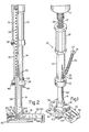
- a barrel assembly is adapted for attachment to the tool body of a standard driving tool 11 of the type used to drive fasteners 24 into a workpiece (not shown), Figure 1.
- the barrel assembly 10 includes an outer sleeve 12 adapted for connection to the driving tool 11, Figures 1 and 2.
- a retractable inner sleeve 14 is attached to and is retractable into the outer sleeve 12.
- a retractable barrel 16 is retractably connected to the inner sleeve 14, and a workpiece or jaw assembly pad 18 having a footpad 52 extending outward therefrom is connected at the distal end of the barrel 16.
- the jaw assembly pad 18 is adapted to receive and guide a fastener 24 out of the barrel assembly 10 while engaging the workpiece.
- the retractable barrel 16 and retractable inner sleeve 14 are biased towards an extended position by means of a coil spring 26 which engages the driving tool 11 at one end and the barrel 16 at the other end.
- the axial extent of the inner sleeve 14 in the barrel 16 in an extended position is controlled by an adjusting pin 48 extending upwards through a flange 32 of the inner sleeve 14.
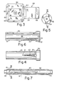
- the inner sleeve 14 has an annular wall and contains a central bore 36 extending the length thereof, Figure 6.
- the slot 20 which forms the entrant means for the fastener 24, increases in depth within the wall of the inner sleeve 14 along its length from the starting point 21 to its terminal end where it terminates in an enlarged clear through opening 22 which communicates with the central bore 36 and which accommodates a head 25 of the fastener 24.
- the slot 20 likewise increases in width from its starting point 21 to the clear through opening 22.
- a blind groove 34 extends from the clear through opening 22 longitudinally through the interior of the end flange 32, although a clear through groove could also be employed.
- the driver 15 is positioned at the tool body end of the clear through opening 22 in said extended position of the inner sleeve 14 and barrel 16 so that the barrel assembly can receive the fasteners 24.
- the barrel 16 has a central bore 42 extending the longitudinal length thereof, Figures 7-9.
- the barrel 16 terminates at one end in a pair of axial flanges 44 and at the other end in a reduced section forming a shoulder 43, which shoulder accommodates one end of the spring 26, Figure 2.
- the barrel 16 includes a blind bayonet slot 38 ( Figure 8) for rapid assembly with the inner sleeve 14.
- a threaded pin 46 extends radially inwards through the flange 32 of the inner sleeve 14 to engage the bayonet slot 38 in slidable relationship and maintain the longitudinal retractable movement of the barrel 16 within the inner sleeve 14.
- the barrel 16 also includes an elongated clear through notch 40 which is in registry with the barrel bore 42.
- the notch 40 includes an enlarged area 41 at its upper end to accommodate the fastener head. In the assembled position, the notch 40 and the enlarged area 41 are in alignment with the slot 20, opening 22 and groove 34 of the inner sleeve 14. The notch 40 terminates well short of the barrel end so that the fastener is fully surrounded by solid wall as it travels to the bottom of the barrel.
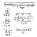
- the pad 18 houses a pair of spring loaded jaws 76 mounted for slidable engagement on a wear plate 50 for aligning the fastener, and a footrest or footpad 52 for maintaining the pad 18 against the workpiece (not shown).
- the wear plate 50 includes a main plate or planar bottom member 73 and a raised platform 72 spaced inwards of the periphery of the main plate 73, Figures 10 and 11.
- the raised platform 72 is positioned inwardly of the main plate 73 on all sides to form shoulders.
- Four spaced holes 74 extend through the main plate 73 adjacent the corners thereof for attachment to the pad 18, and a clear through bore 64 communicates with the bore 42 of the barrel to permit the fastener to pass therethrough.
- the longitudinal flanges 44 of the barrel 16 extend on either side of the raised platform 72 and are thus accommodated by the said shoulders to prevent rotation of the pad 18 with respect to the barrel 16.
- Each jaw 76 slidably ride on the platform 72 which bears the brunt of the load of the driver tool 11 and barrel assembly 12 during an installation sequence, Figure 2.
- Each jaw 76 includes an arcuate beveled entry section or recess 84 having a notch 86 at the centre thereof, Figures 12 and 13.
- the jaws 76 also include a blind recess 82 which accommodates a jaw spring 78, Figure 2.
- the jaws 76 are urged against one another by means of the jaw springs 78 positioned within the recesses 84 through fasteners 80 extending through the pad 18. In the closed position of the jaws, i.e. the extended position of the barrel assembly, the notches 86 are aligned to form an entry point for the fastener point 29, to guide the latter.
- the bottom of the pad 18 includes a recess 66 ( Figures 2 and 3) which, in the case of an insulation installation, houses a plate (not shown) through which the fastener passes for holding the insulation to a metal roof deck.
- Four magnets 68 are positioned in the corners of the recess 66 for holding a metal plate in position during installation. Where plastic plates are employed, alternate holding means are provided.
- a bearing plate 62 is connected to the pad 18 by means of fasteners 70 extending through the holes 74 of plate 73 into the pad 18.
- the footpad 52 Extending outwardly from end 53 ( Figure 2) of the workpiece pad 18 is the footpad 52.
- the footpad 52 comprises a beam 54 which splits at one end into arms 60 and which includes a depending leg 58 at the other end for resting on the workpiece.
- the arms 60 are appropriately apertured to receive a pivot pin 56 which extends through the pad 18 midway of its ends along the barrel centre line.
- the footpad 52 is thus pivotally connected to the pad 18 at its end remote from the leg 58.
- the key is the pivotal connection along the barrel centre line.
- the installation of a fastener 24 using the barrel assembly 10 is as follows. In the extended position, the driver 15 is above and out of interference with the bore in the area of opening 22 in the inner sleeve 14.
- the fastener 24, whose head 25 has a screwdriver receiving recess 27 is hand fed into the slot 20 by merely inserting the point 29 into the slot 20 and letting it slide therealong into the opening 22.
- the fastener 24 passes by gravity into the barrel bore 42 through the notch 40 and the fastener head 25 falls through the enlarged area 41.
- the movement of the fastener 24 is slightly interrupted as the fastener head 25 falls in place and the slight angular direction of the fastener 24 becomes coaxial with the barrel bore 42.
- the point 29 of the fastener 24 is guided into the aligned notches 86 of the jaws 76 by the bevelled surfaces 84.
- the pad 18 is then checked for proper position on the workpiece and the operator's foot is positioned on the footpad 52.
- the inner sleeve 14 and the barrel 16 start to retract and the screwdriver end of the driver 15 is able to engage the slot 27 of the fastener 24.
- the continued application of force pushes the fastener 24 through the jaws 76 which slidably retract along the raised platform 72 of the wear plate 50 as the fastener 24 is driven along the beveled surfaces 84.
- the barrel 16 has retracted into the inner sleeve 14 which in turn has retracted within the outer sleeve 12.
- the barrel assembly 10 and the driver tool 11 are removed and the spring 26 urges the respective sleeves and barrel into the extended position with the driver 15 out of interference with the opening 22 and the barrel assembly 10 is ready for another fastener.
- the above tool provides many advantages. Since the jaws 76 are integral with the workpiece pad 18, the pad 18 cannot be removed by the installer, thus assuring better alignment.
- the barrel assembly 10 is substantially shorter than one which includes a tube feed. Any bowed fastener 24 is immediately detected as it hangs up in the entrant means 20 and it can be easily removed by hand. The downward thrust of the tool is taken up in large measure by the wear plate 50, thus minimizing the number of components which must be specially treated for wear. Moreover, the footpad 52 keeps everything in place during installation to ensure proper alignment and positioning.
Landscapes
- Engineering & Computer Science (AREA)
- Mechanical Engineering (AREA)
- Portable Nailing Machines And Staplers (AREA)
Claims (12)
Applications Claiming Priority (2)
| Application Number | Priority Date | Filing Date | Title |
|---|---|---|---|
| US06/124,524 US4295394A (en) | 1980-02-25 | 1980-02-25 | Installation tool barrel assembly |
| US124524 | 1980-02-25 |
Publications (2)
| Publication Number | Publication Date |
|---|---|
| EP0034679A1 EP0034679A1 (de) | 1981-09-02 |
| EP0034679B1 true EP0034679B1 (de) | 1984-02-01 |
Family
ID=22415372
Family Applications (1)
| Application Number | Title | Priority Date | Filing Date |
|---|---|---|---|
| EP80303941A Expired EP0034679B1 (de) | 1980-02-25 | 1980-11-05 | Gehäuse für ein Befestigungselemententreibwerkzeug |
Country Status (4)
| Country | Link |
|---|---|
| US (1) | US4295394A (de) |
| EP (1) | EP0034679B1 (de) |
| CA (1) | CA1137701A (de) |
| DE (1) | DE3066426D1 (de) |
Families Citing this family (18)
| Publication number | Priority date | Publication date | Assignee | Title |
|---|---|---|---|---|
| ZA871322B (en) * | 1987-02-24 | 1987-10-28 | Alexander Else Frederick | Screw holder |
| US4809568A (en) * | 1988-04-21 | 1989-03-07 | Demby Industries, Inc. | Barrel assembly for installation tool and method of installation |
| AUPM948894A0 (en) * | 1994-11-17 | 1994-12-08 | Ramset Fasteners (Aust.) Pty. Limited | Power actuated fastening tool |
| US5791207A (en) * | 1997-02-14 | 1998-08-11 | Ahdoot; Ned M. | Fastener feeder |
| US6622596B2 (en) * | 2000-03-29 | 2003-09-23 | Textron Inc. | Spring loaded drive gun |
| US6729522B2 (en) * | 2001-01-26 | 2004-05-04 | Illinois Tool Works Inc. | Fastener driving tool having improved bearing and fastener guide assemblies |
| US11433511B2 (en) * | 2013-03-15 | 2022-09-06 | Omg, Inc. | Dual positionable fastener installation tool adaptor |
| US9969068B2 (en) | 2013-03-15 | 2018-05-15 | Omg, Inc. | Fastener installation tool for roof truss framing and construction system |
| US11975424B2 (en) | 2013-03-15 | 2024-05-07 | Omg, Inc. | Multiple entry angle adaptor with locator for fastener installation tool |
| US10603768B2 (en) | 2013-03-15 | 2020-03-31 | Omg, Inc. | Installation tool/fastener system for roof truss framing and construction |
| US10406659B2 (en) | 2013-03-15 | 2019-09-10 | Omg, Inc. | Flush position indicator for fastener installation tool for roof truss framing and construction system |
| US10018215B2 (en) | 2013-03-15 | 2018-07-10 | Handy & Harman | Fastener for installation tool for roof truss framing and construction system |
| US10124470B2 (en) | 2013-03-15 | 2018-11-13 | Omg, Inc. | Fastener installation tool adaptor |
| CA2903804C (en) * | 2013-03-15 | 2019-04-23 | Handy & Harman | Fastener installation tool for roof truss framing and construction system |
| DE102013112323A1 (de) * | 2013-11-08 | 2015-05-13 | Wera-Werk Hermann Werner Gmbh & Co. Kg | Schraubwerkzeug mit Einpresskraftbegrenzung |
| SE542013C2 (en) * | 2018-01-18 | 2020-02-11 | Eurospacers Ab | Mounting device for insulation holders |
| US11920678B1 (en) * | 2023-02-13 | 2024-03-05 | GM Global Technology Operations LLC | Parking pawl pin bore support |
| EP4700188A1 (de) * | 2024-08-20 | 2026-02-25 | SFS Group International AG | Setzgerät |
Family Cites Families (6)
| Publication number | Priority date | Publication date | Assignee | Title |
|---|---|---|---|---|
| US1945741A (en) * | 1933-02-09 | 1934-02-06 | Winfleld E Gray | Screw driver |
| US2327074A (en) * | 1940-07-26 | 1943-08-17 | Floyd C Snyder | Chuck |
| US2845968A (en) * | 1957-01-23 | 1958-08-05 | Anthony J Luber | Power driven screw driver having screw holding means |
| DE1917799U (de) * | 1965-04-15 | 1965-06-10 | Feldpausch & Co | Schrauber. |
| US3656520A (en) * | 1970-03-30 | 1972-04-18 | Fmc Corp | Power tool and automatic feed therefor |
| US3973605A (en) * | 1975-09-16 | 1976-08-10 | Textron, Inc. | Driving tool barrel assembly |
-
1980
- 1980-02-25 US US06/124,524 patent/US4295394A/en not_active Expired - Lifetime
- 1980-10-15 CA CA000362469A patent/CA1137701A/en not_active Expired
- 1980-11-05 EP EP80303941A patent/EP0034679B1/de not_active Expired
- 1980-11-05 DE DE8080303941T patent/DE3066426D1/de not_active Expired
Also Published As
| Publication number | Publication date |
|---|---|
| DE3066426D1 (en) | 1984-03-08 |
| EP0034679A1 (de) | 1981-09-02 |
| US4295394A (en) | 1981-10-20 |
| CA1137701A (en) | 1982-12-21 |
Similar Documents
| Publication | Publication Date | Title |
|---|---|---|
| EP0034679B1 (de) | Gehäuse für ein Befestigungselemententreibwerkzeug | |
| CA1043138A (en) | Installation tool apparatus | |
| JPS6035592Y2 (ja) | 締付部材駆動工具連結用バレル装置 | |
| EP0805736B1 (de) | Schrauben-band mit überlappenden unterlegscheiben, und verfahren und vorrichtung zu deren anbringung | |
| US4809568A (en) | Barrel assembly for installation tool and method of installation | |
| US3930297A (en) | Fastener feed apparatus and method | |
| US5722805A (en) | Drill bit adaptor tool | |
| US4674367A (en) | Apparatus for inserting and removing screws | |
| US5193729A (en) | Fastener-driving tool assembly with improved fastener-loading features | |
| US5297713A (en) | Rear load magazine assembly | |
| EP0187498B1 (de) | Vorrichtung zum Halten einer Schraube oder dgl. | |
| US5437404A (en) | Adjustable shear block assembly | |
| KR100200383B1 (ko) | 나선형 코일 삽입체용의 개선된 설치 공구 | |
| US5335409A (en) | Screwdriver including a handle with an O-ring therein for retaining a removable bit and method of assembly therefor | |
| CA2051728C (en) | Fastener having recessed, non-circular head, and fastener-driving tool | |
| CA2455108C (en) | Threaded insert tool | |
| US5138914A (en) | Scroll saw wrench | |
| EP0246206B1 (de) | Nagelzuführvorrichtung | |
| US4706868A (en) | Panel fastener assembly system | |
| EP0202103B1 (de) | Zuführungsbaugruppe für Befestiger mit Eintreibgerät | |
| GB2088264A (en) | Screwing tool attachment | |
| GB2098904A (en) | Automatic stud driving tool | |
| CA1058429A (en) | Installation tool apparatus | |
| GB2170744A (en) | Screwing guide pilot | |
| CA2324742C (en) | Fastener retaining nosepiece for screwdriver |
Legal Events
| Date | Code | Title | Description |
|---|---|---|---|
| PUAI | Public reference made under article 153(3) epc to a published international application that has entered the european phase |
Free format text: ORIGINAL CODE: 0009012 |
|
| AK | Designated contracting states |
Designated state(s): CH DE FR GB SE |
|
| 17P | Request for examination filed |
Effective date: 19811015 |
|
| GRAA | (expected) grant |
Free format text: ORIGINAL CODE: 0009210 |
|
| AK | Designated contracting states |
Designated state(s): CH DE FR GB LI SE |
|
| REF | Corresponds to: |
Ref document number: 3066426 Country of ref document: DE Date of ref document: 19840308 |
|
| ET | Fr: translation filed | ||
| PGFP | Annual fee paid to national office [announced via postgrant information from national office to epo] |
Ref country code: FR Payment date: 19841120 Year of fee payment: 5 Ref country code: DE Payment date: 19841120 Year of fee payment: 5 |
|
| PLBE | No opposition filed within time limit |
Free format text: ORIGINAL CODE: 0009261 |
|
| STAA | Information on the status of an ep patent application or granted ep patent |
Free format text: STATUS: NO OPPOSITION FILED WITHIN TIME LIMIT |
|
| PGFP | Annual fee paid to national office [announced via postgrant information from national office to epo] |
Ref country code: CH Payment date: 19841224 Year of fee payment: 5 |
|
| PGFP | Annual fee paid to national office [announced via postgrant information from national office to epo] |
Ref country code: SE Payment date: 19841231 Year of fee payment: 5 |
|
| 26N | No opposition filed | ||
| PG25 | Lapsed in a contracting state [announced via postgrant information from national office to epo] |
Ref country code: SE Effective date: 19861106 |
|
| PG25 | Lapsed in a contracting state [announced via postgrant information from national office to epo] |
Ref country code: LI Effective date: 19861130 Ref country code: CH Effective date: 19861130 |
|
| GBPC | Gb: european patent ceased through non-payment of renewal fee | ||
| PG25 | Lapsed in a contracting state [announced via postgrant information from national office to epo] |
Ref country code: FR Free format text: LAPSE BECAUSE OF NON-PAYMENT OF DUE FEES Effective date: 19870731 |
|
| REG | Reference to a national code |
Ref country code: CH Ref legal event code: PL |
|
| PG25 | Lapsed in a contracting state [announced via postgrant information from national office to epo] |
Ref country code: DE Effective date: 19870801 |
|
| REG | Reference to a national code |
Ref country code: FR Ref legal event code: ST |
|
| PG25 | Lapsed in a contracting state [announced via postgrant information from national office to epo] |
Ref country code: GB Effective date: 19881118 |
|
| EUG | Se: european patent has lapsed |
Ref document number: 80303941.1 Effective date: 19870901 |