EP0034964A2 - Verfahren zum Feststellen der Fortbewegung eines Punktes im Verhältnis zu einem Referenzpunkt und Verwendung beim Feststellen des Unterdrucks eines Reifens und/oder der Masse und Zentrierung bei Flugzeugen - Google Patents
Verfahren zum Feststellen der Fortbewegung eines Punktes im Verhältnis zu einem Referenzpunkt und Verwendung beim Feststellen des Unterdrucks eines Reifens und/oder der Masse und Zentrierung bei Flugzeugen Download PDFInfo
- Publication number
- EP0034964A2 EP0034964A2 EP81400196A EP81400196A EP0034964A2 EP 0034964 A2 EP0034964 A2 EP 0034964A2 EP 81400196 A EP81400196 A EP 81400196A EP 81400196 A EP81400196 A EP 81400196A EP 0034964 A2 EP0034964 A2 EP 0034964A2
- Authority
- EP
- European Patent Office
- Prior art keywords
- bar
- displacement
- point
- landing gear
- relative
- Prior art date
- Legal status (The legal status is an assumption and is not a legal conclusion. Google has not performed a legal analysis and makes no representation as to the accuracy of the status listed.)
- Withdrawn
Links
Images

Classifications
-
- G—PHYSICS
- G01—MEASURING; TESTING
- G01G—WEIGHING
- G01G19/00—Weighing apparatus or methods adapted for special purposes not provided for in the preceding groups
- G01G19/02—Weighing apparatus or methods adapted for special purposes not provided for in the preceding groups for weighing wheeled or rolling bodies, e.g. vehicles
- G01G19/07—Weighing apparatus or methods adapted for special purposes not provided for in the preceding groups for weighing wheeled or rolling bodies, e.g. vehicles for weighing aircraft
-
- B—PERFORMING OPERATIONS; TRANSPORTING
- B60—VEHICLES IN GENERAL
- B60C—VEHICLE TYRES; TYRE INFLATION; TYRE CHANGING; CONNECTING VALVES TO INFLATABLE ELASTIC BODIES IN GENERAL; DEVICES OR ARRANGEMENTS RELATED TO TYRES
- B60C23/00—Devices for measuring, signalling, controlling, or distributing tyre pressure or temperature, specially adapted for mounting on vehicles; Arrangement of tyre inflating devices on vehicles, e.g. of pumps or of tanks; Tyre cooling arrangements
- B60C23/06—Signalling devices actuated by deformation of the tyre, e.g. tyre mounted deformation sensors or indirect determination of tyre deformation based on wheel speed, wheel-centre to ground distance or inclination of wheel axle
-
- B—PERFORMING OPERATIONS; TRANSPORTING
- B64—AIRCRAFT; AVIATION; COSMONAUTICS
- B64C—AEROPLANES; HELICOPTERS
- B64C25/00—Alighting gear
-
- G—PHYSICS
- G01—MEASURING; TESTING
- G01B—MEASURING LENGTH, THICKNESS OR SIMILAR LINEAR DIMENSIONS; MEASURING ANGLES; MEASURING AREAS; MEASURING IRREGULARITIES OF SURFACES OR CONTOURS
- G01B7/00—Measuring arrangements characterised by the use of electric or magnetic techniques
- G01B7/16—Measuring arrangements characterised by the use of electric or magnetic techniques for measuring the deformation in a solid, e.g. by resistance strain gauge
Definitions
- the present invention relates to devices for detecting the displacement of at least one point relative to a frame of reference, more particularly applicable in systems for determining the under-inflated state of tires and / or of centering mass for aerodynes equipped main landing gear with balance wheel, for example carrying a pair of wheels fitted with diabolo tires and arranged in parallel planes on either side of the balance wheel.
- the object of the present invention is to overcome this drawback and to provide a device making it possible to detect, simply but precisely, the displacement of at least one point of a determined body, relative to a frame of reference.
- the subject of the present invention is more particularly a device for detecting the displacement of an element relative to a frame of reference, characterized in that it comprises a feedback bar, means for connecting a first end of said bar with said element, the other second end of said bar being able to cooperate with means for determining the displacement of this second end relative to said frame of reference.
- the means for determining the displacement of this second end comprise at least one sensor comprising at least two active parts, one being located on said feedback bar, the other fixed relative to said reference frame.
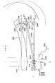
- This device comprises a bar 105 preferably cylindrical, made of a rigid, but light material such as for example aluminum alloy.
- This bar 105 is linked at its end 111 to the pendulum 101 by a link such as for example a ball joint 106 secured to a fixing lug 107 which will be secured to the pendulum preferably in this application in the vicinity of its part 108 which supports the axle 102 wheels.
- this ball joint 106 essentially allows the axis to pivot around a point defined substantially in the figure at 109 on the axis 110, but absolutely not around this axis 110.
- this ball joint 106 is equivalent to a universal ball joint in which a degree of freedom has been removed; the one that prevents the bar 105 from turning on itself.
- This bar cooperates substantially with its other end mite 112 with a frame of reference which, in this exemplary embodiment will be linked to the leg 113, supporting the pendulum 101.
- This bar cooperates with this reference system by a ball joint 114 which has been represented schematically by a part 115 fixed on the leg 113 or possibly. Lement on the pendulum 101 near the leg, in a place which could be considered with a good approximation as relatively fixed with respect to the leg 113 or the body of the aircraft.
- this ball joint advantageously allows translation of the rod 105 in the body of the ball joint 114.
- the end 112 of the bar 105 substantially exceeds the ball joint 114 to emerge from the latter at 116 in an opposite part, to that fixed by the tab 107 on the balance 101, relative to the ball 114.
- This part 116 cooperates respectively with three sensors 117, 118, 119, which make it possible to determine the position of this end part 116 of the bar.
- Each sensor comprises an arm 120, 121, 122, fixed on the end 116 of the bar 105, and terminated by a so-called target part 123, 124, 125, formed of a relatively flat pallet capable of cooperating with a detection member or probe 126, 127, 128, placed opposite this pallet, and which is fixed relative to the frame of reference, that is to say in this embodiment, to the leg 113 by means of the part 115.
- the three sensors in their structure defined above are arranged in a determined manner relative to the rest position of the bar, as defined below.
- the axis 0 is preferably chosen perpendicular to the plane in which the probability of displacement, for example of the pendulum is greatest, and finally, consequently, the axis 0 z is deduced from the other two and is therefore in the plane mentioned. just above.
- the pallet 123 is centered on the axis 0 y and, so that its flat surface is located in the plane 0 y ', 0 x
- the pallet 124 is located on the axis 0 z 'and so that its plane surface is in the plane O z', 0 y
- the pallet 125 is centered on the axis 0 y and so that its plane surface either in the plane 0 y, O zo
- the detection members 126, 127 and 128 are arranged relative to the pallets in accordance with the detection requirements, these being represented schematically by cylinders perpendicular to the plane of the pallets when they are in the bar position at rest.
- sensors could be, for example inductive or differential transformer sensors like those sold by VIBRO METER - Ref. 102, which can deliver a preferably electrical signal at the output, which is a function of the average distance, separating the surface of the pallet from the input face of each detection member.
- each output 129, 130, 131, of the detection members 126, 127, 128, is connected to the input 132 of an electronic computing circuit 133 which may receive other signals 134, 135, possibly originating from other measurement and detection systems, which can deliver usable information at its output 136, in particular in the case of aerodynes, by pilots to determine for example the under-inflation state of one of the tires of a undercarriage .
- the function of the device is as follows. In the rest position of the bar 105 and therefore of the pendulum 101, the pallets 123, 124 and 125 are in the planes defined above. To facilitate the understanding of the operation, four separate cases will be considered successively and all the others will then be able to deduce therefrom. In a first case, it is assumed that the pendulum is deformed so that it bends while lifting while remaining in the plane 0 z; 0 x.
- the pendulum 101 by the tab 107 pulls on the end 111 of the bar 105.
- This bar by the ball 114 pivots around the point O without deformation, and drives in the same rotation, all three sensorso In the hypothesis chosen, this rotation is equivalent to a rotation around the axis y'y.
- the average distance of the respective pallets 123 and 125 remains the same with respect to their detector members 126 and 128, and no significant signal is then delivered by these members.
- the bar drives the arm 121 and the pallet 124 in a movement which tends to bring the pallet 124 closer to the member 127. This will deliver a corresponding signal which will be interpreted by the computing circuit 133.
- the pendulum is subjected to a force which tends to twist it, while remaining in a plane parallel to the plane (y'oy, x'ox).
- the bar 105 is then subjected to a rotation around the point O, but also around the axis zz '.
- the pallets 123 and 124 remain substantially at the same distance, real or average, from their respective detection members 126 and 127, since the pallet 123 remains in the plane y'ox and that the pallet 124 rotates around the 'oz axis'.
- the pallet 125 approaches or moves away in the direction of the deformation of the pendulum 101 and the member 128 delivers a corresponding signal which will be very easily interpreted by the calculation circuit 133.
- the pendulum undergoes a torsion, which happens when one of the tires like 104 is deflated.
- the bar 105 as it is fixed by the tab 107, undergoes at least one rotation which, in a first approximation, can be compared to a rotation around substantially its axis x'x, with another rotation around from point O.
- the pallet 123 will, in the direction of the torsion of the pendulum 101, move away from or approach its detection member 126 which will deliver a corresponding signal, at its output 129, representative of the torsion of the pendulum .
- the calculation circuit will be able to take into account all the signals delivered to the outputs 129, 130 and 131, and to develop des.informations representative of the real deformation for example of the pendulum and the technicians will be able to draw the necessary consequences.
- the device described above gives good results and the electronic circuit 133 can, as a function of the information received from the various probes, communicate the position of the end 116 of the bar 105.
- the device comprises a bar 205 associated with three sensors 217, 218 and 219 formed by a target 224 and a probe 227, in the same way as according to sensors 117, 118 and 119.
- This bar is mounted on a first ball joint 214 linked to the frame of reference 0 x, y, z, but this ball joint does not allow a translation, this being prevented by any means such as for example two plates 253 and 254 which are integral with the bar which however allow rotation on it- even.
- the bar comprises connecting means comprising a ball joint 206 and a rod 250 rotatably mounted with a single degree of freedom in a plane on two axes 251 and 252 respectively on the ball joint 206 and on the pendulum. These two axes are perpendicular to the plane mentioned above which is chosen, in fact the one in which the pendulum bending can be carried out.
- the rod 250 constitutes a rigid connection between the balance, 201 and the end 211 of the bar 2050
- the pendulum 201 and the bar 205 are shown in dotted lines in a normal rest position, and in solid lines the pendulum and the bar after bending in a plane.
- the attachment point 208 of the rod 250 on the balance pulls on the bar to make it undergo a rotation ⁇ around the point 0 of the frame of reference, but, due to the configuration particular of the ball joint 214, the bar does not translate on itself.
- the link it pivots by an angle ⁇ around the two axes 251 and 252 because the attachment point 208 moves away from the point O in this configuration where the bar is below the balance.
- the device described above finds particularly advantageous applications, in particular in the case of the detection of the under-inflated state of the tires of an aerodyne.
- the feedback bar is fixed to a place on the landing gear as close as possible to the tires, while its other end is brought to a place on the train which, due to its structure, suffers little deformation. when, for example, one of the tires is not inflated enough and / or even burst.
- the deformation undergone by the train, and in particular the part close to the tires, is analyzed by the signals delivered by the sensors and a variation in the value of the state of inflation of tires is deduced therefrom.
- the device makes it possible to detect and possibly even measure the mass and the centering of the total masses of an aerodyne.
- the deformations of the landing gear are indicative of this on-board mass and, consequently, of the total mass of this aerodyne.
Landscapes
- Engineering & Computer Science (AREA)
- Physics & Mathematics (AREA)
- General Physics & Mathematics (AREA)
- Aviation & Aerospace Engineering (AREA)
- Mechanical Engineering (AREA)
- Length Measuring Devices With Unspecified Measuring Means (AREA)
- Tires In General (AREA)
- Measurement Of Length, Angles, Or The Like Using Electric Or Magnetic Means (AREA)
- Measurement Of Force In General (AREA)
Applications Claiming Priority (4)
| Application Number | Priority Date | Filing Date | Title |
|---|---|---|---|
| FR8003701A FR2476017A1 (fr) | 1980-02-20 | 1980-02-20 | Installation et dispositif de detection de l'etat sous-gonfle de pneumatiques et/ou de masse et de centrage pour aerodynes |
| FR8003701 | 1980-02-20 | ||
| FR8013050 | 1980-06-12 | ||
| FR8013050A FR2484653A1 (fr) | 1980-06-12 | 1980-06-12 | Dispositif de detection du deplacement d'au moins un point par rapport a un referentiel |
Publications (2)
| Publication Number | Publication Date |
|---|---|
| EP0034964A2 true EP0034964A2 (de) | 1981-09-02 |
| EP0034964A3 EP0034964A3 (de) | 1981-09-09 |
Family
ID=26221615
Family Applications (1)
| Application Number | Title | Priority Date | Filing Date |
|---|---|---|---|
| EP81400196A Withdrawn EP0034964A3 (de) | 1980-02-20 | 1981-02-09 | Verfahren zum Feststellen der Fortbewegung eines Punktes im Verhältnis zu einem Referenzpunkt und Verwendung beim Feststellen des Unterdrucks eines Reifens und/oder der Masse und Zentrierung bei Flugzeugen |
Country Status (2)
| Country | Link |
|---|---|
| US (1) | US4388763A (de) |
| EP (1) | EP0034964A3 (de) |
Cited By (1)
| Publication number | Priority date | Publication date | Assignee | Title |
|---|---|---|---|---|
| EP0054453A1 (de) * | 1980-11-27 | 1982-06-23 | AEROSPATIALE Société Nationale Industrielle | Vorrichtung zum Feststellen des Unterdruckes eines Flugzeuglandegestellreifens |
Families Citing this family (3)
| Publication number | Priority date | Publication date | Assignee | Title |
|---|---|---|---|---|
| CN100504335C (zh) * | 2007-04-10 | 2009-06-24 | 高世江 | 轮胎防爆监测报警器 |
| GB2485803B (en) | 2010-11-24 | 2013-02-06 | Messier Dowty Ltd | Mechanical position indicator |
| CN108706056A (zh) * | 2016-12-12 | 2018-10-26 | 恒大法拉第未来智能汽车(广东)有限公司 | 一种用于轿车的爆胎稳定系统和包括其的轿车 |
Family Cites Families (9)
| Publication number | Priority date | Publication date | Assignee | Title |
|---|---|---|---|---|
| US2587628A (en) * | 1949-01-24 | 1952-03-04 | Harold B King | Load stroke indicator |
| FR1355098A (fr) * | 1962-06-08 | 1964-03-13 | Cleveland Pneumatic Ind | Installation pour la détermination du poids et du centre de gravité d'un avion |
| FR1351078A (fr) * | 1963-03-11 | 1964-01-31 | Dispositif de transmission de forces, en particulier pour instruments de mesure sur des véhicules terrestres ou aériens | |
| FR1520152A (fr) * | 1966-08-22 | 1968-04-05 | Pneumo Dynamics Corp | Système servant à indiquer le poids et la position du centre de gravité d'un avion |
| US3370296A (en) * | 1967-02-23 | 1968-02-20 | Samuel W. Greenberg | Animal activity recorder |
| CH485912A (fr) * | 1969-01-24 | 1970-02-15 | Matisa Materiel Ind Sa | Procédé de mesure du dévers d'une voie ferrée et dispositif pour sa mise en oeuvre |
| US3590633A (en) * | 1970-03-09 | 1971-07-06 | Maschf Augsburg Nuernberg Ag | Stress measuring of rotating bodies |
| US3707270A (en) * | 1970-11-30 | 1972-12-26 | Blh Electronics | Wear sleeve-transducer combination for aircraft landing gear |
| US3845919A (en) * | 1974-01-07 | 1974-11-05 | Boeing Co | Landing gear truck pitch damping |
-
1981
- 1981-02-09 EP EP81400196A patent/EP0034964A3/de not_active Withdrawn
- 1981-02-17 US US06/234,875 patent/US4388763A/en not_active Expired - Fee Related
Cited By (1)
| Publication number | Priority date | Publication date | Assignee | Title |
|---|---|---|---|---|
| EP0054453A1 (de) * | 1980-11-27 | 1982-06-23 | AEROSPATIALE Société Nationale Industrielle | Vorrichtung zum Feststellen des Unterdruckes eines Flugzeuglandegestellreifens |
Also Published As
| Publication number | Publication date |
|---|---|
| EP0034964A3 (de) | 1981-09-09 |
| US4388763A (en) | 1983-06-21 |
Similar Documents
| Publication | Publication Date | Title |
|---|---|---|
| CA3005505C (fr) | Train d'atterrissage muni d'un dispositif embarque de mesure de charge pour un aeronef, et aeronef | |
| FR2543678A1 (fr) | Dispositif de mesure de poids et appareil de mesure de la poussee developpee par l'aile tournante d'un helicoptere | |
| EP3357811B1 (de) | Fahrwerk eines luftfahrzeugs | |
| FR2986322A1 (fr) | Dispositif embarque de mesure de la masse et de la position du centre de gravite d'un aeronef | |
| FR2716717A1 (fr) | Capteur de force de roue, et appareils de détection de position angulaire et d'angle de direction d'une roue. | |
| FR2812356A1 (fr) | Roulement comprenant au moins une zone de deformation elastique et ensemble de freinage le comprenant | |
| EP3000729B1 (de) | Fahrwerk eines luftfahrzeugs | |
| WO2016193484A1 (fr) | Dispositif de mesure de pression à fiabilité améliorée et procédé de calibrage associé | |
| FR2862382A1 (fr) | Systeme capteur de couple absolu de torsion et module le comprenant | |
| EP0059295A1 (de) | Zelle zum Messen einer radial wirkenden Kraft | |
| EP1053160B1 (de) | Lenkradskelett mit angesetztem oder integriertem drehmomentsensor für eine fahrzeuglenkung | |
| FR2531219A1 (fr) | Dispositif de detection d'une pression de pneumatique faible | |
| EP0863451B1 (de) | Methode und Einrichtung zur Bestätigung der Kohärenz der Messungen einer Einfallswinkelsonde | |
| FR3012222B1 (fr) | Procede et dispositif pour la mesure de l'incidence d'un aeronef | |
| FR2531218A1 (fr) | Dispositif de detection d'une pression faible de pneumatique | |
| FR2520870A1 (fr) | Dispositif permettant de mesurer la charge repartie sur les moyens de roulement d'un train d'atterrissage d'un aeronef | |
| CA2540255A1 (fr) | Dispositif et procede de determination du poids et/ou d`une grandeur caracteristique du centrage d`un aeronef | |
| EP3702271B1 (de) | Motorisiertes fahrwerk und luftfahrzeug | |
| FR2484653A1 (fr) | Dispositif de detection du deplacement d'au moins un point par rapport a un referentiel | |
| EP0189721B1 (de) | Verfahren und Vorrichtung zur Messung des Einschlagwinkels eines Kraftfahrzeugvorderrades | |
| EP4413321A1 (de) | Vorrichtung zur messung einer linearen position | |
| FR2564582A1 (fr) | Dispositif embarque de controle de la charge d'un avion | |
| CA3056459C (fr) | Atterrisseur a balancier motorise et aeronef | |
| FR2487069A1 (fr) | Procede et dispositif pour la mesure d'au moins une composante des efforts exerces sur une poutre | |
| EP4355655B1 (de) | Landegestell ausgerüstet mit einem formsensor |
Legal Events
| Date | Code | Title | Description |
|---|---|---|---|
| PUAI | Public reference made under article 153(3) epc to a published international application that has entered the european phase |
Free format text: ORIGINAL CODE: 0009012 |
|
| PUAL | Search report despatched |
Free format text: ORIGINAL CODE: 0009013 |
|
| AK | Designated contracting states |
Designated state(s): DE GB |
|
| AK | Designated contracting states |
Designated state(s): DE GB |
|
| STAA | Information on the status of an ep patent application or granted ep patent |
Free format text: STATUS: THE APPLICATION IS DEEMED TO BE WITHDRAWN |
|
| 18D | Application deemed to be withdrawn |
Effective date: 19820816 |
|
| RIN1 | Information on inventor provided before grant (corrected) |
Inventor name: VEAUX, JACQUES Inventor name: MASCLET, JEAN |