EP0035306A2 - Procédé et appareil pour le liage circonférentiel d'un rouleau à axe horizontal - Google Patents
Procédé et appareil pour le liage circonférentiel d'un rouleau à axe horizontal Download PDFInfo
- Publication number
- EP0035306A2 EP0035306A2 EP81200213A EP81200213A EP0035306A2 EP 0035306 A2 EP0035306 A2 EP 0035306A2 EP 81200213 A EP81200213 A EP 81200213A EP 81200213 A EP81200213 A EP 81200213A EP 0035306 A2 EP0035306 A2 EP 0035306A2
- Authority
- EP
- European Patent Office
- Prior art keywords
- binding
- coil
- head
- arm
- axis
- Prior art date
- Legal status (The legal status is an assumption and is not a legal conclusion. Google has not performed a legal analysis and makes no representation as to the accuracy of the status listed.)
- Granted
Links
Images
Classifications
-
- B—PERFORMING OPERATIONS; TRANSPORTING
- B65—CONVEYING; PACKING; STORING; HANDLING THIN OR FILAMENTARY MATERIAL
- B65B—MACHINES, APPARATUS OR DEVICES FOR, OR METHODS OF, PACKAGING ARTICLES OR MATERIALS; UNPACKING
- B65B27/00—Bundling particular articles presenting special problems using string, wire, or narrow tape or band; Baling fibrous material, e.g. peat, not otherwise provided for
- B65B27/06—Bundling coils of wire or like annular objects
-
- B—PERFORMING OPERATIONS; TRANSPORTING
- B65—CONVEYING; PACKING; STORING; HANDLING THIN OR FILAMENTARY MATERIAL
- B65B—MACHINES, APPARATUS OR DEVICES FOR, OR METHODS OF, PACKAGING ARTICLES OR MATERIALS; UNPACKING
- B65B13/00—Bundling articles
- B65B13/02—Applying and securing binding material around articles or groups of articles, e.g. using strings, wires, strips, bands or tapes
- B65B13/04—Applying and securing binding material around articles or groups of articles, e.g. using strings, wires, strips, bands or tapes with means for guiding the binding material around the articles prior to severing from supply
- B65B13/08—Single guide or carrier for the free end of material movable part-away around articles from one side only
Definitions
- the present invention relates to a method for circumferentially binding a coil having an axis extending horizontally and binding apparatus for use in the method.
- an elongate binding element in the form of a length of binding material such as for example a binding strip is laid around the circumference of the coil and its ends are fastened together.
- the coil has its axis extending horizontally, we do not mean that the invention is restricted to coils whose axis is precisely level. We intend the term to cover any coil which is supported lying on its side, not on its end.
- the invention is especially applicable to the binding of coils of steel strip, but is not restricted to this use.
- the binding of such coils has generally been done manually which, as described below; is an uncomfortable and even hazardous operation.
- the coil being large, awkward positioning of the body is required, in order to pass a binding strip around it.
- NL 70.06235 briefly describes a device which apparently contains a channel along which the binding strip is passed so as to encircle the coil.
- FR 2 024 187 illustrates a machine for binding stacks of newspapers, in which a swinging.,arm carries string around the stack.
- the object of the present invention is to relieve the difficulties, in the form of an awkward position of the body and low reliability encountered during manual binding of large coils.
- the present invention as claimed is intended to provide a remedy.
- the binding element can be easily secured by the operator, for example when a strip is used as the binding, by sliding a seal over one part of the strip and by stretching and sealing the strip with a known stretching and sealing device.
- the bound coil can be transported vertically, for example by means of an overhead crane, or horizontally, for example with the aid of a fork-lift truck.
- the advantage of the process according to the present invention are that it is no longer necessary for the operator to bend down to insert and pick up the binding element and that increased reliability is achieved in that the coil can now be bound by the operator who remains at one side, so that, as will be described in further detail below, it is no longer necessary for the operator to cross the coil delivery conveyor.
- the time needed for binding is shorter because, even in the case of small coils, no more binding is delivered than is strictly necessary.
- the binding arm can be brought to a rest position in which the coil can be lifted vertically by a crane, since there is no obstacle above the coil.
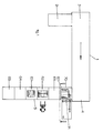
- Figure 1 shows a stretcher leveller for cold-rolled steel strip.
- the strip is delivered by the feeding conveyor 2 in the form of coils which are then uncoiled at 3.
- the coil is transported by a delivery conveyor 5 which includes a coil lifting carriage 9 (see Figure 2), extending beneath the coiling station, by means of which the coil is transferred to a binding station 60.
- the coil which is lying on saddles 23, is bound.
- the coil can be transferred by the coil lifting carriage 9 to one of positions 61 to 65, being rotated about a vertical axis through a quarter of a turn.
- the coils are removed either from positions 60 to 65 by means of an overhead crane or from position 61 to 65 with a fork-lift truck.
- the usual coil dimensions are: width 600 to 1500 mm and diameter 1000 to 1800 mm.
- a binding element e.g. a binding strip
- the operator's initial position is at 70. After being placed over the coil, the binding has to be passed back under the coil from position 71. This means that to insert the binding at 71 and to pick it up at 70, the operator has to perform awkward bending movements.
- the operator has to cross the delivery conveyor line 5, which is a deep, open trough containing the moving coil lifting carriage 9, and after inserting the binding, he has to return from position 71 to 70. These movements are uncomfortable and hazardous.
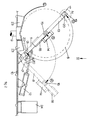
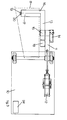
- the binding machine embodying the present invention which overcomes these difficulties, is shown in Figures 2 and 3.
- the coil 8 is shown lying on the saddles 23 (which are provided with grooves for insertion of the binding band under the coil) of the binding position 60 of the delivery conveyor 5, which is provided with the coil lifting carriage 9.
- Mounted on a base plate 10 is a swivelling main arm 11, which can be swung about its pivoting axis by the pneumatic cylinder 12.
- the end of the main arm 11 remote from the pivoting axis is attached to a rotary binding arm 13, which is pivotally mounted on the main arm so that it can be rotated by a pneumatic rotation cylinder 14 about its centre of rotation 15.
- the binding arm 13 is balanced around its centre of rotation 15 by a counter-weight 18.
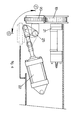
- the binding head 17 has a drive unit shown in Figure 4 and a set of hardened steel rollers 19 and 20.
- the set of steel rollers are able to run freely in one direction, for example by means of a ratchet mechanism (not shown) and can be driven in the same direction by a pneumatic motor 21.
- the lower roller 20 is mounted on a shaft 25 so that it can be retracted from the upper roller by the actuation of a locking cylinder 22 (see broken lines in Figure 4).
- the binding machine operates as follows: the operator remains standing at the left-hand side as seen in Figure 2; after a coil 8 is placed on the saddles 23 of the binding station 60 by the coil lifting carriage 9, the main arm 11 is moved from a rest position A to a working position B by the pneumatic cylinder 12 when the start command has been given. In this working position, the swinging axis of the binding arm 13 is substantially at the axis of the coil (but it may be slightly offset from the coil axis). The binding arm 13 is then swung by the rotation cylinder 14 from position C to its initial operating position D.
- the binding strip (which is for example one quarter of an inch wide) is then inserted by the operator between the free-running rollers 19 and 20 of the drive unit of transport head 17 and is thus clamped and held by the binding head.
- a further command is given, which causes the binding arm 13 to be swung from position D to its second operating position C.
- the coil 8 can be removed vertically be means of an overhead crane.
- the binding machine is in this embodiment powered by compressed air at 6 atm.
- the necessary pneumatic equipment is housed in a control cabinet 24.
- the binding cycle lends itself to control by a programmable control unit.
Landscapes
- Engineering & Computer Science (AREA)
- Mechanical Engineering (AREA)
- Basic Packing Technique (AREA)
- Manufacture Of Motors, Generators (AREA)
Priority Applications (1)
| Application Number | Priority Date | Filing Date | Title |
|---|---|---|---|
| AT81200213T ATE8762T1 (de) | 1980-02-28 | 1981-02-24 | Verfahren und vorrichtung zum umreifen der mantelflaeche einer rolle mit horizontaler achse. |
Applications Claiming Priority (2)
| Application Number | Priority Date | Filing Date | Title |
|---|---|---|---|
| NL8001196 | 1980-02-28 | ||
| NL8001196A NL8001196A (nl) | 1980-02-28 | 1980-02-28 | Werkwijze voor het binden van een liggende rol en bindmachine te gebruiken daarbij. |
Publications (3)
| Publication Number | Publication Date |
|---|---|
| EP0035306A2 true EP0035306A2 (fr) | 1981-09-09 |
| EP0035306A3 EP0035306A3 (en) | 1981-09-23 |
| EP0035306B1 EP0035306B1 (fr) | 1984-08-01 |
Family
ID=19834901
Family Applications (1)
| Application Number | Title | Priority Date | Filing Date |
|---|---|---|---|
| EP81200213A Expired EP0035306B1 (fr) | 1980-02-28 | 1981-02-24 | Procédé et appareil pour le liage circonférentiel d'un rouleau à axe horizontal |
Country Status (4)
| Country | Link |
|---|---|
| EP (1) | EP0035306B1 (fr) |
| AT (1) | ATE8762T1 (fr) |
| DE (1) | DE3165153D1 (fr) |
| NL (1) | NL8001196A (fr) |
Cited By (1)
| Publication number | Priority date | Publication date | Assignee | Title |
|---|---|---|---|---|
| DE3243003A1 (de) * | 1982-11-20 | 1984-05-24 | Hoesch Werke Ag, 4600 Dortmund | Vorrichtung zum umreifen von coils |
Family Cites Families (3)
| Publication number | Priority date | Publication date | Assignee | Title |
|---|---|---|---|---|
| US3279354A (en) * | 1965-03-17 | 1966-10-18 | Fmc Corp | Strap feeding apparatus |
| US3540765A (en) * | 1968-11-25 | 1970-11-17 | Bunn Co B | Intermittent drive for tying machine twine arm |
| GB1275602A (en) * | 1969-05-01 | 1972-05-24 | British Iron Steel Research | Packaging coils of strip material |
-
1980
- 1980-02-28 NL NL8001196A patent/NL8001196A/nl not_active Application Discontinuation
-
1981
- 1981-02-24 EP EP81200213A patent/EP0035306B1/fr not_active Expired
- 1981-02-24 AT AT81200213T patent/ATE8762T1/de not_active IP Right Cessation
- 1981-02-24 DE DE8181200213T patent/DE3165153D1/de not_active Expired
Cited By (1)
| Publication number | Priority date | Publication date | Assignee | Title |
|---|---|---|---|---|
| DE3243003A1 (de) * | 1982-11-20 | 1984-05-24 | Hoesch Werke Ag, 4600 Dortmund | Vorrichtung zum umreifen von coils |
Also Published As
| Publication number | Publication date |
|---|---|
| ATE8762T1 (de) | 1984-08-15 |
| EP0035306B1 (fr) | 1984-08-01 |
| EP0035306A3 (en) | 1981-09-23 |
| DE3165153D1 (en) | 1984-09-06 |
| NL8001196A (nl) | 1981-10-01 |
Similar Documents
| Publication | Publication Date | Title |
|---|---|---|
| US6439497B1 (en) | Method and device for mounting a winding | |
| EP0295230A1 (fr) | Dispositif de transfert de câble | |
| EP0044627A1 (fr) | Dispositif pour l'emballage d'un rouleau de tôle ou de bande métallique | |
| US6305277B1 (en) | Coil handling device | |
| EP0174066B1 (fr) | Enrouleuse | |
| US4222323A (en) | Tire bundling machine | |
| EP0035306B1 (fr) | Procédé et appareil pour le liage circonférentiel d'un rouleau à axe horizontal | |
| US5465659A (en) | Automatic machine for binding bundles of pipes or the like | |
| CN110979784A (zh) | 一种钢筋卷打捆机 | |
| EP0388761A1 (fr) | Machine de cerclage pour emballer des paquetes de tout genre et taille | |
| CN116353892B (zh) | 一种尼龙线自动绕线机 | |
| JP3129687B2 (ja) | 結束機械の上押さえ装置および結束機械 | |
| CN216736703U (zh) | 全自动打包带收卷设备 | |
| CN215787537U (zh) | 一种用于激光切管机的上料装置 | |
| US3533351A (en) | Apparatus for tightening and strapping involutely wound sheet metal coils | |
| US4586669A (en) | Method and apparatus of forming cords of hanking | |
| EP0442142B1 (fr) | Procédé pour ligaturer des emballages de treillis métalliques et machine pour la mise en oeuvre dudit procédé | |
| EP0324705A2 (fr) | Bras d'insertion de noyau à grande rotation | |
| JPS6033819A (ja) | 鋼帯コイルの溶接部等の表示紙挿入装置 | |
| AU2006100893A5 (en) | Apparatus for Forming and Packaging Flexible Ducting | |
| EP1908538B1 (fr) | Dispositif pour vriller une pièce métallique | |
| SU1181734A1 (ru) | Устройство дл съема рулонов с барабана моталки | |
| JPH0632316A (ja) | 結束装置 | |
| JPH05319407A (ja) | 金属梱包外板巻付け準備装置 | |
| JP2554578B2 (ja) | ゴムシートの自動巻取装置 |
Legal Events
| Date | Code | Title | Description |
|---|---|---|---|
| PUAI | Public reference made under article 153(3) epc to a published international application that has entered the european phase |
Free format text: ORIGINAL CODE: 0009012 |
|
| PUAL | Search report despatched |
Free format text: ORIGINAL CODE: 0009013 |
|
| 17P | Request for examination filed |
Effective date: 19810224 |
|
| AK | Designated contracting states |
Designated state(s): AT BE DE FR GB IT LU NL |
|
| AK | Designated contracting states |
Designated state(s): AT BE DE FR GB IT LU NL |
|
| RAP1 | Party data changed (applicant data changed or rights of an application transferred) |
Owner name: HOOGOVENS GROEP B.V. |
|
| GRAA | (expected) grant |
Free format text: ORIGINAL CODE: 0009210 |
|
| AK | Designated contracting states |
Designated state(s): AT BE DE FR GB IT LU NL |
|
| PG25 | Lapsed in a contracting state [announced via postgrant information from national office to epo] |
Ref country code: IT Free format text: LAPSE BECAUSE OF FAILURE TO SUBMIT A TRANSLATION OF THE DESCRIPTION OR TO PAY THE FEE WITHIN THE PRESCRIBED TIME-LIMIT;WARNING: LAPSES OF ITALIAN PATENTS WITH EFFECTIVE DATE BEFORE 2007 MAY HAVE OCCURRED AT ANY TIME BEFORE 2007. THE CORRECT EFFECTIVE DATE MAY BE DIFFERENT FROM THE ONE RECORDED. Effective date: 19840801 Ref country code: AT Effective date: 19840801 |
|
| REF | Corresponds to: |
Ref document number: 8762 Country of ref document: AT Date of ref document: 19840815 Kind code of ref document: T |
|
| REF | Corresponds to: |
Ref document number: 3165153 Country of ref document: DE Date of ref document: 19840906 |
|
| ET | Fr: translation filed | ||
| PGFP | Annual fee paid to national office [announced via postgrant information from national office to epo] |
Ref country code: DE Payment date: 19850121 Year of fee payment: 5 |
|
| PG25 | Lapsed in a contracting state [announced via postgrant information from national office to epo] |
Ref country code: LU Free format text: LAPSE BECAUSE OF NON-PAYMENT OF DUE FEES Effective date: 19850228 |
|
| PLBE | No opposition filed within time limit |
Free format text: ORIGINAL CODE: 0009261 |
|
| 26N | No opposition filed | ||
| PGFP | Annual fee paid to national office [announced via postgrant information from national office to epo] |
Ref country code: NL Payment date: 19860228 Year of fee payment: 6 |
|
| PGFP | Annual fee paid to national office [announced via postgrant information from national office to epo] |
Ref country code: LU Payment date: 19860303 Year of fee payment: 6 |
|
| BERE | Be: lapsed |
Owner name: HOOGOVENS GROEP B.V. Effective date: 19870228 |
|
| PG25 | Lapsed in a contracting state [announced via postgrant information from national office to epo] |
Ref country code: NL Effective date: 19870901 |
|
| GBPC | Gb: european patent ceased through non-payment of renewal fee | ||
| NLV4 | Nl: lapsed or anulled due to non-payment of the annual fee | ||
| PG25 | Lapsed in a contracting state [announced via postgrant information from national office to epo] |
Ref country code: FR Free format text: LAPSE BECAUSE OF NON-PAYMENT OF DUE FEES Effective date: 19871030 |
|
| PG25 | Lapsed in a contracting state [announced via postgrant information from national office to epo] |
Ref country code: DE Effective date: 19871103 |
|
| REG | Reference to a national code |
Ref country code: FR Ref legal event code: ST |
|
| PG25 | Lapsed in a contracting state [announced via postgrant information from national office to epo] |
Ref country code: GB Effective date: 19881118 |
|
| PG25 | Lapsed in a contracting state [announced via postgrant information from national office to epo] |
Ref country code: BE Effective date: 19890228 |