EP0035875A2 - Appareil et procédé d'agrandissement ou de réduction d'éléments d'image - Google Patents
Appareil et procédé d'agrandissement ou de réduction d'éléments d'image Download PDFInfo
- Publication number
- EP0035875A2 EP0035875A2 EP81300918A EP81300918A EP0035875A2 EP 0035875 A2 EP0035875 A2 EP 0035875A2 EP 81300918 A EP81300918 A EP 81300918A EP 81300918 A EP81300918 A EP 81300918A EP 0035875 A2 EP0035875 A2 EP 0035875A2
- Authority
- EP
- European Patent Office
- Prior art keywords
- image
- frequency
- size
- axis
- along
- Prior art date
- Legal status (The legal status is an assumption and is not a legal conclusion. Google has not performed a legal analysis and makes no representation as to the accuracy of the status listed.)
- Granted
Links
Images



Classifications
-
- G—PHYSICS
- G03—PHOTOGRAPHY; CINEMATOGRAPHY; ANALOGOUS TECHNIQUES USING WAVES OTHER THAN OPTICAL WAVES; ELECTROGRAPHY; HOLOGRAPHY
- G03G—ELECTROGRAPHY; ELECTROPHOTOGRAPHY; MAGNETOGRAPHY
- G03G15/00—Apparatus for electrographic processes using a charge pattern
- G03G15/04—Apparatus for electrographic processes using a charge pattern for exposing, i.e. imagewise exposure by optically projecting the original image on a photoconductive recording material
- G03G15/041—Apparatus for electrographic processes using a charge pattern for exposing, i.e. imagewise exposure by optically projecting the original image on a photoconductive recording material with variable magnification
-
- G—PHYSICS
- G06—COMPUTING OR CALCULATING; COUNTING
- G06T—IMAGE DATA PROCESSING OR GENERATION, IN GENERAL
- G06T3/00—Geometric image transformations in the plane of the image
- G06T3/40—Scaling of whole images or parts thereof, e.g. expanding or contracting
-
- H—ELECTRICITY
- H04—ELECTRIC COMMUNICATION TECHNIQUE
- H04N—PICTORIAL COMMUNICATION, e.g. TELEVISION
- H04N1/00—Scanning, transmission or reproduction of documents or the like, e.g. facsimile transmission; Details thereof
- H04N1/387—Composing, repositioning or otherwise geometrically modifying originals
- H04N1/393—Enlarging or reducing
- H04N1/3935—Enlarging or reducing with modification of image resolution, i.e. determining the values of picture elements at new relative positions
Definitions
- This invention relates to a pixel magnification/de magnification apparatus and method, and more particularly to apparatus and method for controlling the size of the image producible from pixels derived by scanning image bearing documents.
- Image scanning devices such as raster scanners permit a large variety of so called image processing functions to be accomplished on the image between the time the original document is first scanned and the time the output image or copy is produced.
- One particularly useful function is continuous minification or reduction and magnification or enlargement of the image.
- reduction of images is quite useful for document merging, two-up configurations, faster digital rotation, and the like.
- Magnification is also useful as it permits composition, filling a page with a document, etc.
- the present invention is intended to provide a remedy and, from one aspect, is characterised by a pixel control gate through which said pixels pass; clock means for generating pixel clock pulses at a maximum frequency representing maximum image size along a first axis, said pixel clock pulses being output to said control gate to control enablement of said control gate; a fractional multiplier for selectively reducing the frequency of said pixel clock pulses from said maximum to a minimum frequency representing minimum image size along said first axis; first control means for varying the multiplication ratio of said multiplier between said maximum and minimum frequencies to thereby vary the frequency of the pixel clock signals to said control gate and accordingly the rate at which pixels pass through said control gate; and second control means for varying the speed at which documents are raster scanned to thereby vary the rate at which pixels are produced and accordingly the size of the image along a second axis.
- the invention is characterised by the steps of controlling the speed at which an image bearing document is scanned to produce image pixels at a rate which provides an image of selected size along a first axis; clocking the image pixels with a pixel clock; generating new pixel clock pulses at a maximum frequency corresponding to the maximum image size along a second axis; selectively reducing the frequency of the new pixel clock pulses to thereby reduce the size of the image producible by the image pixels along said second axis to a selected size; and clocking the image pixels with said new pixel clock pulses.
- Scanner 12 includes a frame or housing 18, having base 20, sides 21, 22, end walls 24, 25, and top wall 26 cooperating to form an interior chamber or compartment 27, within which a movable scanning carriage 32 is disposed.
- Top wall 26 includes a generally rectangular transparent glass or platen 28 through which an original document 8 to be scanned is viewed.
- the document 8 is placed on platen 28 in registered position. Following completion of scanning, the document is manually removed. While manual placement and removal of the document original onto and off of platen 28 is described and shown herein, an automatic device or document handler may instead, be envisioned.
- Scan carriage 32 is supported for longitudinal movement (in the Y direction) within compartment 28 of scanner 12 on parallel carriage support rods 34, 35.
- 'Carriage support rods 34,35 are carried in front and rear end walls 24, 25 of housing 18.
- front and rear journals or bearings 36 are provided on the sides of carriage 32, bearings 36 slidably riding on rods 34, 35.
- a drive screw 37 is threadedly engaged with carriage 32 via nut 38.
- Reversible drive motor 39 which is supported on base 20 of housing 18 adjacent rear end wall 25, drives screw 37 in either a clockwise (scan) or counter clockwise (return) direction to move carriage 32 longitudinally along carriage support rods 34, 35.
- a pair of scanning or image arrays 40, 41 which may for example, comprise Fairchild Model 121 H CCD Chips, are supported on carriage 32 adjacent one end thereof in predetermined spaced relation such that array 40 is above and to one side of array 41.
- Arrays 40, 41 each comprise a series (i.e. 1728) of individual photosensitive elements effective when. exposed to the document being scanned to generate a signal whose potential is proportional to the reflectance of the image area seen by the array element.
- An optical system consisting of lens 55, scan mirror 56, and reflecting mirrors 57, 58, 59, cooperate to form an optical path 54 through which image rays reflected from a document on platen 28 are transmitted to arrays 40, 41.
- Lens 55 is mounted substantially centrally on carriage 32 in preset spaced opposing relation to arrays 40, 41.
- Mirrors 56, 57, 58, 59 which are generally rectangular in configuration, are mounted on carriage 32 in preselected angular dispositions to provide a folded optical path between platen 28 and lens 55.
- Mirror 59 has two facets 61, 62 disposed at predetermined angles with respect to one another such that mirror 59 serves as an object beam splitter to split the projected image into two images, one for each array 40, 41.
- image rays reflected from the document on platen 28 pass downwardly to scan mirror 56 and from scan mirror 56 through mirrors 57, 58, 59 to lens 55 and arrays 40, 41.
- an elongated exposure lamp 65 is provided on carriage 32.
- Lamp 65 which extends in the direction generally perpendicular to the direction of movement of scan carriage 32, is disposed in a generally cylindrical lamp housing 66.
- a slit-like exposure aperture 67 in lamp housing 66 extends across the width of platen 28.
- the interior walls 69 of lamp housing 66 are preferrably polished to reflect light from lamp 65 toward aperture 67 and platen 28.
- Reflector 70 opposite aperture 67, reflects light emitted by lamp 65 onto platen 28 adjacent the image scan line.
- lens 55 and mirrors 56, 57, 58, 59, and exposure lamp 65 and reflector 70 move (in the Y direction shown by the solid line arrow of Figures 2 and 3) from the carriage home position 80 to the end of scan (EOS) 81 to scan the document 8 on platen 28.
- Exposure lamp 65 illuminates a line-like area i.e. the scan line, which extends across the width of platen 28 in the X direction.
- the line-like illuminated area travels the length of platen 28.
- carriage 32 returns to the home position.
- scanning arrays 40, 41 each include a succession (i.e. array) of photosensitive elements on the narrow center portion of silicon chip 48.
- Arrays 40, 41 function to convert the graphical image of a document 8 to a series of electronic image signals or pixels.
- the charges on the photosensitive elements are transferred to an internal shift register pair.
- the image pixels are shifted by means of clock driving pulses 01, 02 serially along the shift register pair, and output via leads 43 to crossover switch 44. From crossover switch 44, the signals are fed to pixel output lead 46.
- a suitable pixel clock 42 provides pixel clock pulses 0, 01, 02, and 20.
- Arrays 40, 41 are arranged so that the array viewing fields ' 47 overlap one another (at 47') to assure an uninterrupted scan. Crossover from one array (i.e. 40) to another (i.e. 41) is made within the array overlapping viewing fields, with crossover switch 44 being actuated by suitable means (hot shown) following a predetermined pixel count to switch pixel output lead 46 from one array (i.e. array 40) to the other (i.e. array 41). Unused or leftover image pixels from both arrays 40, 41 are discarded.
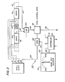
- a pixel control gate 45 which may, for example comprise a flip-flop, is provided in series with pixel output lead 46.
- An image size control 100 is provided, having a suitable Image Size Selector 101 for use by the operator or user in selecting the image size desired. Normally, Image Size Selector 101 would be incorporated into and made part of the control console or panel (not shown) of scanner 12.
- a binary rate multiplier (BRM) 102 which may comprise a Texas Instruments Model 7497 BRM, controls image size in the X-direction.
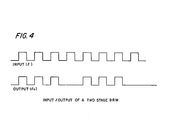
- BRM 102 incorporates a programmable multiplier enabling a selected output frequency that is a fraction of the input frequency, to be obtained, depending upon the binary multiplier value N applied.
- N the binary multiplier value
- BRM 102 drops selective clock cycles from the input clock frequeney.
- Clock pulses (20 ⁇ ) at a frequency 2 times the frequency f of the pixel clock pulses 0 ⁇ are input to BRM 102 through clock input lead 106 from pixel clock 42.
- Control lead 107 inputs the multiplier value N to BRM 102 in accordance with the image size selected by the user or operator.
- Changes in image size along the X-axis are effected by either speeding up or slowing down the frequency (f) of the clock rate (0) at which image pixels are clocked through pixel output lead 46.
- the former expands the size of the image while the latter reduces the image size, the degree of which is dependent upon the amount by which the frequency (f) of the pixel clock pulses is changed.
- BRM 102 functions to selectively reduce the frequency of the clock signals 20 input thereto in accordance with the multiplier value N input thereto by Image Size Selector 101. Where no change in image size is desired, a multiplier value of 32 is output by Image Size Selector 101 to BRM 102. Accordingly, the frequency of the control pulses output by BRM 102 to Pixel Control Gate 45 is one-half the frequency of the input clock signal 20 ⁇ to BRM 102. As a result, the frequency of the control pulses to gate 45 match that of pixel clock 0. Pixels are therefore output from Pixel Control Gate 45 at the same clock rate (0 ⁇ ) as the pixels are input and hence no change in image size along the X-axis occurs.
- the multiplier value N input to BRM 102 increases the frequency of the control pulses output by BRM 102 to control gate 45 to a frequency greater than the frequency of the pixel clock pulses 0 ⁇ .
- the rate at which image pixels are output from Pixel Control Gate 45 is increased, enlarging the image along the X-axis.
- maximum image magnification may be increased by increasing the frequency of the input clock signal from pixel clock 42 to BRM 102.
- the multiplier value N output by Image Size Selector 101 reduces the frequency of the control pulses output by BRM 102 to control gate 45 to a frequency less than the frequency of the pixel clock pulses 0 ⁇ . As a result, the rate at which image pixels are output from control gate 45 is reduced, reducing the image along the X-axis.
- Changes in image size along the Y-axis are effected by either speeding up or slowing down the scan speed of scanning carriage 32. Increasing the scan speed of carriage 32 reduces the image size while decreasing the carriage scan speed increases image size.
- control over scanning carriage 32 of scanner 12 is exercised by a suitable controller 72 which may, for example, comprise a micro-processor (MPU) in accordance with the magnification selected by the user or operator through Image Size Selector 101.
- a Shaft Encoder 73 is provided on the output shaft (drive screw 37) of scanning carriage drive motor 39. Encoder 73 serves to generate quadrature (i.e. 90a out of phase) signals in lead 74 in response to rotation of motor 39 in either a forward or reverse direction.
- a Direction Detector 75 determines from the phase relationship of the signals output by encoder 7 ' 3 the direction of rotation of motor 39 and hence the direction of movement of scanning carriage 32, and outputs either forward (FOR) or reverse (REV) control pulses to forward (SCAN) and reverse (RETURN) position counters 77, 78 respectively in response thereto.
- Forward (SCAN) and reverse (RETURN) position counters 77, 78 are preset to a maximum count representing the home position 80 of scanning carriage 32.
- counter 77 is decremented by signal pulses output by encoder 73.
- counter 78 is decremented.
- motor 39 may be initially energized in the reverse (REV) direction to drive scanning carriage 32 in the reverse (i.e. RETURN) direction until the carriage is brought into abutment with a carriage stop or bumper (not shown).
- Counters 77, 78 may then be zeroed and set to the predetermined maximum count.
- the instantaneous count on counters 77, 78 reflects the position of carriage 32 along the scan path.
- the carriage position may be determined at any point during scan by subtracting the count on forward counter 77 from the count on reverse counter 78.
- a Programmable Frequency Generator 82 provides a frequency signal (REF) which is input via lead 83 and Multiplexer 84 to Phase Detector 85 of phase lock loop control 86 for phase locked motor operation.
- Multiplexer 84 is controlled by direction signals (DIRECTION) from Controller 72, Multiplexer 84 during scan, coupling the forward (FOR) control pulses of Direction Detector 75, together with the forward reference signal (REF) to Phase Detector 85, and during carriage return, coupling the reverse (REV) control pulses of Direction Detector 75, together with the reverse reference signal (REF) to Phase Detector 85.
- Direction signals DIRECTION
- Phase Detector 85 compares the frequencies of forward (FOR) and reverse (REV) control pulses with the frequency of the reference signal (REF) input by frequency generator 82.
- the frequency of the reference signal (REF) output by generator 82 is set by control signals (SPEED) from Controller 72 in response to the signal in lead 108 from Image Size Selector 101.
- Control over scan carriage motor 39 is exercised through phase locked loop section 86, the output of Phase Detector 85 thereof being input to Adder 88 which sums the outputs of Phase Detector 85 in accordance with a predetermined formula.
- the signal output of Adder 88 is input via loop Filter 89 to Power Amplifier 90 controlling power input to motor 39.
- Filter 89 preferably comprises a low pass active filter with predetermined gain (i.e. 2.5), filter 89 being tuned to roll off at 100 cycles to filter out transients.
- a signal (DIRECTION FOR-REV) from Controller 72 sets Multiplexer 84 in accordance with the direction in which scan carriage 32 is to move, i.e., in the forward (SCAN) direction or reverse (RETURN) direction.
- Controller 50 loads progressively increasing frequency control signals, into Frequency Generator 82.
- Generator 82 responds by outputting to Phase Detector 85 reference signals (REF) at the frequencies selected.
- the first reference signal frequency is relatively low (i.e. 1 K.c.) with subsequent reference signals being increased stepwise in frequency.
- the frequency steps are reduced from relatively large (coarse) steps to relatively small (fine) steps.
- Phase Detector 85 compares the frequency of the reference signal (REF) from Frequency Generator 82 with the frequency of the signal representing the speed at which scan carriage 32 is moving as output by Shaft Encoder 73. Where a difference exists, an error signal is generated.
- the error signal is input through Filter 89 to Power Amplifier 90 to energize carriage drive motor 39.
- Motor 39 accelerates carriage 32 in the desired direction. The increase in the speed of carriage 32 in turn increases the frequency of the signal output by Shaft Encoder 73 until the frequency of the reference signal (REF) and the frequency of the signal from Shaft Encoder 73 match, at which point the error signal output by Phase Detector 85 falls to zero, interrupting power to motor 39.
- Controller 72 periodically resets Frequency Generator 82 to step up the frequency of the signal output by generator 82.
- Phase lock loop 86 responds to energize carriage drive motor 39 and accelerate carriage 32 until the carriage has been stepped through the speed plateaus represented by each successive reference signal to the final predetermined carriage speed.
- the final carriage speed in the scan direction is dependent upon the image size selected as represented by the signal input to controller 72 from Image Size Selector 10L
- the return speed of scan carriage 32 is preferably preset for an optimum scanning carriage return speed.
- phase lock loop 86 serves to maintain carriage 32 at .the desired operating speed. Should scan carriage 32 slow, Phase Detector 85 detects the change in frequency between the signal output of Shaft Encoder 73 and the reference signal output by generator 82 and generates an error signal energizing motor 39.
- a signal from Controller 72 closes switch 91 to short out Filter 89, thereby providing a gain of zero. With gain set to zero, power to carriage motor 39 is interrupted, stopping scan carriage 32.
- Phase Detector 85 may comprise a Motorola MC 4044 Phase Frequency Comparator which generates an output proportional to the phase or frequency difference between the encoder signal and the reference signal (REF) input by generator 82, while Shaft Encoder 73 may comprise a Model 992-500 OCLP manufactured by Disc Instruments.
- Counters 77, 78 may comprise Intel 8253 16 bit down counters while Adder 88 may comprise a 741 Differential Amplifier.
- Programmable Frequency Generator 82 preferably consists of a crystal clock and programmable counters.
Landscapes
- Engineering & Computer Science (AREA)
- Physics & Mathematics (AREA)
- General Physics & Mathematics (AREA)
- Multimedia (AREA)
- Signal Processing (AREA)
- Theoretical Computer Science (AREA)
- Facsimile Scanning Arrangements (AREA)
- Editing Of Facsimile Originals (AREA)
- Combination Of More Than One Step In Electrophotography (AREA)
- Control Of Velocity Or Acceleration (AREA)
Applications Claiming Priority (2)
| Application Number | Priority Date | Filing Date | Title |
|---|---|---|---|
| US06/128,018 US4366508A (en) | 1980-03-07 | 1980-03-07 | Image magnification and demagnification system |
| US128018 | 1993-09-28 |
Publications (4)
| Publication Number | Publication Date |
|---|---|
| EP0035875A2 true EP0035875A2 (fr) | 1981-09-16 |
| EP0035875A3 EP0035875A3 (en) | 1982-01-06 |
| EP0035875B1 EP0035875B1 (fr) | 1985-12-11 |
| EP0035875B2 EP0035875B2 (fr) | 1989-07-05 |
Family
ID=22433190
Family Applications (1)
| Application Number | Title | Priority Date | Filing Date |
|---|---|---|---|
| EP81300918A Expired EP0035875B2 (fr) | 1980-03-07 | 1981-03-05 | Appareil et procédé d'agrandissement ou de réduction d'éléments d'image |
Country Status (6)
| Country | Link |
|---|---|
| US (1) | US4366508A (fr) |
| EP (1) | EP0035875B2 (fr) |
| JP (1) | JPS56137771A (fr) |
| CA (1) | CA1202130A (fr) |
| DE (1) | DE3173169D1 (fr) |
| SU (1) | SU1281183A3 (fr) |
Cited By (5)
| Publication number | Priority date | Publication date | Assignee | Title |
|---|---|---|---|---|
| FR2540319A1 (fr) * | 1983-02-02 | 1984-08-03 | Thomson Csf | Analyseur d'images fixes |
| EP0183166A3 (en) * | 1984-11-26 | 1987-08-05 | Data Recording Systems, Inc. | Dual mode laser printer |
| FR2610158A1 (fr) * | 1987-01-27 | 1988-07-29 | Canon Kk | Appareil de traitement d'images |
| WO1996007268A1 (fr) * | 1994-08-31 | 1996-03-07 | Polaroid Corporation | Systeme de traitement d'image par effet zoom reel dans une imprimante electronique a analyse par points lumineux |
| US10676388B2 (en) | 2015-12-18 | 2020-06-09 | Heraeus Quarzglas Gmbh & Co. Kg | Glass fibers and pre-forms made of homogeneous quartz glass |
Families Citing this family (28)
| Publication number | Priority date | Publication date | Assignee | Title |
|---|---|---|---|---|
| JPS5772465A (en) * | 1980-10-23 | 1982-05-06 | Canon Inc | Digital signal converting device |
| US4423439A (en) * | 1981-03-03 | 1983-12-27 | Canon Kabushiki Kaisha | Facsimile transmitter |
| JPS5866932A (ja) * | 1981-10-16 | 1983-04-21 | Fuji Photo Film Co Ltd | 放射線画像再生装置 |
| JPS58119259A (ja) * | 1982-01-08 | 1983-07-15 | Fuji Xerox Co Ltd | フアクシミリ装置 |
| US4587621A (en) * | 1982-03-08 | 1986-05-06 | The Mead Corporation | Device for electrical variable magnification of document image |
| AU575786B2 (en) * | 1982-10-04 | 1988-08-11 | Canon Kabushiki Kaisha | Image forming system |
| JPS59164569A (ja) * | 1983-03-08 | 1984-09-17 | Canon Inc | カラ−画像処理装置 |
| JPS6055767A (ja) * | 1983-08-25 | 1985-04-01 | インタ−ナショナル ビジネス マシ−ンズ コ−ポレ−ション | イメージのビット数を減少する方法及び装置 |
| US4538185A (en) * | 1983-09-30 | 1985-08-27 | Xerox Corporation | Platen cover for document boundary detection in raster scanners |
| US4825250A (en) * | 1984-08-30 | 1989-04-25 | Canon Kabushiki Kaisha | Image forming apparatus including exposure scanning means |
| JPS61122623A (ja) * | 1984-11-19 | 1986-06-10 | Canon Inc | 投影装置 |
| JPH0681225B2 (ja) * | 1985-04-09 | 1994-10-12 | キヤノン株式会社 | 画像読み取り装置 |
| US5195148A (en) * | 1985-05-22 | 1993-03-16 | Minolta Camera Kabushiki Kaisha | Image reader having electrical and optical means for varying magnification |
| US5168369B1 (en) * | 1985-05-22 | 1997-07-29 | Minolta Camera Kk | Image reader having electrical and optical means for varying magnification |
| JPH06101780B2 (ja) * | 1985-05-22 | 1994-12-12 | ミノルタ株式会社 | 画像読取装置 |
| US4807156A (en) * | 1987-03-23 | 1989-02-21 | Xerox Corporation | Adjustable print size control for raster output scanners |
| US5151662A (en) * | 1991-06-24 | 1992-09-29 | Motorola, Inc. | Circuit and method of signal differentiation |
| US5293475A (en) * | 1991-11-18 | 1994-03-08 | Taylor Publishing Company | Electronic yearbook publication system |
| US5900002A (en) * | 1995-01-09 | 1999-05-04 | Josten, Inc. | Method and apparatus for manipulating page layouts in a desktop publishing system |
| US6031560A (en) * | 1996-04-18 | 2000-02-29 | Eastman Kodak Company | High resolution medical diagnostic laser printer |
| US6462842B1 (en) * | 1998-10-06 | 2002-10-08 | National Semiconductor Corporation | Apparatus, method, and computer program for increasing scanner data throughput |
| US7570394B2 (en) * | 2003-03-27 | 2009-08-04 | Xerox Corporation | System for determining the size of an original image, such as in a digital copier |
| US20060061832A1 (en) * | 2004-09-17 | 2006-03-23 | Christa Ferguson | Method to unlock scanner carriage without user intervention |
| US7101003B2 (en) * | 2005-01-27 | 2006-09-05 | Dell Products L.P. | Hybrid laser and inkjet printer |
| US7852510B2 (en) * | 2005-04-28 | 2010-12-14 | Xerox Corporation | Systems and methods for setting configuring rendering parameters for high-speed rendering devices |
| US7755654B2 (en) * | 2006-07-25 | 2010-07-13 | Hewlett-Packard Development Company, L.P. | Pixel |
| JP5198156B2 (ja) * | 2008-06-09 | 2013-05-15 | オリンパス株式会社 | 撮像装置 |
| JP5958224B2 (ja) * | 2012-09-19 | 2016-07-27 | 株式会社Jvcケンウッド | 表示装置及び表示方法 |
Family Cites Families (15)
| Publication number | Priority date | Publication date | Assignee | Title |
|---|---|---|---|---|
| GB1166091A (en) * | 1966-05-09 | 1969-10-01 | Crosfield Electronics Ltd | Improvements relating to Electro-Optical Scanners for Image Reproduction |
| DE1588313A1 (de) * | 1967-12-06 | 1970-12-10 | Hell Rudolf Dr Ing Fa | Verfahren zum Antrieb von Trommel-Klischiermaschinen |
| JPS513160A (fr) * | 1974-06-25 | 1976-01-12 | Matsushita Electric Industrial Co Ltd | |
| US4019153A (en) * | 1974-10-07 | 1977-04-19 | The Charles Stark Draper Laboratory, Inc. | Digital phase-locked loop filter |
| GB1549714A (en) * | 1975-05-12 | 1979-08-08 | Ecrm | Making halftone reproductions |
| US4054914A (en) * | 1975-10-29 | 1977-10-18 | Olympus Optical Company Limited | Facsimile scanning conversion system |
| US4017719A (en) * | 1975-12-18 | 1977-04-12 | Rca Corporation | Binary rate multiplier with means for spacing output signals |
| JPS6037464B2 (ja) * | 1976-07-20 | 1985-08-26 | 大日本スクリ−ン製造株式会社 | 倍率可変画像複製方法 |
| US4113378A (en) * | 1977-03-02 | 1978-09-12 | Itek Corporation | Linear exposure control system |
| US4169275A (en) * | 1977-03-10 | 1979-09-25 | Xerox Corporation | Reproduction scanning system having intermediate storage between input and output scanning stations |
| US4092632A (en) * | 1977-05-02 | 1978-05-30 | Xerox Corporation | Crossover arrangement for multiple scanning arrays |
| US4124871A (en) * | 1977-08-31 | 1978-11-07 | International Business Machines Corporation | Image data resolution change apparatus and process utilizing boundary compression coding of objects |
| JPS6030470B2 (ja) * | 1978-03-29 | 1985-07-16 | 富士通株式会社 | 信号密度変換方式 |
| GB2038142B (en) * | 1978-12-15 | 1982-11-24 | Ibm | Image data compression |
| US4275450A (en) * | 1979-08-01 | 1981-06-23 | Xerox Corporation | Magnification/demagnification apparatus and method |
-
1980
- 1980-03-07 US US06/128,018 patent/US4366508A/en not_active Expired - Lifetime
-
1981
- 1981-02-26 JP JP2758681A patent/JPS56137771A/ja active Pending
- 1981-02-27 CA CA000371959A patent/CA1202130A/fr not_active Expired
- 1981-03-05 DE DE8181300918T patent/DE3173169D1/de not_active Expired
- 1981-03-05 EP EP81300918A patent/EP0035875B2/fr not_active Expired
- 1981-03-06 SU SU813255797A patent/SU1281183A3/ru active
Cited By (6)
| Publication number | Priority date | Publication date | Assignee | Title |
|---|---|---|---|---|
| FR2540319A1 (fr) * | 1983-02-02 | 1984-08-03 | Thomson Csf | Analyseur d'images fixes |
| EP0183166A3 (en) * | 1984-11-26 | 1987-08-05 | Data Recording Systems, Inc. | Dual mode laser printer |
| FR2610158A1 (fr) * | 1987-01-27 | 1988-07-29 | Canon Kk | Appareil de traitement d'images |
| US5101282A (en) * | 1987-01-27 | 1992-03-31 | Canon Kabushiki Kaisha | Variable magnification image |
| WO1996007268A1 (fr) * | 1994-08-31 | 1996-03-07 | Polaroid Corporation | Systeme de traitement d'image par effet zoom reel dans une imprimante electronique a analyse par points lumineux |
| US10676388B2 (en) | 2015-12-18 | 2020-06-09 | Heraeus Quarzglas Gmbh & Co. Kg | Glass fibers and pre-forms made of homogeneous quartz glass |
Also Published As
| Publication number | Publication date |
|---|---|
| US4366508A (en) | 1982-12-28 |
| EP0035875B1 (fr) | 1985-12-11 |
| EP0035875B2 (fr) | 1989-07-05 |
| JPS56137771A (en) | 1981-10-27 |
| CA1202130A (fr) | 1986-03-18 |
| DE3173169D1 (en) | 1986-01-23 |
| SU1281183A3 (ru) | 1986-12-30 |
| EP0035875A3 (en) | 1982-01-06 |
Similar Documents
| Publication | Publication Date | Title |
|---|---|---|
| EP0035875B2 (fr) | Appareil et procédé d'agrandissement ou de réduction d'éléments d'image | |
| US4318135A (en) | Alignment system for scanning arrays | |
| US4506301A (en) | Multiple mode raster scanner | |
| US5043827A (en) | Combined asynchronous-synchronous document scanner | |
| CA1169913A (fr) | Controle de dimension d'image pour balayeurs de trame | |
| JPH0591258A (ja) | 画像読取装置 | |
| US4287536A (en) | Gain control for scanning arrays | |
| GB2070263A (en) | Automatic focusing | |
| EP0717325A2 (fr) | Appareil d'insertion d'images | |
| EP0578917B1 (fr) | Appareil de formation d'images à agrandissement variable | |
| JP3571499B2 (ja) | 原稿読み取り速度制御装置 | |
| EP0207711B1 (fr) | Système double pour l'exploration progressive par lignes à deux vitesses | |
| JP3280443B2 (ja) | 画像露光装置 | |
| EP0027371B1 (fr) | Lecteur à balayage de documents et procédé pour son fonctionnement | |
| JPS62161270A (ja) | デジタル複写機 | |
| JPH07336508A (ja) | 画像読み取り装置 | |
| GB2072357A (en) | Photocopying | |
| JPS6243667A (ja) | アナログ編集複写装置 | |
| JPS61247157A (ja) | 焦点調節装置 | |
| JPH03282443A (ja) | 露光制御装置 | |
| JP2002271584A (ja) | 画像読取装置 | |
| JPH05236218A (ja) | 画像読取装置 | |
| WO1986006181A1 (fr) | Balayage optique ameliore | |
| JPH04170851A (ja) | 画像読取装置 | |
| JPH02211465A (ja) | 複写機の変倍装置 |
Legal Events
| Date | Code | Title | Description |
|---|---|---|---|
| PUAI | Public reference made under article 153(3) epc to a published international application that has entered the european phase |
Free format text: ORIGINAL CODE: 0009012 |
|
| AK | Designated contracting states |
Designated state(s): BE DE FR GB NL |
|
| PUAL | Search report despatched |
Free format text: ORIGINAL CODE: 0009013 |
|
| 17P | Request for examination filed |
Effective date: 19811008 |
|
| AK | Designated contracting states |
Designated state(s): BE DE FR GB NL |
|
| GRAA | (expected) grant |
Free format text: ORIGINAL CODE: 0009210 |
|
| AK | Designated contracting states |
Designated state(s): BE DE FR GB NL |
|
| ET | Fr: translation filed | ||
| REF | Corresponds to: |
Ref document number: 3173169 Country of ref document: DE Date of ref document: 19860123 |
|
| PLBI | Opposition filed |
Free format text: ORIGINAL CODE: 0009260 |
|
| 26 | Opposition filed |
Opponent name: OCE-NEDERLAND B.V. Effective date: 19860510 |
|
| NLR1 | Nl: opposition has been filed with the epo |
Opponent name: OCE-NEDERLAND B.V. |
|
| PLBI | Opposition filed |
Free format text: ORIGINAL CODE: 0009260 |
|
| 26 | Opposition filed |
Opponent name: DR.-ING. RUDOLF HELL GMBH Effective date: 19860911 Opponent name: BSG TECHNISCHE BERATUNGS-GESELLSCHAFT MBH Effective date: 19860911 |
|
| NLR1 | Nl: opposition has been filed with the epo |
Opponent name: BSG TECHNISCHE BERATUNGS-GESELLSCHAFT MBH Opponent name: DR.-ING. RUDOLF HELL GMBH |
|
| PLAB | Opposition data, opponent's data or that of the opponent's representative modified |
Free format text: ORIGINAL CODE: 0009299OPPO |
|
| R26 | Opposition filed (corrected) |
Opponent name: OCE-NEDERLAND B.V. * 860911 DR.-ING. RUDOLF HELL G Effective date: 19860510 |
|
| PUAH | Patent maintained in amended form |
Free format text: ORIGINAL CODE: 0009272 |
|
| STAA | Information on the status of an ep patent application or granted ep patent |
Free format text: STATUS: PATENT MAINTAINED AS AMENDED |
|
| 27A | Patent maintained in amended form |
Effective date: 19890705 |
|
| AK | Designated contracting states |
Kind code of ref document: B2 Designated state(s): BE DE FR GB NL |
|
| ET3 | Fr: translation filed ** decision concerning opposition | ||
| NLR2 | Nl: decision of opposition | ||
| NLR3 | Nl: receipt of modified translations in the netherlands language after an opposition procedure | ||
| PGFP | Annual fee paid to national office [announced via postgrant information from national office to epo] |
Ref country code: DE Payment date: 19991231 Year of fee payment: 20 |
|
| PGFP | Annual fee paid to national office [announced via postgrant information from national office to epo] |
Ref country code: BE Payment date: 20000118 Year of fee payment: 20 |
|
| PGFP | Annual fee paid to national office [announced via postgrant information from national office to epo] |
Ref country code: GB Payment date: 20000301 Year of fee payment: 20 |
|
| PGFP | Annual fee paid to national office [announced via postgrant information from national office to epo] |
Ref country code: FR Payment date: 20000310 Year of fee payment: 20 |
|
| PGFP | Annual fee paid to national office [announced via postgrant information from national office to epo] |
Ref country code: NL Payment date: 20000331 Year of fee payment: 20 |
|
| BE20 | Be: patent expired |
Free format text: 20010305 *XEROX CORP. |
|
| PG25 | Lapsed in a contracting state [announced via postgrant information from national office to epo] |
Ref country code: GB Free format text: LAPSE BECAUSE OF EXPIRATION OF PROTECTION Effective date: 20010304 |
|
| PG25 | Lapsed in a contracting state [announced via postgrant information from national office to epo] |
Ref country code: NL Free format text: LAPSE BECAUSE OF EXPIRATION OF PROTECTION Effective date: 20010305 |
|
| REG | Reference to a national code |
Ref country code: GB Ref legal event code: PE20 Effective date: 20010304 |
|
| NLV7 | Nl: ceased due to reaching the maximum lifetime of a patent |
Effective date: 20010305 |