EP0035960A1 - Méthode et dispositif pour la distinction des véhicules de construction différente dans le trafic routier - Google Patents
Méthode et dispositif pour la distinction des véhicules de construction différente dans le trafic routier Download PDFInfo
- Publication number
- EP0035960A1 EP0035960A1 EP81730032A EP81730032A EP0035960A1 EP 0035960 A1 EP0035960 A1 EP 0035960A1 EP 81730032 A EP81730032 A EP 81730032A EP 81730032 A EP81730032 A EP 81730032A EP 0035960 A1 EP0035960 A1 EP 0035960A1
- Authority
- EP
- European Patent Office
- Prior art keywords
- loop
- detuning
- response value
- time
- predetermined response
- Prior art date
- Legal status (The legal status is an assumption and is not a legal conclusion. Google has not performed a legal analysis and makes no representation as to the accuracy of the status listed.)
- Granted
Links
- 238000000034 method Methods 0.000 title claims abstract description 23
- 238000010276 construction Methods 0.000 title description 4
- 230000004044 response Effects 0.000 claims abstract description 22
- 230000006698 induction Effects 0.000 claims abstract description 4
- 230000015654 memory Effects 0.000 claims description 25
- 239000003990 capacitor Substances 0.000 claims description 5
- 230000002123 temporal effect Effects 0.000 claims 1
- 238000005259 measurement Methods 0.000 description 12
- 238000011156 evaluation Methods 0.000 description 9
- 238000001514 detection method Methods 0.000 description 6
- 238000010586 diagram Methods 0.000 description 5
- 239000002184 metal Substances 0.000 description 5
- 230000015572 biosynthetic process Effects 0.000 description 3
- 230000004069 differentiation Effects 0.000 description 3
- 230000008859 change Effects 0.000 description 2
- 230000006870 function Effects 0.000 description 2
- 238000012544 monitoring process Methods 0.000 description 2
- 230000008569 process Effects 0.000 description 2
- 230000001133 acceleration Effects 0.000 description 1
- 230000033228 biological regulation Effects 0.000 description 1
- 230000037237 body shape Effects 0.000 description 1
- 230000003111 delayed effect Effects 0.000 description 1
- 238000011161 development Methods 0.000 description 1
- 230000018109 developmental process Effects 0.000 description 1
- 230000000694 effects Effects 0.000 description 1
- 238000007654 immersion Methods 0.000 description 1
- 238000009434 installation Methods 0.000 description 1
- 230000010354 integration Effects 0.000 description 1
- 238000012423 maintenance Methods 0.000 description 1
- 238000012545 processing Methods 0.000 description 1
- 230000009467 reduction Effects 0.000 description 1
- 238000012795 verification Methods 0.000 description 1
Images


Classifications
-
- G—PHYSICS
- G08—SIGNALLING
- G08G—TRAFFIC CONTROL SYSTEMS
- G08G1/00—Traffic control systems for road vehicles
- G08G1/01—Detecting movement of traffic to be counted or controlled
- G08G1/015—Detecting movement of traffic to be counted or controlled with provision for distinguishing between two or more types of vehicles, e.g. between motor-cars and cycles
Definitions
- the invention relates to a method for distinguishing vehicles of different types in road traffic by means of an induction loop embedded in the carriageway, and a device for carrying out the method.
- a vehicle crossing the loop field generates detuning signals in succession in both detectors, which form an electrical measure for the distribution of the metal masses of the vehicle influenced by the ground clearance.
- Each of the two detector circuits, each connected to a loop emits an output pulse corresponding to the dwell time of the vehicle above the loop, the two output pulses being staggered in time. The time offset depends on the distance with which the two loops are embedded in the lane one behind the other in the direction of travel.
- the loop detuning is fed to a subsequent logical evaluation as a measure of the ground clearance (DE-B-19 44 031) in order to distinguish between cars and small trucks, which have approximately the same length can.
- the disadvantage here is that two loops with the associated detector loops are required per lane. Because the cost of laying loops in the Lane is considerable because of the construction work involved, the arrangement of multiple loops per lane is quite expensive. Since the loop spacing at the installation locations can be different, additional means are required which enable adjustment when installing or replacing device parts in connection with maintenance work. In addition, an inadvertent incorrect adjustment can also lead to incorrect measurement results.
- the object of the invention specified in claim 1 is to specify, while avoiding the disadvantages mentioned, a method for distinguishing between types of vehicles which requires only one loop.
- the invention is based on the knowledge that the curves of the loop detuning have a different characteristic course depending on the type of vehicle, which can best be used to identify the type of vehicle by evaluating their symmetry properties - based on the first maximum of the amount of loop detuning. It is basically irrelevant for the evaluation whether the times between the start or end of the exceeding of a predetermined minimum loop detuning and the maximum value are mutually related or one of these times is related to the total time of exceeding a predefined loop detuning.
- the time period t x (running-in time) between reaching a first minimum detuning and the amount of the first detuning maximum forms the time period that elapses until a vehicle after the First triggering of the detector loop connected downstream of the loop reaches the point at which essential parts of the vehicle metal masses cover the loop area. Since the vast majority of vehicle types used in road traffic today have a uniform construction (conformity of the car body shapes in the front half, trucks with front-link construction), the distribution of the vehicle masses according to the aforementioned maximum makes an excellent differentiating criterion.
- the method according to the invention can also be used advantageously for measuring the speed of vehicles in road traffic, even independently of a device for distinguishing vehicles of different types.
- Use is made of the fact that the time from the first response of the loop detector to the first maximum of the detuning for different vehicles - but at least for vehicles of the same category, i.e. Vehicles that have the same magnitude of asymmetry in the detuning curve - is relatively constant in relation to the vehicle dimensions.
- This variable therefore represents a length reference variable, so that the time determined between the two values is inversely proportional to the driving speed of the vehicle and can serve as the basis for the speed measurement.
- the degree of loop detuning is used as an additional evaluation variable, in particular in the passenger car / small truck sector, as an additional variable for vehicle differentiation.
- memories can advantageously be used which, in the time t x, which elapses from the response until the first maximum is reached, are filled with a predetermined intensity (clock speed for counters, current for capacitors as storage elements, etc.) and are emptied after exceeding the maximum with an intensity that is in a predetermined target ratio to the storage intensity.
- a predetermined intensity clock speed for counters, current for capacitors as storage elements, etc.
- a decision is made as to whether a predetermined limit set for discrimination between two vehicle types is exceeded or undershot is.
- a corresponding circuit in which the reloading of memories in connection with vehicle length criteria is used for differentiation is known from DE-B-19 42 160, an entirely different quotient here in connection with the known two-loop method, namely that Ratio of the presence time of the vehicle over one of the loops to the difference in response times between two loops laid one behind the other in the direction of travel is evaluated.
- the formation of quotients in the method according to the invention can depend on the one used
- the type of circuit can also advantageously be determined mathematically or in other ways that enable the formation of a quotient in analog or digital circuits, for example by using logic circuits in which, depending on a counter reading, a memory location in a read-only memory is addressed, which stores the respective calculation result contains. In the case of such logic circuits, which contain the results in the manner of "tables", other memory areas whose memory contents correspond to the changed input conditions can advantageously be addressed by further measurement results by changing individual bits of the address.
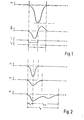
- FIG. 1 shows the loop detuning A L as a function of the time t when passing a motor vehicle. (Since the metal mass of a vehicle causes a reduction in inductance as it passes, the detuning is shown in the negative area of the diagram.) Directly below this is the differentiated curve dL / dt of the detuning curve, which is zero in the maximum of the detuning curve.
- a pulse shown below is formed from the negative region of the differentiated curve shape, the duration of which corresponds to the "run-in time" t x , ie the time which elapses from the response of the detector circuit connected downstream of the loop until the first maximum of the detuning is reached. Furthermore, a further pulse is shown in FIG. 1 below, which corresponds to the total duration (tp) of the time in which the detuning exceeds a predetermined threshold value.
- FIG. 3 in a block diagram, the signal processing is shown in a schematic form.
- a loop 1 laid in the carriageway is connected to a conventional detector circuit 2, which emits a signal a L proportional to the loop detuning.
- a change in the frequency or phase position of an AC voltage signal that is fed in as a result of the change in the inductance of loop 1 is evaluated.
- a signal is emitted by a first Schmitt trigger circuit 3 when the loop detuning exceeds a predetermined value (time tp in FIG. 1, below), while by a second Schmitt trigger circuit 5 connected downstream of a differential circuit 4 containing a capacitor C. a signal is emitted as long as the loop detuning increases after a vehicle enters the measuring range of the loop (time t x in FIG. 1).
- the incoming signals are linked to one another via logic circuits 6 and 7 in such a way that a switch 8 charges the individual memory elements formed by capacitors in operational amplifier circuits in a memory unit 9 with a predetermined intensity (current) during the "running-in time" via resistors R1 to R3.
- the resistors Rl to R3 are the same size in the illustrated embodiment. If the first maximum of the detuning is exceeded, the capacitors in the memory unit 9 are discharged via resistors Rl 'to R3' via a switch 10.
- the values of the resistors Rl to Rl ', R2 to R2' and R3 to R3 ' correspond to the ratios of those asymmetries t x to tp- x which form the limit values between the vehicle types to be output in each case. (If the limits from t x to tp, for example 0.55 and 0.3, are chosen between three types of vehicle to be evaluated, as in the example shown in FIG.
- the third memory unit with resistors R3 and R3 ' can be used to set a minimum or to define a maximum ratio of t x to tp of, for example, 0.1 or 0.7, which represents a limit for asymmetries in the detuning for which an evaluation is still being carried out.) In this way, incorrect measurements, for example during start-up or stopping processes in Traffic jams can be avoided.
- the storage unit 9 is put into an initial state by additional means (not shown) when the presence of a vehicle in the detection area of the loop has ended, ie the loop detuning is below the response value.
- the output signals of the memory unit 9 are fed to an impedance converter circuit 11, the outputs of which are connected to a digital memory 12, which records the states of the memories in the memory unit 9 when the loop detuning falls below the response level again. Any memory unloaded at this time means that by exceed the duration tp- x , the limit set between two vehicle categories was exceeded, i.e. it was not a car, but a truck or truck.
- the digital memory 12 is reset at the end of the evaluation time specified by the delay circuit 17.
- the absolute amount of the loop detuning is also compared with a differential voltage U ref , so that a measure of the ground clearance of the vehicles is obtained by means of a comparator circuit 13.
- the outputs of the comparator circuit 13 are connected to a further digital memory 14, which records the respective comparison results for a vehicle.
- the outputs of the memory units 12 and 14 are in turn connected to inputs of a further logic circuit 15, which outputs the respective vehicle type according to the predetermined differentiation criteria with regard to the symmetry of the loop detuning and the absolute value of the loop detuning achieved and feeds it to a display or storage unit 16.
- the evaluation is delayed by a delay circuit 17 only after a predetermined time after the vehicle has left the detection area of the loop in order to ensure an evaluation that is independent of the measurement.
- FIG. 4 shows a supplementary circuit for the arrangement shown in FIG. 3, which makes it possible to determine the speed of vehicles in road traffic with a single-loop arrangement.
- an assumed reference length x is divided by a measured presence time t, here the output signal of the switch 8 in FIG. 3 representing a measure of the time period t x , from the first detection of the vehicle by the loop detector to the immersion of its maximum metal mass in the detection area passes.
- the driving speed is determined in a simple embodiment on the condition that an average value for the " Entry length "x, which is traveled on average by the vehicles from the first response until the detector is detuned to the maximum.
- the evaluation in unit 17 with the aid of AND gates 18, 19 or 20 is based on a different length reference value for these, depending on which type of vehicle was determined by the device for distinguishing vehicle types and accordingly in storage unit 12 is captured.
- a delay unit 21 ensures that the determination of the speed v is only carried out when the type of vehicle has already been established.
- the total presence time tp of a vehicle in the detection area of the loop can also be used to determine the speed, taking into account an average vehicle length for the respective vehicle category, the curve profiles in the unit 17 having to be adapted accordingly .
- the output of switch 8 the output of Schmitt trigger 3 is to be connected to the input of delay circuit 21.
- a traffic density analyzer 22 which contains, for example, a retriggerable mono-flop and emits a signal at its output as soon as the time interval between successive vehicles is so small that the mono-flop can no longer return to the initial state it is in, if no signal indicating a vehicle appears at the output of the Schmitt trigger 3.
- the speed determined for a car which is also to be taken over for the vehicles following it at close spacing, which are not cars, is then transferred from the unit 17 to a memory 24 and recorded there.
- a switch 27 is set via an OR gate 25 and an AND gate 26, the second input of which is controlled by the traffic density analyzer 22, such that the output of the memory 24 corresponds to the output of the Output for the speed is connected, so for the following non-cars, the previously determined speed of the car is used.
- the time of the distance of successive vehicles from which the speed is assumed to be the same increases with increasing speed of the traffic flow in the illustrated embodiment .
- a connection to the traffic density analyzer 22 is shown schematically from the output v in the arrangement shown, which changes the time constant of the mono-flop contained therein in the specified sense.
- the limit interval times for the assumption of a traffic flow at constant speed are in turn a function of the speed of the traffic flow.
Landscapes
- Physics & Mathematics (AREA)
- General Physics & Mathematics (AREA)
- Traffic Control Systems (AREA)
Priority Applications (1)
| Application Number | Priority Date | Filing Date | Title |
|---|---|---|---|
| AT81730032T ATE9621T1 (de) | 1980-03-11 | 1981-03-11 | Verfahren und vorrichtung zur unterscheidung von fahrzeugen unterschiedlicher bauart im strassenverkehr. |
Applications Claiming Priority (2)
| Application Number | Priority Date | Filing Date | Title |
|---|---|---|---|
| DE3009679 | 1980-03-11 | ||
| DE19803009679 DE3009679A1 (de) | 1980-03-11 | 1980-03-11 | Verfahren zur unterscheidung von fahrzeugen unterschiedlicher bauart im strassenverkehr |
Publications (2)
| Publication Number | Publication Date |
|---|---|
| EP0035960A1 true EP0035960A1 (fr) | 1981-09-16 |
| EP0035960B1 EP0035960B1 (fr) | 1984-09-26 |
Family
ID=6097118
Family Applications (1)
| Application Number | Title | Priority Date | Filing Date |
|---|---|---|---|
| EP81730032A Expired EP0035960B1 (fr) | 1980-03-11 | 1981-03-11 | Méthode et dispositif pour la distinction des véhicules de construction différente dans le trafic routier |
Country Status (3)
| Country | Link |
|---|---|
| EP (1) | EP0035960B1 (fr) |
| AT (1) | ATE9621T1 (fr) |
| DE (2) | DE3009679A1 (fr) |
Cited By (8)
| Publication number | Priority date | Publication date | Assignee | Title |
|---|---|---|---|---|
| DE3209377A1 (de) * | 1982-03-15 | 1983-09-22 | Siemens AG, 1000 Berlin und 8000 München | Verfahren zur fahrzeugdetektion im strassenverkehr |
| EP0126958A3 (en) * | 1983-05-28 | 1986-10-15 | Robert Bosch Gmbh | Moving objects data registering detector and analyzing method |
| FR2617315A1 (fr) * | 1987-06-23 | 1988-12-30 | Sfim | Procede et dispositif de discrimination du type d'un vehicule automobile en circulation |
| EP0286057A3 (en) * | 1987-04-03 | 1990-08-08 | Omron Tateisi Electronics Co. | Proximity switch having an oscillation circuit |
| FR2693301A1 (fr) * | 1992-07-06 | 1994-01-07 | Est Centre Etudes Tech Equip | Dispositif pour détecter une ou plusieurs roues d'un engin mobile roulant. |
| US6337640B2 (en) | 1999-03-31 | 2002-01-08 | Diamond Consulting Services Limited | Inductive loop sensor for traffic detection, and traffic monitoring apparatus and method using such a loop sensor |
| US6483443B1 (en) | 1999-03-31 | 2002-11-19 | Diamon Consulting Services Limited | Loop sensing apparatus for traffic detection |
| DE19817008B4 (de) * | 1997-04-22 | 2004-09-30 | Nu-Metrics, Inc. | Verfahren und Anordnung zur Analyse von Verkehr sowie ein Sensor hierfür |
Citations (1)
| Publication number | Priority date | Publication date | Assignee | Title |
|---|---|---|---|---|
| DE2817672B1 (de) * | 1978-04-19 | 1979-04-26 | Elmeg | Verfahren und Vorrichtung zur Ermittlung der Anwesenheit von Fahrzeugen ueber einer in der Fahrbahn angeordneten Messvorrichtung |
Family Cites Families (1)
| Publication number | Priority date | Publication date | Assignee | Title |
|---|---|---|---|---|
| DE2039916A1 (de) * | 1968-09-06 | 1972-02-17 | Siemens Ag | Einrichtung zur Unterscheidung zwischen unterschiedlichen Fahrzeugkategorien im Strassenverkehr |
-
1980
- 1980-03-11 DE DE19803009679 patent/DE3009679A1/de not_active Withdrawn
-
1981
- 1981-03-11 EP EP81730032A patent/EP0035960B1/fr not_active Expired
- 1981-03-11 AT AT81730032T patent/ATE9621T1/de not_active IP Right Cessation
- 1981-03-11 DE DE8181730032T patent/DE3166250D1/de not_active Expired
Patent Citations (1)
| Publication number | Priority date | Publication date | Assignee | Title |
|---|---|---|---|---|
| DE2817672B1 (de) * | 1978-04-19 | 1979-04-26 | Elmeg | Verfahren und Vorrichtung zur Ermittlung der Anwesenheit von Fahrzeugen ueber einer in der Fahrbahn angeordneten Messvorrichtung |
Non-Patent Citations (1)
| Title |
|---|
| Siemens-Zeitschrift, Band 44, Nr. 2, Februar 1970, seiten 61-65 Erlangen, DE, P. LINGENFELSER et al.: "Schleifendetektoren zum Messen des Strassenverkehrs" * seite 63, linke spalte, letzter absatz; seite 64, rechte spalte, absatz 2 * * |
Cited By (10)
| Publication number | Priority date | Publication date | Assignee | Title |
|---|---|---|---|---|
| DE3209377A1 (de) * | 1982-03-15 | 1983-09-22 | Siemens AG, 1000 Berlin und 8000 München | Verfahren zur fahrzeugdetektion im strassenverkehr |
| EP0089030A3 (fr) * | 1982-03-15 | 1987-01-28 | Siemens Aktiengesellschaft | Méthode de détection de véhicule pour trafic routier |
| EP0126958A3 (en) * | 1983-05-28 | 1986-10-15 | Robert Bosch Gmbh | Moving objects data registering detector and analyzing method |
| EP0286057A3 (en) * | 1987-04-03 | 1990-08-08 | Omron Tateisi Electronics Co. | Proximity switch having an oscillation circuit |
| FR2617315A1 (fr) * | 1987-06-23 | 1988-12-30 | Sfim | Procede et dispositif de discrimination du type d'un vehicule automobile en circulation |
| FR2693301A1 (fr) * | 1992-07-06 | 1994-01-07 | Est Centre Etudes Tech Equip | Dispositif pour détecter une ou plusieurs roues d'un engin mobile roulant. |
| WO1994001847A1 (fr) * | 1992-07-06 | 1994-01-20 | Centre D'etudes Techniques De L'equipement De L'est | Dispositif et procede pour detecter une ou plusieurs roues d'un vehicule |
| DE19817008B4 (de) * | 1997-04-22 | 2004-09-30 | Nu-Metrics, Inc. | Verfahren und Anordnung zur Analyse von Verkehr sowie ein Sensor hierfür |
| US6337640B2 (en) | 1999-03-31 | 2002-01-08 | Diamond Consulting Services Limited | Inductive loop sensor for traffic detection, and traffic monitoring apparatus and method using such a loop sensor |
| US6483443B1 (en) | 1999-03-31 | 2002-11-19 | Diamon Consulting Services Limited | Loop sensing apparatus for traffic detection |
Also Published As
| Publication number | Publication date |
|---|---|
| DE3166250D1 (en) | 1984-10-31 |
| EP0035960B1 (fr) | 1984-09-26 |
| DE3009679A1 (de) | 1981-09-24 |
| ATE9621T1 (de) | 1984-10-15 |
Similar Documents
| Publication | Publication Date | Title |
|---|---|---|
| DE102012107445B4 (de) | 2Verfahren zur Klassifizierung von fahrenden Fahrzeugen | |
| DE3421253C2 (fr) | ||
| DE2350990C2 (fr) | ||
| EP1176569A2 (fr) | Procédé de surveillance de l'état du trafic sur un réseau routier comportant des modifications effectives du trafic | |
| DE3146711A1 (de) | "system zur auswertung und anzeige der fahrweise eines kraftfahrzeugs" | |
| DE102010039949A1 (de) | Verfahren zur Erkennung fehlender Fahreraktivität am Lenkrad eines Kraftfahrzeugs | |
| EP0035960B1 (fr) | Méthode et dispositif pour la distinction des véhicules de construction différente dans le trafic routier | |
| DE1574109C2 (de) | Gerät zur Ermittlung der relativen Dichte von Verkehrsströmen auf Straßen | |
| DE4227789B4 (de) | Verfahren zum Bestimmen der Achsabstände von Eisenbahnfahrzeugen | |
| DE3209377C2 (de) | Verfahren zur Geschwindigkeitsermittlung im Straßenverkehr | |
| DE3911830A1 (de) | Verfahren und schaltung zur auswertung von kontinuierlich auftretenden zeitmarken | |
| DE69214034T2 (de) | Fahrzeugdetektor mit automatischer Empfindlichkeitseinstellung | |
| EP1084414B1 (fr) | Procede et dispositif permettant de controler l'entrefer d'installation d'un detecteur actif | |
| DE4041149C1 (en) | Vehicle type classification within traffic flow - comparing vehicle silhouette with patterns stored in memory | |
| EP1262760B1 (fr) | Méthode de détermination de la viscosité d'in fluide de travail d'un moteur à combustion | |
| DE10205971A1 (de) | Verfahren und Vorrichtung für die Bestimmung von Offsetwerten durch ein Histogrammverfahren | |
| CH654670A5 (de) | Verfahren und vorrichtung zur auswertung von signalen einer doppler-radar-geschwindigkeitsmesseinrichtung. | |
| EP0004892A2 (fr) | Méthode et dispositif pour déterminer la présence de véhicules au-dessus d'un dispositif de mesure disposé dans la chaussée | |
| EP0126958A2 (fr) | Détecteur pour l'enregistrement des données d'un objet en mouvement | |
| DE2537657C2 (de) | Verfahren und Einrichtung zum Messen und Registrieren der Geschwindigkeit geradlinig bewegter Objekte | |
| DE2302423A1 (de) | Verfahren zum erfassen von verkehrssituationen und zugehoerige detektorschaltung | |
| DE102010007650A1 (de) | Verfahren, Auswerte- und Steuereinheit und Schaltungsanordnung zur Ermittlung eines aktuellen Radumfangs | |
| EP1056063A1 (fr) | Méthode et dispositif de détection des conditions du trafic d'un segment de route | |
| DE69715948T2 (de) | Verfahren und Vorrichtung zur Messung der Geschwindigkeit eines Fahrzeuges | |
| EP0288952B1 (fr) | Procédé et dispositif de mesure de la vitesse de véhicules |
Legal Events
| Date | Code | Title | Description |
|---|---|---|---|
| PUAI | Public reference made under article 153(3) epc to a published international application that has entered the european phase |
Free format text: ORIGINAL CODE: 0009012 |
|
| AK | Designated contracting states |
Designated state(s): AT BE CH DE FR GB IT LI NL SE |
|
| 17P | Request for examination filed |
Effective date: 19811013 |
|
| GRAA | (expected) grant |
Free format text: ORIGINAL CODE: 0009210 |
|
| AK | Designated contracting states |
Designated state(s): AT BE CH DE FR GB IT LI NL SE |
|
| PG25 | Lapsed in a contracting state [announced via postgrant information from national office to epo] |
Ref country code: SE Effective date: 19840926 Ref country code: NL Effective date: 19840926 Ref country code: IT Free format text: LAPSE BECAUSE OF FAILURE TO SUBMIT A TRANSLATION OF THE DESCRIPTION OR TO PAY THE FEE WITHIN THE PRESCRIBED TIME-LIMIT;WARNING: LAPSES OF ITALIAN PATENTS WITH EFFECTIVE DATE BEFORE 2007 MAY HAVE OCCURRED AT ANY TIME BEFORE 2007. THE CORRECT EFFECTIVE DATE MAY BE DIFFERENT FROM THE ONE RECORDED. Effective date: 19840926 Ref country code: FR Free format text: THE PATENT HAS BEEN ANNULLED BY A DECISION OF A NATIONAL AUTHORITY Effective date: 19840926 Ref country code: BE Effective date: 19840926 |
|
| REF | Corresponds to: |
Ref document number: 9621 Country of ref document: AT Date of ref document: 19841015 Kind code of ref document: T |
|
| REF | Corresponds to: |
Ref document number: 3166250 Country of ref document: DE Date of ref document: 19841031 |
|
| PGFP | Annual fee paid to national office [announced via postgrant information from national office to epo] |
Ref country code: AT Payment date: 19850308 Year of fee payment: 5 |
|
| NLV1 | Nl: lapsed or annulled due to failure to fulfill the requirements of art. 29p and 29m of the patents act | ||
| PLBE | No opposition filed within time limit |
Free format text: ORIGINAL CODE: 0009261 |
|
| STAA | Information on the status of an ep patent application or granted ep patent |
Free format text: STATUS: NO OPPOSITION FILED WITHIN TIME LIMIT |
|
| EN | Fr: translation not filed | ||
| 26N | No opposition filed | ||
| PG25 | Lapsed in a contracting state [announced via postgrant information from national office to epo] |
Ref country code: AT Effective date: 19860311 |
|
| PG25 | Lapsed in a contracting state [announced via postgrant information from national office to epo] |
Ref country code: LI Effective date: 19860331 Ref country code: CH Effective date: 19860331 |
|
| GBPC | Gb: european patent ceased through non-payment of renewal fee | ||
| REG | Reference to a national code |
Ref country code: CH Ref legal event code: PL |
|
| PG25 | Lapsed in a contracting state [announced via postgrant information from national office to epo] |
Ref country code: DE Effective date: 19871201 |
|
| PG25 | Lapsed in a contracting state [announced via postgrant information from national office to epo] |
Ref country code: GB Effective date: 19881118 |