EP0036311A1 - Entraînement mécanique d'un matériau en bande vers une enrouleuse - Google Patents
Entraînement mécanique d'un matériau en bande vers une enrouleuse Download PDFInfo
- Publication number
- EP0036311A1 EP0036311A1 EP81301062A EP81301062A EP0036311A1 EP 0036311 A1 EP0036311 A1 EP 0036311A1 EP 81301062 A EP81301062 A EP 81301062A EP 81301062 A EP81301062 A EP 81301062A EP 0036311 A1 EP0036311 A1 EP 0036311A1
- Authority
- EP
- European Patent Office
- Prior art keywords
- recoiler
- slitting
- web
- uncoiler
- slitter head
- Prior art date
- Legal status (The legal status is an assumption and is not a legal conclusion. Google has not performed a legal analysis and makes no representation as to the accuracy of the status listed.)
- Withdrawn
Links
Images
Classifications
-
- B—PERFORMING OPERATIONS; TRANSPORTING
- B65—CONVEYING; PACKING; STORING; HANDLING THIN OR FILAMENTARY MATERIAL
- B65H—HANDLING THIN OR FILAMENTARY MATERIAL, e.g. SHEETS, WEBS, CABLES
- B65H19/00—Changing the web roll
- B65H19/22—Changing the web roll in winding mechanisms or in connection with winding operations
- B65H19/28—Attaching the leading end of the web to the replacement web-roll core or spindle
-
- B—PERFORMING OPERATIONS; TRANSPORTING
- B21—MECHANICAL METAL-WORKING WITHOUT ESSENTIALLY REMOVING MATERIAL; PUNCHING METAL
- B21C—MANUFACTURE OF METAL SHEETS, WIRE, RODS, TUBES, PROFILES OR LIKE SEMI-MANUFACTURED PRODUCTS OTHERWISE THAN BY ROLLING; AUXILIARY OPERATIONS USED IN CONNECTION WITH METAL-WORKING WITHOUT ESSENTIALLY REMOVING MATERIAL
- B21C47/00—Winding-up, coiling or winding-off metal wire, metal band or other flexible metal material characterised by features relevant to metal processing only
- B21C47/006—Winding-up, coiling or winding-off metal wire, metal band or other flexible metal material characterised by features relevant to metal processing only winding-up or winding-off several parallel metal bands
-
- B—PERFORMING OPERATIONS; TRANSPORTING
- B65—CONVEYING; PACKING; STORING; HANDLING THIN OR FILAMENTARY MATERIAL
- B65H—HANDLING THIN OR FILAMENTARY MATERIAL, e.g. SHEETS, WEBS, CABLES
- B65H35/00—Delivering articles from cutting or line-perforating machines; Article or web delivery apparatus incorporating cutting or line-perforating devices, e.g. adhesive tape dispensers
- B65H35/02—Delivering articles from cutting or line-perforating machines; Article or web delivery apparatus incorporating cutting or line-perforating devices, e.g. adhesive tape dispensers from or with longitudinal slitters or perforators
-
- B—PERFORMING OPERATIONS; TRANSPORTING
- B65—CONVEYING; PACKING; STORING; HANDLING THIN OR FILAMENTARY MATERIAL
- B65H—HANDLING THIN OR FILAMENTARY MATERIAL, e.g. SHEETS, WEBS, CABLES
- B65H2301/00—Handling processes for sheets or webs
- B65H2301/40—Type of handling process
- B65H2301/41—Winding, unwinding
- B65H2301/414—Winding
- B65H2301/4148—Winding slitting
-
- B—PERFORMING OPERATIONS; TRANSPORTING
- B65—CONVEYING; PACKING; STORING; HANDLING THIN OR FILAMENTARY MATERIAL
- B65H—HANDLING THIN OR FILAMENTARY MATERIAL, e.g. SHEETS, WEBS, CABLES
- B65H2301/00—Handling processes for sheets or webs
- B65H2301/50—Auxiliary process performed during handling process
- B65H2301/51—Modifying a characteristic of handled material
- B65H2301/513—Modifying electric properties
- B65H2301/5133—Removing electrostatic charge
Definitions
- the present invention relates to slitting lines in which an elongate web of material, such as sheet metal in coil form, is unwound from an uncoiler, slit into multiple strips by rotary slitting knives and coiled on a recoiler.
- the invention pertains to a method of and apparatus for conveniently feeding-up the web material by transferring its leading end from the uncoiler, through the slitter head that contains the slitting knives to the recoiler mandrel for attachment thereto.
- the present invention provides a means for significantly reducing the labor and time required for the feed-up operation in a sheet metal slitting line by replacing much of the manual effort heretofore required by mechanical effort.
- the result is a feed-up operation that is less hazardous to the workman and more efficient in terms of the costs heretofore attributed to this operation.
- a method of feeding web material from a coil on an uncoiler to a recoiler through a slitter head containing rotary slitting knives comprising the steps of moving said slitter head to a position closely adjacent said uncoiler; unwinding said web material from said uncoiler to place the leading end thereof at the nip of said slitting knives; engaging said web leading end by said slitting knives; moving said slitter head to a position closely adjacent said recoiler; operating said knives to move the leading end of said web into engagement with said recoiler; and attaching said web leading end to said recoiler.
- the invention also provides a web slitting line containing an uncoiler for carrying a coil of web material, a recoiler spaced from said uncoiler, a slitter head positioned intermediate said uncoiler and said recoiler and containing at least one pair of rotary slitting knives for slitting said web into a plurality of strips, and means for moving said slitter head from a position closely adjacent said uncoiler to a position closely adjacent said recoiler.
- the invention further provides a slitter head comprising a frame; opposed pairs of rotary knives mounted on said frame for slitting web material passed therebetween; a pair of opposed pinch rolls on said frame forwardly adjacent said rotary knives adapted to drive said web material thereto; and a peeling blade pivotally attached to said frame having a free end adapted to strip the outermost wrap of web material from said uncoiler when said frame is moved to a position adjacent thereto.
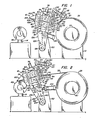
- a slitting line 10 consisting of an uncoiler 12, a recoiler 14 longitudinally spaced from the uncoiler and a slitter mechanism 16 interposed therebetween.
- the slitter mechanism includes a slitter head 18 containing pinch rolls 20 and pairs of opposed rotary slitting knives 22 and knock-down rolls 24 for slitting an elongate sheet metal web.
- the slitting knives 22 are typically notched as at 26 ( Figure 4) to slit the web in the manner described in detail in United States Patent No. 4,155,238, which manner of slitting will be more fully described hereinafter to an extent sufficient for an understanding of the present invention.
- a coil 28 of wound sheet metal is positioned on the mandrel 30 of uncoiler 12 and arranged to be conducted through the slitting head 18 where the web indicated as 32 in Figure 6 is continuously slit to produce parting lines 34 defining multiple strips 36 prior to winding on the recoiler 14.
- the uncoiler mandrel 30, as shown, is rotatably driven by a motor 38 through appropriate reduction gearing 40, all as is well known in the art.
- the recoiler 14, also of well-known construction comprises a horizontally disposed mandrel 42 that is driven by drive motor 44 through reduction gearing 46.
- the recoiler mandrel 42 is provided on its external surface with a gripper device 48 that includes an elongate slot 50 extending parallel to the mandrel axis and a gripper shaft 52 operated by a tool-receiving head 54.
- the shaft 52 contains a chordal flat that is caused, upon rotation of the shaft, to engage and hold the leading end 58 of web 32 fast to the mandrel 42.
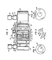
- the slitting head 18 comprises an open, generally rectangular frame structure having a bottom 58, a top 60 and opposed side members 62 and 64.
- the side members 62 and 64 each contain a vertically elongate opening 66 defining a guideway for slidable bearing blocks 68 that journal the opposite ends of drive shafts 70 and 72 that carry the slitting knives 22.
- the shafts 70 and 72 are operatively connected at one end to an appropriate drive 74 mounted on the adjacent side member.
- Fluid-operated cylinders 76 attached over the top of the respective side members 62 and 64 are operative through piston rods 78 for adjusting the spacing between the drive shafts 70 and 72 and thereby between the cutting edges of the opposed knives 22 in each pair.
- the frame side members 62 and 64 each attach oppositely spaced extension plates 80 and 82, the former pair extending rearwardly of the slitting head 18 and the latter extending forwardly thereof.
- Extension plates 80 each contain an elongate opening 84 for slidably mounting bearing blocks 86 that journal the ends of pinch rolls 20.
- the pinch rolls 20 may be selectively driven by appropriate gearing indicated generally at 90 from the slitter drive 74.
- Quick acting cylinders 92 are positioned atop the plates 80 and connect with the upper bearing blocks 86 to raise the upper pinch roll upon demand.
- a peeler 94 is pivotally mounted to the slitting head and extends transversely across the path traversed by the web 32 prior to its entering the slitting head 18.
- the peeler 94 in the described arrangement is formed by an elongate plate 96 having a knife edge 98 at its free end and gussets 99 at opposite sides, which gussets contain slightly oversized openings to permit the plate to be pivotally collared about the shaft of the lower pinch roll.
- a stop bar 100 extends between the extension plates 80 and serves to limit the extent of pivotal movement of the peeler downwardly to the position shown in Figure 2.
- Extension plates 82 which extend forwardly from each side member of the frame of slitting head 18 contain vertically spaced openings to receive bearings for journalling the shafts of the knock-down rolls 24.
- the knock-down rolls are driven by appropriate drive means, indicated generally as 101 in Figure 3, off the slitter drive 74.
- the drive means 101 includes an overrunning clutch (not shown) whereby the knock-down rolls 24 are permitted to rotate freely when movement of the web 32 is undertaken by the recoiler 14 as hereinafter more fully explained.
- the extension plates 82 also mount a web guide 102 comprising oppositely spaced formed plates 104 and 106 that serve to guide the leading end of web 32 into the gripper slot 50 on the recoiler mandrel 42.
- the plates 104 and 106 are arranged to conform generally to the external surface of the mandrel 42 and a bearing pad 108 is associated with lower plate 106 to permit the guide 102 to bear on the mandrel without gouging or otherwise damaging the surface thereof.
- a press roll 110 driven by motor 112 extends forwardly of the upper portion of the slitting head 18.
- the roll 110 and motor 112 are mounted from oppositely spaced arms 114 attached to the slitting head frame.
- the ends of the press roll 110 are journalled in bearing blocks 116 that are slidable in ways 118 and that are biased downwardly by springs 120. Stops 121 serve to retain the bearing blocks 116 in the ways 118.
- the slitting head 18 is supported for pivotal movement between the uncoiler 12 and recoiler 14 upon a pedestal 122 that contains pivot shaft 124.
- a pivot support 126 having arms 128 that straddle the pedestal 122 and an attachment key 130 extending between and uniting the arms serves to attach the slitting head.
- key 130 is adapted to be slidably received in a keyway 132 formed in the bottom 58 of the slitting head thereby facilitating removal by replacement of heads having various slitter configurations.
- Set screws (not shown) or other appropriate locking mechanism serve to attach the slitting head to the key.
- Pivotal movement is imparted to the assembly by a fluid operated cylinder 134 whose piston rod 136 is pin-connected to a clevis on the pivot support 126.
- the extent of pivotal movement of the slitter head support can be limited in the rearward direction by provision of a limit plate 138 that extends between the arms 128 and that bears on the forward face 140 of the pedestal 122.
- the hereindescribed apparatus is adapted to mechanically transfer the leading end of the web 32 of sheet metal being slit from the uncoiler 12 to the recoiler 14 for attachment to the recoiler mandrel 42 as part of the feed-up operation that is a necessary prerequisite to any continuous slitting operation.
- This function is accomplished as follows. With a coil 28 of sheet metal web material mounted on the mandrel 30 of uncoiler 12 fluid cylinder 134 is actuated to move the slitting head 18 rearwardly until stopped by abutment of the limit plate 138 with the forward face 140 of the pedestal 122, as shown in Figure 1.
- This action places the free edge of the peeler 94 in bearing engagement on the surface of the coil 28 just forwardly of the leading end of the outermost wrap and the press roll 110 in engagement with the coil just rearwardly thereof.
- the slitter mechanism drive 74 including the press roll motor 112 and the drive motor 38 of the uncoiler are actuated thereby causing the leading end of the web to unwrap from the coil and move across the upper surface of the peeler plate 96 toward the nip of the pinch rolls 88.
- cylinders 92 are actuated to momentarily raise the upper roll permitting the web to pass between the rolls.
- the web 32 is extended through the opening between the guide plates 104, 106 with an additional assist from the driving force of the knock-down rolls 24 until its leading end 58 extends sufficiently beyond the end of the opening between the plates 104, 106 to permit insertion of the web into the gripper mechanism 48 in the mandrel 42 of recoiler 14.
- the fluid cylinder 134 will be continuously operated to slowly pivot the slitter head assembly rearwardly as the coil on the recoiler mandrel is built up.
Landscapes
- Engineering & Computer Science (AREA)
- Mechanical Engineering (AREA)
- Replacement Of Web Rolls (AREA)
- Details Of Cutting Devices (AREA)
- Winding Of Webs (AREA)
Applications Claiming Priority (2)
| Application Number | Priority Date | Filing Date | Title |
|---|---|---|---|
| US06/129,967 US4285475A (en) | 1980-03-13 | 1980-03-13 | Mechanical feed-up of web material on a recoiler |
| US129967 | 1980-03-13 |
Publications (1)
| Publication Number | Publication Date |
|---|---|
| EP0036311A1 true EP0036311A1 (fr) | 1981-09-23 |
Family
ID=22442416
Family Applications (1)
| Application Number | Title | Priority Date | Filing Date |
|---|---|---|---|
| EP81301062A Withdrawn EP0036311A1 (fr) | 1980-03-13 | 1981-03-13 | Entraînement mécanique d'un matériau en bande vers une enrouleuse |
Country Status (7)
| Country | Link |
|---|---|
| US (1) | US4285475A (fr) |
| EP (1) | EP0036311A1 (fr) |
| JP (1) | JPS574848A (fr) |
| AU (1) | AU6830381A (fr) |
| BR (1) | BR8101407A (fr) |
| ES (1) | ES500285A0 (fr) |
| ZA (1) | ZA811243B (fr) |
Cited By (3)
| Publication number | Priority date | Publication date | Assignee | Title |
|---|---|---|---|---|
| EP0294554A1 (fr) * | 1987-06-06 | 1988-12-14 | JAGENBERG Aktiengesellschaft | Dispositif d'enroulage des bandes |
| EP0444008A1 (fr) * | 1990-02-21 | 1991-08-28 | BÖHLER YBBSTALWERKE Ges.m.b.H. | Ciseau du couteau circulaire rotatif pour l'écartement longitudinal de matière en nappe |
| EP0585092A1 (fr) * | 1992-08-26 | 1994-03-02 | Ykk Corporation | Enrouleuse automatique pour produits en forme de ruban |
Families Citing this family (6)
| Publication number | Priority date | Publication date | Assignee | Title |
|---|---|---|---|---|
| US4422587A (en) * | 1980-12-19 | 1983-12-27 | Gary Steel Products Corp. | Machine for slitting strips of sheet material |
| US4550881A (en) * | 1983-11-28 | 1985-11-05 | Deere & Company | Scrap scroller for a shear discharge conveying system |
| ES2062917B1 (es) * | 1992-10-01 | 1998-01-16 | Vazquez Bayarri Carmen | Maquina para la produccion de rollos de cinta sin mandril, y rollo de cinta obtenido por dicha maquina. |
| JPH09201934A (ja) * | 1995-11-21 | 1997-08-05 | Tohoku Ricoh Co Ltd | シートロールの自動先端剥離装置および製版装置 |
| JP6619241B2 (ja) * | 2016-01-19 | 2019-12-11 | コマツ産機株式会社 | コイル材通板装置、およびコイル材通板方法 |
| CN121553742B (zh) * | 2026-01-22 | 2026-04-03 | 健力粘扣带有限公司 | 一种粘扣带成型用装置及其使用方法 |
Citations (1)
| Publication number | Priority date | Publication date | Assignee | Title |
|---|---|---|---|---|
| FR2430804A1 (fr) * | 1978-07-10 | 1980-02-08 | Sundwiger Eisen Maschinen | Dispositif pour transporter les tetes de bandes metalliques divisees longitudinalement d'une cisaille a refendre a une bobineuse |
Family Cites Families (5)
| Publication number | Priority date | Publication date | Assignee | Title |
|---|---|---|---|---|
| US3461703A (en) * | 1964-10-30 | 1969-08-19 | Production Machinery Corp | Apparatus for uncoiling and processing metal strip |
| US4173313A (en) * | 1975-09-11 | 1979-11-06 | Rogers J W | Metal web handling method, apparatus and coil construct |
| US4170691A (en) * | 1975-09-11 | 1979-10-09 | Rogers J W | Steel metal web handling method, apparatus, and coil construct |
| US4171080A (en) * | 1977-07-25 | 1979-10-16 | Rogers J W | Steel metal web handling method |
| US4201352A (en) * | 1978-09-25 | 1980-05-06 | Loopco Industries, Inc. | Method and combination for winding strands of web material having varying thicknesses on a take-up drum |
-
1980
- 1980-03-13 US US06/129,967 patent/US4285475A/en not_active Expired - Lifetime
-
1981
- 1981-02-24 ZA ZA00811243A patent/ZA811243B/xx unknown
- 1981-03-11 BR BR8101407A patent/BR8101407A/pt unknown
- 1981-03-12 AU AU68303/81A patent/AU6830381A/en not_active Abandoned
- 1981-03-12 ES ES500285A patent/ES500285A0/es active Granted
- 1981-03-13 EP EP81301062A patent/EP0036311A1/fr not_active Withdrawn
- 1981-03-13 JP JP3549581A patent/JPS574848A/ja active Granted
Patent Citations (1)
| Publication number | Priority date | Publication date | Assignee | Title |
|---|---|---|---|---|
| FR2430804A1 (fr) * | 1978-07-10 | 1980-02-08 | Sundwiger Eisen Maschinen | Dispositif pour transporter les tetes de bandes metalliques divisees longitudinalement d'une cisaille a refendre a une bobineuse |
Cited By (5)
| Publication number | Priority date | Publication date | Assignee | Title |
|---|---|---|---|---|
| EP0294554A1 (fr) * | 1987-06-06 | 1988-12-14 | JAGENBERG Aktiengesellschaft | Dispositif d'enroulage des bandes |
| EP0444008A1 (fr) * | 1990-02-21 | 1991-08-28 | BÖHLER YBBSTALWERKE Ges.m.b.H. | Ciseau du couteau circulaire rotatif pour l'écartement longitudinal de matière en nappe |
| AT397481B (de) * | 1990-02-21 | 1994-04-25 | Boehler Ybbstalwerke | Kreismesserschere |
| EP0585092A1 (fr) * | 1992-08-26 | 1994-03-02 | Ykk Corporation | Enrouleuse automatique pour produits en forme de ruban |
| US5419511A (en) * | 1992-08-26 | 1995-05-30 | Yoshida Kogyo K.K. | Automatic winding machine for tape-like articles |
Also Published As
| Publication number | Publication date |
|---|---|
| JPS574848A (en) | 1982-01-11 |
| ES8205389A1 (es) | 1982-06-01 |
| US4285475A (en) | 1981-08-25 |
| ZA811243B (en) | 1982-03-31 |
| AU6830381A (en) | 1981-09-17 |
| ES500285A0 (es) | 1982-06-01 |
| JPS612570B2 (fr) | 1986-01-25 |
| BR8101407A (pt) | 1981-09-15 |
Similar Documents
| Publication | Publication Date | Title |
|---|---|---|
| DE2430514C3 (de) | Vorrichtung zum Verbinden einer von einer Ersatzwickelrolle abgezogenen Materialbahn mit einer von einer Vorratswickelrolle ablaufenden Materialbahn | |
| EP0442038B1 (fr) | Méthode et dispositif pour le remplacement automatique d'une bobine pleine par un nouveau noyau d'enroulement | |
| DE2455937C2 (de) | Vorrichtung zum Ablängen von Blech-Bandmaterial und Stapeln abgelängter Blechabschnitte | |
| DE3321213C2 (de) | Wickelmaschine zum Aufwickeln einer endlosen Bahn | |
| US4285475A (en) | Mechanical feed-up of web material on a recoiler | |
| DE2531072B2 (de) | Verfahren und Einrichtung zum Transport und zur Verarbeitung von Bogen in einer Stanztiegelpresse o.dgl | |
| EP0044923A2 (fr) | Unité de cisaillage pour ébouter un feuillard enroulé en couronne et/ou pour en prélever des échantillons | |
| CH645294A5 (de) | Buchblockschneidmaschine. | |
| EP0427126B1 (fr) | Dispositif pour changer une bande | |
| EP0507910B1 (fr) | Dispositif pour le sectionnement d'une bande de matiere | |
| DE2332780A1 (de) | Verfahren und vorrichtung zum fortlaufenden verbinden von papierrollen | |
| DE69900525T2 (de) | Vorrichtung und Verfahren zum Entfernen des Verpackungsmaterials von einer Materialbahnrolle | |
| EP1518615B1 (fr) | Dispositif pour l'alimentation du materiél en forme de bande et pour le rognage des bords de bande pour une machine d'usinage, en particulier pour des laminoirs de bande fine et pour des laminoirs de feuille | |
| EP0191809B1 (fr) | Dispositif d'enroulement d'articles en bandes | |
| DE102017109459B3 (de) | Schneideinrichtung zum Schneiden eines Endlosbands, insbesondere eines Stahl- oder Textilcordbands | |
| DE4134361A1 (de) | Wickelmaschine zum aufwickeln einer warenbahn, insbesondere einer papierbahn | |
| DE69113301T2 (de) | Vorrichtung zum kontinuierlichen Zuführen von Bahnen. | |
| DE2838563C2 (de) | Vorrichtung zum Erzielen festgewickelter Bunde gleichen Durchmessers beim Aufwickeln mehrerer Schmalbänder | |
| EP0406581A1 (fr) | Dispositif pour couper une bande sur un rouleau d'inversement | |
| EP3398740A1 (fr) | Dispositif de coupe permettant de couper une bande sans fin, en particulier une bande renforcée textile ou une bande en acier | |
| EP1444156B1 (fr) | Dispositif d'enroulement de bandes en continu | |
| CA1294537C (fr) | Organe de coupe pour fendre de minces bandes de materiau souple | |
| EP0019228A1 (fr) | Procédé et appareil pour la production de bobines rigides pour tapis, toisons, feutres et tricotages | |
| DE60009258T2 (de) | Blockerzeugungssystem und Verfahren zum Steuern des Faltens eines Blocks | |
| JPH085971Y2 (ja) | スリッタの巻取紙抑え装置 |
Legal Events
| Date | Code | Title | Description |
|---|---|---|---|
| PUAI | Public reference made under article 153(3) epc to a published international application that has entered the european phase |
Free format text: ORIGINAL CODE: 0009012 |
|
| AK | Designated contracting states |
Designated state(s): AT BE DE FR GB IT LU NL SE |
|
| 17P | Request for examination filed |
Effective date: 19811029 |
|
| STAA | Information on the status of an ep patent application or granted ep patent |
Free format text: STATUS: THE APPLICATION IS DEEMED TO BE WITHDRAWN |
|
| 18D | Application deemed to be withdrawn |
Effective date: 19830513 |