EP0036664B1 - Dispositif de raclage pour bassins de décantation, bassins de dépôt de boue ou analogues - Google Patents
Dispositif de raclage pour bassins de décantation, bassins de dépôt de boue ou analogues Download PDFInfo
- Publication number
- EP0036664B1 EP0036664B1 EP81102205A EP81102205A EP0036664B1 EP 0036664 B1 EP0036664 B1 EP 0036664B1 EP 81102205 A EP81102205 A EP 81102205A EP 81102205 A EP81102205 A EP 81102205A EP 0036664 B1 EP0036664 B1 EP 0036664B1
- Authority
- EP
- European Patent Office
- Prior art keywords
- clearing
- loading
- arm
- bridge
- blade
- Prior art date
- Legal status (The legal status is an assumption and is not a legal conclusion. Google has not performed a legal analysis and makes no representation as to the accuracy of the status listed.)
- Expired
Links
- 239000010802 sludge Substances 0.000 title claims description 14
- 239000007788 liquid Substances 0.000 claims 2
- 238000007790 scraping Methods 0.000 abstract 1
- 230000035508 accumulation Effects 0.000 description 9
- 238000009825 accumulation Methods 0.000 description 9
- 230000007423 decrease Effects 0.000 description 9
- 230000005484 gravity Effects 0.000 description 8
- 239000004576 sand Substances 0.000 description 2
- 238000007689 inspection Methods 0.000 description 1
- 238000012423 maintenance Methods 0.000 description 1
- 238000012986 modification Methods 0.000 description 1
- 230000004048 modification Effects 0.000 description 1
- 230000001681 protective effect Effects 0.000 description 1
- 238000004062 sedimentation Methods 0.000 description 1
Images
Classifications
-
- B—PERFORMING OPERATIONS; TRANSPORTING
- B01—PHYSICAL OR CHEMICAL PROCESSES OR APPARATUS IN GENERAL
- B01D—SEPARATION
- B01D21/00—Separation of suspended solid particles from liquids by sedimentation
- B01D21/02—Settling tanks with single outlets for the separated liquid
- B01D21/04—Settling tanks with single outlets for the separated liquid with moving scrapers
-
- B—PERFORMING OPERATIONS; TRANSPORTING
- B01—PHYSICAL OR CHEMICAL PROCESSES OR APPARATUS IN GENERAL
- B01D—SEPARATION
- B01D21/00—Separation of suspended solid particles from liquids by sedimentation
- B01D21/18—Construction of the scrapers or the driving mechanisms for settling tanks
Definitions
- the invention relates to a clearing device for sedimentation tanks, sludge traps or the like, with a movable bridge over the pool, a clearing blade mounted thereon by means of a swivel arm, and a loading device which generates a restoring force loading the clearing blade into the clearing position.
- a clearing device of this type is e.g. B. known from DE-C-1 179 160.
- the swivel arm of this scraper runs vertically. This is particularly advantageous in the case of longitudinal scrapers because the clearing blade can then actually be moved to the end of the pool, which is not possible with clearing blades dragged from the bridge at an angle. In this vertical position, however, the restoring moment generated by the dead weight of the clearing blade is practically zero, so that the clearing blade does not exert sufficient clearing force and would move backwards even with a small clearing resistance. For this reason, the loading device is provided, which ensures that a sufficiently large restoring and thus clearing force is exerted even in the vertical position of the clearing blade.
- the loading device consists of a load weight mounted on the bridge on a lever arm that is pivoted on the lever and that is connected to the swivel arm of the dozer blade via a toggle lever that is bent when the dozer blade is swiveled up and spread when the dozer blade is lowered.
- a disadvantage of the known device is that the restoring force exerted by the loading device decreases very strongly already at the beginning of the swiveling movement of the clearing blade. If the dozer blade z. B. is forced by a strong and solidified sludge accumulation to evade the vertical position against the maximum restoring force of the loading device, then the restoring force of the loading device decreases rapidly to such an extent that the clearing blade is unable to clear at least the upper layer of the sludge accumulation . This is despite the fact that the swivel arm and dozer blade produce a restoring force when they evade due to their own weight acting on a lever arm, but this does not compensate for the decrease in the restoring force of the loading device.
- the invention has for its object to provide a clearing device of compact design, which can also be used in confined spaces, and which is particularly suitable for the layer-by-layer clearing of pebble accumulations.
- a clearing device of the type mentioned at the outset is characterized in that the locking device generates a restoring force which initially increases when the clearing blade is swiveled up.
- the locking device is preferably designed in such a way that its restoring force increases and then decreases over an initial swiveling path of the clearing blade, which according to the invention is 20 to 45 °, preferably approx. 30 °.
- a scraper in which the loading device consists of a loading weight pivotally mounted on the bridge by means of a lever arm that this lever arm is rigidly connected to the swivel arm of the dozer blade and the loading weight is arranged lower than the swivel axis of the dozer blade when the dozer blade is in the clearing position.
- the lever arm relevant to the restoring moment exerted by the weight initially increases with respect to the swivel axis until the center of gravity of the load weight is at the same height as the swivel axis, and only then does it decrease again.
- the swivel arm of the clearing blade has in its upper region an angled course in the clearing direction of the bridge. This makes it possible to swivel the clearing blade up to a position above the pelvic crown without the swivel arm striking the bridge.
- the loading weight and the length of the lever arm connecting it to the swivel arm are preferably designed such that the loading weight is also within the outline of the bridge in the swung-up position.
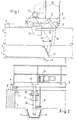
- a sand trap basin is indicated with a basin bottom 1, a side wall 2 with a basin crown 3, and a mud channel 4 which opens into a mud funnel 5.
- a bridge 8 can be moved on the pelvic crown 3 by means of running wheels 6 and lateral guide rollers 7.
- a pivot arm 10 is pivotally mounted, which carries the trapezoidal blade 11 at its lower end.
- the front edge of the clearing blade 11 is located almost exactly perpendicularly under the pivot axis 9.
- This clearing position is defined by a stop 12 provided on the bridge 8, against which the clearing arm 10 rests.
- the clearing blade 11 in the clearing position clears the sludge from the channel 4 into the sludge funnel 5 during the clearing movement of the bridge 8 from left to right in FIG. 1.
- the clearing blade 11 By actuating the motor of the cable winch, the clearing blade 11 can be pivoted up to a position which lies above the pelvic crown 3, so that the clearing blade is freely accessible for inspection and maintenance.
- the swivel arm 10, as can be seen from FIG. 1, has a shape that is cranked or angled in the forward direction of travel of the bridge 8.
- This angular shape makes it possible to swivel the clearing blade 1 up over the pelvic crown 3 without the upper part of the swivel arm 10 coming into contact with parts of the bridge 8, as would be the case if the swivel arm 10 were rectilinear.
- the z. B. is composed of several disks, so that the size of the weight can be changed by changing the number of disks.
- the length of the support arm 16 is dimensioned such that the distance of the center of gravity of the load weight 17 from the pivot axis 9 is sufficient to generate a torque of sufficient size which pushes the dozer blade 11 into its clearing position, so that the dozer blade 11 in the clearing position has the necessary Can apply clearing force.
- the center of gravity of the load weight 17 lies below the horizontal plane running through the pivot axis 9.
- the distance between the center of gravity of the load weight 17 and the vertical plane passing through the swivel axis 9 also increases, so that the torque loading the reamer 11 also increases.
- the lever arm of the center of gravity of the swivel arm and snow plow increases.
- the arrangement is preferably such that the center of gravity of the load weight 17 is at the same height as the pivot axis 9 when the pivot arm 10 has been pivoted with the clearing blade 11 from the clearing position by approximately 30 °.
- the clearing force therefore increases during the first 30 ° of the swiveling movement of the clearing blade 11 and only then decreases again.
- the clearing blade 11 is therefore able to clear at least the upper layer of this sludge accumulation with an increased clearing force corresponding to the pivoting of the loading weight 17 7, even in the case of sludge accumulations for the carrying through of which the loading force generated by the loading weight 17 in the clearing position is insufficient.
- the distance of the center of gravity of the load weight 17 from the vertical plane through the swivel axis 9 decreases again in spite of the initially still growing lever arm of the swivel arm center of gravity, so that the necessary for the further swiveling of the clearing blade accordingly to reduce the force to be applied by the winch.
- the arrangement of the load weight 17 and the length of its support arm 16 is so matched that the load weight in the (swung-dotted) position swung up is still completely within the outline of the bridge 8 and the railing 18 arranged on it located.
- Special protective grids or covers for the load weight 17 in the swung-up position are therefore not required, as would be the case if the load weight protruded beyond the bridge undercarriage or the railing.
- a support arm 16 does not necessarily have to be provided for fastening the load weight. Rather, the swivel arm 10 of the clearing blade itself can be bent or angled such that it has a part located at a sufficient distance behind the vertical plane defined by the swivel axis 9, to which the loading weight 17 can be attached directly. It is also possible to use an angled, one-piece arm, on which on the one hand the snow plow and on the other hand the load weight are fastened, and which is connected to the pivot axis 9 by a support arm projecting therefrom is.
- the invention can be used with the same advantages also for clearers, the swivel arm of which is dragged at a more or less large angle.
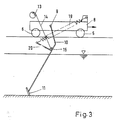
- FIG. 3 Another embodiment of the clearing device can be seen from FIG. 3, in which the swivel arm 10 is provided with a spring loading device instead of a load weight.
- an arm 20 is rigidly attached to the swivel arm 10, for example at point 15, at the end of which a tension spring 19 suspended on the bridge 8 is suspended. If the swivel arm 10 rotates clockwise about its swivel axis 9 in the drawing, the length of the tension spring 19 initially increases until its longitudinal axis intersects with the swivel axis 9, and then again.
- the back part characteristic is such that the load moment acting on the clearing blade 11 increases up to the maximum avoidance angle and then decreases again.
Landscapes
- Chemical & Material Sciences (AREA)
- Chemical Kinetics & Catalysis (AREA)
- Cleaning In General (AREA)
- Treatment Of Sludge (AREA)
- Load-Engaging Elements For Cranes (AREA)
- Chemical Treatment Of Metals (AREA)
- Jib Cranes (AREA)
Claims (7)
Priority Applications (1)
| Application Number | Priority Date | Filing Date | Title |
|---|---|---|---|
| AT81102205T ATE2419T1 (de) | 1980-03-26 | 1981-03-24 | Raeumvorrichtung fuer absetzbecken, schlammfaenge od. dgl. |
Applications Claiming Priority (2)
| Application Number | Priority Date | Filing Date | Title |
|---|---|---|---|
| DE3011752 | 1980-03-26 | ||
| DE19803011752 DE3011752A1 (de) | 1980-03-26 | 1980-03-26 | Raeumvorrichtung fuer absetzbecken, schlammfaenge o.dgl. |
Publications (2)
| Publication Number | Publication Date |
|---|---|
| EP0036664A1 EP0036664A1 (fr) | 1981-09-30 |
| EP0036664B1 true EP0036664B1 (fr) | 1983-02-09 |
Family
ID=6098435
Family Applications (1)
| Application Number | Title | Priority Date | Filing Date |
|---|---|---|---|
| EP81102205A Expired EP0036664B1 (fr) | 1980-03-26 | 1981-03-24 | Dispositif de raclage pour bassins de décantation, bassins de dépôt de boue ou analogues |
Country Status (5)
| Country | Link |
|---|---|
| US (1) | US4417983A (fr) |
| EP (1) | EP0036664B1 (fr) |
| AT (1) | ATE2419T1 (fr) |
| CA (1) | CA1167390A (fr) |
| DE (2) | DE3011752A1 (fr) |
Families Citing this family (8)
| Publication number | Priority date | Publication date | Assignee | Title |
|---|---|---|---|---|
| DE3314987A1 (de) * | 1983-04-26 | 1984-11-08 | Horst 6108 Weiterstadt Bormet | Waschgeraet fuer ablaufrinnen an klaerbecken |
| AT398751B (de) * | 1992-03-04 | 1995-01-25 | Sillipp Josef Ing | Waschgerät für kläranlagenablaufrinnen |
| US5250199A (en) * | 1992-06-15 | 1993-10-05 | Enviroland, Inc. | Sludge scraper apparatus |
| US5286384A (en) * | 1993-01-14 | 1994-02-15 | Enviroland, Inc. | Sludge scraper apparatus |
| US5454942A (en) * | 1994-08-23 | 1995-10-03 | Anglian Water Plc | Apparatus for the removal of floating sludge in dissolved air floatation basins at water purification and waste water treatment plants |
| KR100775467B1 (ko) * | 2001-09-27 | 2007-11-12 | 주식회사 포스코 | 석탄 수거차의 방향 전환장치 |
| MX2012007023A (es) * | 2009-12-17 | 2012-11-06 | Yoshino Gypsum Co | Dispositivo y metodo para limpiar una superficie de transporte. |
| JP7029814B2 (ja) * | 2019-08-06 | 2022-03-04 | 有限会社智寛 | 油水分離装置 |
Family Cites Families (3)
| Publication number | Priority date | Publication date | Assignee | Title |
|---|---|---|---|---|
| NL30744C (fr) * | 1929-08-23 | |||
| DE1584973C3 (de) * | 1965-12-23 | 1974-07-04 | Passavant - Werke Michelbacher Huette, 6209 Aarbergen | Schlammräumer für Klärbecken mit gewichtsbelastetem Räumschild |
| IT993760B (it) * | 1972-09-06 | 1975-09-30 | Prometall Uznach Ag | Dispositivo d estrazione per impianti di chiarificazione e di fognatura |
-
1980
- 1980-03-26 DE DE19803011752 patent/DE3011752A1/de not_active Withdrawn
-
1981
- 1981-03-20 US US06/245,731 patent/US4417983A/en not_active Expired - Fee Related
- 1981-03-24 EP EP81102205A patent/EP0036664B1/fr not_active Expired
- 1981-03-24 AT AT81102205T patent/ATE2419T1/de not_active IP Right Cessation
- 1981-03-24 DE DE8181102205T patent/DE3160056D1/de not_active Expired
- 1981-03-25 CA CA000373876A patent/CA1167390A/fr not_active Expired
Also Published As
| Publication number | Publication date |
|---|---|
| DE3011752A1 (de) | 1981-11-19 |
| ATE2419T1 (de) | 1983-03-15 |
| DE3160056D1 (en) | 1983-03-17 |
| EP0036664A1 (fr) | 1981-09-30 |
| US4417983A (en) | 1983-11-29 |
| CA1167390A (fr) | 1984-05-15 |
Similar Documents
| Publication | Publication Date | Title |
|---|---|---|
| DE1929177C3 (de) | Straßenräumgerät | |
| EP0271645A1 (fr) | Chasse-neige | |
| DE1759053A1 (de) | Reinigungsvorrichtung fuer Faenge wie Siebe,Fangrechen,Abscheidegitter usw. | |
| DE2046900C3 (de) | Mit einem Schiff gelenkig verbundene Laderampe | |
| EP0036664B1 (fr) | Dispositif de raclage pour bassins de décantation, bassins de dépôt de boue ou analogues | |
| CH651607A5 (en) | Trailer for snow vehicles, in particular for piste care | |
| EP0140139B1 (fr) | Soc pour un chasse-neige | |
| DE1658104C3 (de) | Räumvorrichtung für Absetzbecken | |
| DE2437723C2 (de) | Straßenpflug, insbesondere zum Schneeabtragen | |
| DE2135987A1 (de) | Mehrfach-Schneeaufbereitungsvorrichtung für Schihänge | |
| DE2257351C3 (de) | Abstreichvorrichtung für am Boden eines Beckens einer Klär- oder Eindickungsanlage befindliche Ablagerungen | |
| CH633450A5 (de) | Einrichtung zum praeparieren von schneepisten. | |
| DE3237944C2 (fr) | ||
| DE1584973A1 (de) | Schlammraeumer | |
| DE1482014B1 (de) | Maehvorrichtung,insbesondere zum Reinigen von Wassergraeben | |
| DE2203865B2 (de) | Schlammräumer für Klärbecken mit gewichtsbelastetem Räumschild | |
| DE29516479U1 (de) | Räum-Kehrvorrichtung für Lastkraftfahrzeuge | |
| DE1913382C3 (de) | Gerät zum Einebnen von Schneeflächen, insbesondere Skipisten | |
| DE3632718C2 (fr) | ||
| DE8812518U1 (de) | Antriebsvorichtung für den Räumer eines Klärbeckens | |
| DE2760021C2 (de) | An einem Trägerfahrzeug angeordnete Vorrichtung zum Lösen von auf einer Straßenoberfläche festhaftenden Verschmutzungen | |
| DE1814965C3 (de) | Schlammräumvorrichtung für rechteckige Absetzbecken | |
| DE3301316C2 (de) | Vorrichtung zum Positionieren eines an einem Saugrohr befestigten Schleppkopfes | |
| DE913908C (de) | Vorrichtung zur Saeuberung von Bahngleisen, insbesondere in Kohlengruben | |
| DE741690C (de) | Bodenbearbeitungsgeraet, insbesondere zur Herstellung von Rollfeldern fuer Flugplaetze |
Legal Events
| Date | Code | Title | Description |
|---|---|---|---|
| PUAI | Public reference made under article 153(3) epc to a published international application that has entered the european phase |
Free format text: ORIGINAL CODE: 0009012 |
|
| AK | Designated contracting states |
Designated state(s): AT BE CH DE FR IT LU NL |
|
| 17P | Request for examination filed |
Effective date: 19811014 |
|
| ITF | It: translation for a ep patent filed | ||
| GRAA | (expected) grant |
Free format text: ORIGINAL CODE: 0009210 |
|
| AK | Designated contracting states |
Designated state(s): AT BE CH DE FR IT LI LU NL |
|
| REF | Corresponds to: |
Ref document number: 2419 Country of ref document: AT Date of ref document: 19830315 Kind code of ref document: T |
|
| REF | Corresponds to: |
Ref document number: 3160056 Country of ref document: DE Date of ref document: 19830317 |
|
| PG25 | Lapsed in a contracting state [announced via postgrant information from national office to epo] |
Ref country code: LU Free format text: LAPSE BECAUSE OF NON-PAYMENT OF DUE FEES Effective date: 19830331 |
|
| ET | Fr: translation filed | ||
| PGFP | Annual fee paid to national office [announced via postgrant information from national office to epo] |
Ref country code: FR Payment date: 19840327 Year of fee payment: 4 |
|
| PGFP | Annual fee paid to national office [announced via postgrant information from national office to epo] |
Ref country code: CH Payment date: 19840427 Year of fee payment: 4 |
|
| PGFP | Annual fee paid to national office [announced via postgrant information from national office to epo] |
Ref country code: LU Payment date: 19860313 Year of fee payment: 4 |
|
| PG25 | Lapsed in a contracting state [announced via postgrant information from national office to epo] |
Ref country code: LI Effective date: 19860331 Ref country code: CH Effective date: 19860331 |
|
| PG25 | Lapsed in a contracting state [announced via postgrant information from national office to epo] |
Ref country code: FR Free format text: LAPSE BECAUSE OF NON-PAYMENT OF DUE FEES Effective date: 19861128 |
|
| REG | Reference to a national code |
Ref country code: CH Ref legal event code: PL |
|
| REG | Reference to a national code |
Ref country code: FR Ref legal event code: ST |
|
| ITTA | It: last paid annual fee | ||
| PGFP | Annual fee paid to national office [announced via postgrant information from national office to epo] |
Ref country code: NL Payment date: 19900331 Year of fee payment: 10 |
|
| PGFP | Annual fee paid to national office [announced via postgrant information from national office to epo] |
Ref country code: BE Payment date: 19900402 Year of fee payment: 10 |
|
| PG25 | Lapsed in a contracting state [announced via postgrant information from national office to epo] |
Ref country code: BE Effective date: 19910331 |
|
| BERE | Be: lapsed |
Owner name: PASSAVANT-WERKE A.G. & CO. K.G. Effective date: 19910331 |
|
| PG25 | Lapsed in a contracting state [announced via postgrant information from national office to epo] |
Ref country code: NL Effective date: 19911001 |
|
| NLV4 | Nl: lapsed or anulled due to non-payment of the annual fee | ||
| EPTA | Lu: last paid annual fee | ||
| PGFP | Annual fee paid to national office [announced via postgrant information from national office to epo] |
Ref country code: DE Payment date: 19960521 Year of fee payment: 16 |
|
| PGFP | Annual fee paid to national office [announced via postgrant information from national office to epo] |
Ref country code: AT Payment date: 19960522 Year of fee payment: 16 |
|
| PG25 | Lapsed in a contracting state [announced via postgrant information from national office to epo] |
Ref country code: AT Effective date: 19970324 |
|
| PG25 | Lapsed in a contracting state [announced via postgrant information from national office to epo] |
Ref country code: DE Effective date: 19971202 |
|
| PLBE | No opposition filed within time limit |
Free format text: ORIGINAL CODE: 0009261 |
|
| STAA | Information on the status of an ep patent application or granted ep patent |
Free format text: STATUS: NO OPPOSITION FILED WITHIN TIME LIMIT |