EP0036824A2 - Sitze mit neigungsverstellbarer Rückenlehne - Google Patents
Sitze mit neigungsverstellbarer Rückenlehne Download PDFInfo
- Publication number
- EP0036824A2 EP0036824A2 EP81400461A EP81400461A EP0036824A2 EP 0036824 A2 EP0036824 A2 EP 0036824A2 EP 81400461 A EP81400461 A EP 81400461A EP 81400461 A EP81400461 A EP 81400461A EP 0036824 A2 EP0036824 A2 EP 0036824A2
- Authority
- EP
- European Patent Office
- Prior art keywords
- seat
- profiles
- backrest
- profile
- curved
- Prior art date
- Legal status (The legal status is an assumption and is not a legal conclusion. Google has not performed a legal analysis and makes no representation as to the accuracy of the status listed.)
- Granted
Links
- 239000002184 metal Substances 0.000 claims abstract description 11
- 239000000463 material Substances 0.000 claims description 3
- 238000010276 construction Methods 0.000 description 5
- 230000004048 modification Effects 0.000 description 2
- 238000012986 modification Methods 0.000 description 2
- 241001080024 Telles Species 0.000 description 1
- 230000000295 complement effect Effects 0.000 description 1
- 239000000470 constituent Substances 0.000 description 1
- 238000012217 deletion Methods 0.000 description 1
- 230000037430 deletion Effects 0.000 description 1
- 230000005484 gravity Effects 0.000 description 1
- 238000004519 manufacturing process Methods 0.000 description 1
- 230000003014 reinforcing effect Effects 0.000 description 1
- 238000004904 shortening Methods 0.000 description 1
- 125000006850 spacer group Chemical group 0.000 description 1
Images


Classifications
-
- A—HUMAN NECESSITIES
- A47—FURNITURE; DOMESTIC ARTICLES OR APPLIANCES; COFFEE MILLS; SPICE MILLS; SUCTION CLEANERS IN GENERAL
- A47C—CHAIRS; SOFAS; BEDS
- A47C1/00—Chairs adapted for special purposes
- A47C1/02—Reclining or easy chairs
- A47C1/022—Reclining or easy chairs having independently-adjustable supporting parts
- A47C1/024—Reclining or easy chairs having independently-adjustable supporting parts the parts, being the back-rest, or the back-rest and seat unit, having adjustable and lockable inclination
- A47C1/025—Reclining or easy chairs having independently-adjustable supporting parts the parts, being the back-rest, or the back-rest and seat unit, having adjustable and lockable inclination by means of a rack-and-pinion or like gearing mechanism
-
- B—PERFORMING OPERATIONS; TRANSPORTING
- B60—VEHICLES IN GENERAL
- B60N—SEATS SPECIALLY ADAPTED FOR VEHICLES; VEHICLE PASSENGER ACCOMMODATION NOT OTHERWISE PROVIDED FOR
- B60N2/00—Seats specially adapted for vehicles; Arrangement or mounting of seats in vehicles
- B60N2/02—Seats specially adapted for vehicles; Arrangement or mounting of seats in vehicles the seat or part thereof being movable, e.g. adjustable
- B60N2/22—Seats specially adapted for vehicles; Arrangement or mounting of seats in vehicles the seat or part thereof being movable, e.g. adjustable the back-rest being adjustable
- B60N2/224—Stepwise movement mechanisms, e.g. ratchets
Definitions
- the invention relates to seats with adjustable back rests, in particular for vehicles.
- the backs of these seats are pivotally mounted around a transverse axis disposed in the lower rear area of the seat and means are provided for locking the backrest in a number of distinct angular positions around this axis.
- the slide elements in question were then essentially constituted by concentric grooves and ribs respectively forming hollows and protrusions on said wings and legs.
- the object of the present invention is to apply the above construction principle to seats, the seat and back frames of which are in the general form of frames made up of metal frame elements.
- the back frame of which comprises two curved metal profiles disposed respectively on the two sides of the back, each extending downward and forward the base of one sides of this backrest and centered on the same horizontal transverse axis situated in the vicinity of the pivot axis of the hips of the person seated on the seat, these profiles being able to interact with seat guiding members and means being provided for adjusting the relative positions of the profiles with respect to the guide members and for locking them in a plurality of separate mutual positions.
- the profiles are constituted by curved tubes and the guide members are constituted, for each tube, by two pairs of rollers.
- the guide members are constituted by two curved metal sections forming part of the seat frame, centered on the transverse axis above and capable of cooperating by sliding interlocking with the two sections of the backrest.
- the invention includes, apart from these main provisions, certain other provisions which are preferably used at the same time and which will be more explicitly discussed below.
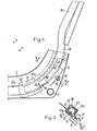
- Figure 1 of these drawings is a perspective view of a vehicle seat according to the invention, the two seat and back frames are here separated one from the other.
- FIGS. 2 and 3 show the same seat with its two frameworks mounted one on the other respectively in lateral view, portions cut according to II-II FIG. 3, and in cross section according to III-III FIG. 2.
- FIGS. 4 and 5 show a variant of a seat according to the invention, with its two frameworks still mounted one on the other, respectively in lateral view, portions cut according to IV-IV in FIG. 5, and in cross section according to VV in FIG. 4.
- Said axis X is here arranged in the vicinity of the pivot axis H of the hips of the seat user (see FIG. 2).
- this X axis is located at a height of the order of 12 to 15 cm above the lowest point of the middle zone of the carrying surface of the seat cushion and at a horizontal distance of the order of 15 to 20 cm er p before the base of the middle area of the back cushion carrying surface.
- One of the two curved sections of each pair is provided so as to wrap the other over more than half of its periphery so that after the beginning of their mutual interlocking, these sections can no longer undergo the one relative to the other, only relative sliding "circular", that is to say for which each moving point moves in an arc centered on the axis X.
- the mutually nested portion of the curved profiles corresponds to a relatively large arc of an axis X, this arc generally being between 45 and 90 ° and preferably of the order of 60 °.
- one of the profiles 6, linked to the back frame is a gutter having a relatively closed C profile.
- the other profile the profile of which has the general shape of a T, consists of a flat projection extending along a portion of disc and projecting from one of the flanges 1, this projection being produced by stamping said flange and being itself extended radially, both in the direction of the X axis and in the opposite direction, by lugs 8 - ( Figure 3) punctured in the areas of connection of said projection to the rest of the flange.
- the two series of coplanar legs 8 thus formed are themselves permanently capped by rods 9, 10 made of a plastic or other material having a low coefficient of friction and a good wear resistance.
- the gutter 6 is advantageously constituted by two curved pieces 6 1 , 6 centered on the axis X, welded one on the other at points 10 and each having a cross section in J.
- One of these parts 6 1 in the form of a relatively narrow rod, has an upper rectilinear extension 11 oriented upwards and backwards and forming with said part a sort of stretched sickle.
- This extension 11 is bevelled at 12 and welded to the arch 4 in an upper zone of the latter.
- the other part 6 2 wider than the part 6 1 , is in the general form of a vertical cheek with folded rear edge and its upper portion is welded not only on the part 6 1 and on the bottom of its extension upper 11, but also on the bottom of one leg of the arch 4.
- the rigid triangulated assembly thus formed has great resistance to deformation.
- the mounting of the back frame on the seat frame is carried out by first making the axes of the profiles 6 and 7-10 coincide, then by fitting in the end "circularly" the lower ends of the gutters 6 of the backrest the upper ends of the profiles 7-10 in T of the seat so that each gutter 6 joins the two furs 9 and 10 together covering a projection 7 while being able to slide along these.
- the backrest frame thus fitted onto the seat frame comes by gravity to occupy its lower position of maximum interlocking, position corresponding to the maximum inclination of the backrest on the vertical and in mutual contact with the end of travel ranges provided respectively on the profiles and / or on the frames.
- the number of circular racks 13 is equal to two and these racks consist of cut metal plates welded to the vertical cheeks of the pieces 6 2 so that their teeth are oriented downwards and backwards, while the toothed members 14, also two in number, are integral with 'A single transverse rigid bar 16 carried by the seat frame, at the rear thereof, and terminated at its two ends by the wheels 15.
- the toothed members 14 can have any desirable shape: this is how they can be constituted by pinions associated with angular locking means.
- these toothed members 14 each consist of two identical cylindrical pins of axes parallel to the axis X and symmetrical to each other with respect to the axis of the bar 16, pins capable of interacting with the teeth of the racks 13.
- the bar 16 is mounted so as to be able to roll and slide jointingly in two slots 17 hollowed out respectively in the two flanges 1 and elongated radially with respect to the axis X, and springs (not shown) are provided to constantly stress the bar 16 towards the front and upwards so as to introduce the pins 14 at the bottom of the notches opposite the racks correspond d ntes.
- This mechanism has the advantage of automatically ensuring excellent locking for each of its adjustment positions.
- the curved profile forming part of the back frame is constituted by a tubular element 18 which can either have an upper rectilinear extension 19 extending upwards and towards the rear and welded to the arch 4 as the extension 11 above, or itself constitute a lower extension of a leg of this arch.
- the curved profile forming part of the seat framework is here constituted by a curvilinear tunnel 20 of square section.
- This tunnel itself is composed of a cruvilinear channel 20 1 of rectangular cross section stamped in a flange 1 and of a curvilinear cover 20 2 having in cross section the shape of a flattened capital omega whose wings are spot welded 21 on the edges of the channel 20 1 .
- This tunnel 20 is internally lined with sliding furs 22, 23 in the form of curvilinear angles arranged in two opposite corners of said tunnel, furs here playing the role of rods 9 and 10 above the shapes and thicknesses of these furs are chosen so such that they offer the tube 18 a sliding contact in four narrow plates each extending in an arc centered on the axis X.
- each of these plates 13 is here reported using screws 24 on a slightly flattened portion of the tube 18 and each curved tunnel 20 is perforated by a large window 25 providing passage to the corresponding rack plate 13.
- the mutually interlocked curved profiles fulfill a double role: they serve both as “slides” or elements of slides suitable for guiding the movements of the backrest, and constitutive resistant reinforcing elements back and seat frames or frames.
- the mutual contact surface of the mutually nested curvilinear profiles extends circularly over a relatively extended arc, generally greater than 45 ° and for example of the order of 60 °, and over a relatively great length, the line average of the nested sections of the profiles generally measuring 15 to 25 cm, being in particular of the order of 20 cm.
- the line corresponding to the cross section of said mutual contact framework extends over a much shorter length, generally less than 10 cm and rather between 3 and 7 cm.
- the cross section of the curved profiles considered is relatively small for a given mutual contact surface, which leads, all other things being equal, to low weight and low cost price.
Landscapes
- Engineering & Computer Science (AREA)
- Aviation & Aerospace Engineering (AREA)
- Transportation (AREA)
- Mechanical Engineering (AREA)
- Health & Medical Sciences (AREA)
- Dentistry (AREA)
- General Health & Medical Sciences (AREA)
- Seats For Vehicles (AREA)
- Chairs For Special Purposes, Such As Reclining Chairs (AREA)
Applications Claiming Priority (2)
| Application Number | Priority Date | Filing Date | Title |
|---|---|---|---|
| FR8006769 | 1980-03-26 | ||
| FR8006769A FR2478982A1 (fr) | 1980-03-26 | 1980-03-26 | Perfectionnements aux sieges a dossier reglable en inclinaison |
Publications (3)
| Publication Number | Publication Date |
|---|---|
| EP0036824A2 true EP0036824A2 (de) | 1981-09-30 |
| EP0036824A3 EP0036824A3 (en) | 1982-01-20 |
| EP0036824B1 EP0036824B1 (de) | 1986-12-10 |
Family
ID=9240148
Family Applications (1)
| Application Number | Title | Priority Date | Filing Date |
|---|---|---|---|
| EP81400461A Expired EP0036824B1 (de) | 1980-03-26 | 1981-03-24 | Sitze mit neigungsverstellbarer Rückenlehne |
Country Status (7)
| Country | Link |
|---|---|
| US (1) | US4386805A (de) |
| EP (1) | EP0036824B1 (de) |
| JP (2) | JPS576615A (de) |
| AU (1) | AU540733B2 (de) |
| DE (1) | DE3175694D1 (de) |
| ES (1) | ES267159Y (de) |
| FR (1) | FR2478982A1 (de) |
Cited By (5)
| Publication number | Priority date | Publication date | Assignee | Title |
|---|---|---|---|---|
| EP0116965A3 (en) * | 1983-02-19 | 1985-11-06 | C. Rob. Hammerstein Gmbh | Tilt adjustment device for seats |
| FR2594760A1 (fr) * | 1986-02-21 | 1987-08-28 | Renault | Armature de siege a modules de construction assembles |
| WO1987006810A1 (en) * | 1986-05-09 | 1987-11-19 | Jurek Buchacz | An adjustable sitting device |
| EP0326159A3 (en) * | 1988-01-29 | 1990-04-18 | Herman Miller, Inc. | Chair back adjustment |
| US5354120A (en) * | 1991-10-31 | 1994-10-11 | Voelkle Rolf | Reclining chair |
Families Citing this family (24)
| Publication number | Priority date | Publication date | Assignee | Title |
|---|---|---|---|---|
| AU573278B2 (en) * | 1984-12-10 | 1988-06-02 | Tachikawa Spring Co. Ltd. | Unlocking mechanism for vehicle seat |
| JP2719605B2 (ja) * | 1988-07-19 | 1998-02-25 | アイシン精機株式会社 | リクライニングアジャスタ |
| US5074621A (en) * | 1989-11-30 | 1991-12-24 | Systems Furniture Company | Chair back seat construction |
| US5240265A (en) * | 1992-10-23 | 1993-08-31 | Huang Ming Tai | Joint for mounting a backrest support on a stroller frame |
| US5645318A (en) * | 1996-05-29 | 1997-07-08 | Lear Corporation | Seat back support connection |
| US5918935A (en) * | 1997-06-03 | 1999-07-06 | Stulik; Edward L. | Reclining chair |
| USD449813S1 (en) | 2000-03-20 | 2001-10-30 | James K. Bentley | Removable rear seat support strut for sport utility vehicles |
| USD467858S1 (en) | 2000-10-30 | 2002-12-31 | Ronald Douglas Misch | Armrest conversion unit |
| US6616231B2 (en) | 2001-06-15 | 2003-09-09 | Hon Technology Inc. | Multi-position tilt-limiting mechanism |
| US6666505B2 (en) * | 2002-04-23 | 2003-12-23 | Graco Children's Products Inc. | Reclining child seat |
| US20050017561A1 (en) * | 2003-07-21 | 2005-01-27 | Burmeister Richard F. | Seat, seat recliner mechanism, and seat recliner system |
| US7909407B2 (en) * | 2007-06-07 | 2011-03-22 | Lear Corporation | Vehicle seat connection |
| DE102007050091A1 (de) * | 2007-10-19 | 2009-04-23 | GM Global Technology Operations, Inc., Detroit | Fahrzeugsitz mit einem drehbaren Rückenteil |
| DE102008011309B3 (de) * | 2008-02-27 | 2009-06-04 | Thonet Gmbh | Bürostuhl |
| AU323998S (en) | 2008-05-26 | 2009-01-19 | Steelcase Inc | Seating unit |
| JP5603329B2 (ja) | 2008-05-26 | 2014-10-08 | スチールケース インコーポレーテッド | シーティングユニット用の同調背もたれ |
| USD654291S1 (en) | 2008-05-26 | 2012-02-21 | Steelcase Inc. | Seating unit |
| US7841664B2 (en) * | 2008-06-04 | 2010-11-30 | Steelcase Inc. | Chair with control system |
| JP5485534B2 (ja) * | 2008-10-29 | 2014-05-07 | 株式会社岡村製作所 | 椅子 |
| US7708344B1 (en) * | 2008-10-31 | 2010-05-04 | Midmark Corporation | Patient chair with locking assembly |
| US9604553B2 (en) * | 2012-12-11 | 2017-03-28 | Ford Global Technologies, Llc | Virtual H-point seat back system |
| USD696545S1 (en) | 2013-07-30 | 2013-12-31 | Steelcase, Inc. | Rear surface of a chair back |
| CN209073846U (zh) * | 2018-05-11 | 2019-07-09 | 杭州中泰实业集团有限公司 | 一种曲柄滑块机构调节的转椅托盘 |
| US11589678B2 (en) | 2019-01-17 | 2023-02-28 | Hni Technologies Inc. | Chairs including flexible frames |
Family Cites Families (12)
| Publication number | Priority date | Publication date | Assignee | Title |
|---|---|---|---|---|
| US137091A (en) * | 1873-03-25 | Improvement in tilting-chairs | ||
| US1970577A (en) * | 1931-05-21 | 1934-08-21 | Edward P Farrell | Adjustable chair |
| US2299538A (en) * | 1939-11-16 | 1942-10-20 | Goldstein Jacob | Chair with combined rocking and tilting action |
| US2430604A (en) * | 1944-02-16 | 1947-11-11 | John M Dorton | Reclining spring supported back rest |
| US3044830A (en) * | 1959-09-03 | 1962-07-17 | Daimler Benz Ag | Back rest adjusting device |
| US3445143A (en) * | 1967-05-22 | 1969-05-20 | Swenson Corp | Adjustable slide support |
| DE1923159C3 (de) * | 1969-05-07 | 1974-02-14 | Ford-Werke Ag, 5000 Koeln | Verstellbarer Sitz für Kraftfahrzeuge |
| AT296532B (de) * | 1970-10-30 | 1972-02-25 | Wiesner Hager Kg | Vorrichtung zur Neigungsverstellung der Rückenlehne von Sesseln, insbesondere von Bürosesseln |
| US3672625A (en) * | 1971-03-01 | 1972-06-27 | Ford Motor Co | Position locator for an adjustable seat supporting assembly |
| DE2642091A1 (de) * | 1976-09-18 | 1978-03-23 | Wilde & Spieth | Buerostuhl |
| DE2735583A1 (de) * | 1977-08-06 | 1979-02-15 | Wilde & Spieth | Buerostuhl |
| FR2469316A1 (fr) * | 1979-11-14 | 1981-05-22 | Faure Bertrand | Perfectionnements aux sieges de vehicules comprenant une ossature en coque |
-
1980
- 1980-03-26 FR FR8006769A patent/FR2478982A1/fr active Granted
-
1981
- 1981-03-24 EP EP81400461A patent/EP0036824B1/de not_active Expired
- 1981-03-24 DE DE8181400461T patent/DE3175694D1/de not_active Expired
- 1981-03-24 US US06/246,948 patent/US4386805A/en not_active Expired - Fee Related
- 1981-03-25 AU AU68737/81A patent/AU540733B2/en not_active Ceased
- 1981-03-25 ES ES1981267159U patent/ES267159Y/es not_active Expired
- 1981-03-26 JP JP4468481A patent/JPS576615A/ja active Pending
-
1990
- 1990-10-31 JP JP1990114685U patent/JPH047793Y2/ja not_active Expired
Cited By (6)
| Publication number | Priority date | Publication date | Assignee | Title |
|---|---|---|---|---|
| EP0116965A3 (en) * | 1983-02-19 | 1985-11-06 | C. Rob. Hammerstein Gmbh | Tilt adjustment device for seats |
| FR2594760A1 (fr) * | 1986-02-21 | 1987-08-28 | Renault | Armature de siege a modules de construction assembles |
| EP0233822A3 (en) * | 1986-02-21 | 1989-01-18 | Regie Nationale Des Usines Renault | Assembled seat frame with construction modules |
| WO1987006810A1 (en) * | 1986-05-09 | 1987-11-19 | Jurek Buchacz | An adjustable sitting device |
| EP0326159A3 (en) * | 1988-01-29 | 1990-04-18 | Herman Miller, Inc. | Chair back adjustment |
| US5354120A (en) * | 1991-10-31 | 1994-10-11 | Voelkle Rolf | Reclining chair |
Also Published As
| Publication number | Publication date |
|---|---|
| AU540733B2 (en) | 1984-11-29 |
| ES267159U (es) | 1983-02-16 |
| AU6873781A (en) | 1981-10-01 |
| JPH047793Y2 (de) | 1992-02-28 |
| ES267159Y (es) | 1983-08-16 |
| US4386805A (en) | 1983-06-07 |
| FR2478982B1 (de) | 1985-04-12 |
| JPS576615A (en) | 1982-01-13 |
| DE3175694D1 (en) | 1987-01-22 |
| JPH03101243U (de) | 1991-10-22 |
| EP0036824B1 (de) | 1986-12-10 |
| FR2478982A1 (fr) | 1981-10-02 |
| EP0036824A3 (en) | 1982-01-20 |
Similar Documents
| Publication | Publication Date | Title |
|---|---|---|
| EP0036824B1 (de) | Sitze mit neigungsverstellbarer Rückenlehne | |
| EP0029763B1 (de) | Fahrzeugsitz mit schalenförmigem Gestell und einstellbarer Neigung | |
| FR2483201A1 (fr) | Chaise au dossier inclinable comportant ou non un appui pour jambes mobile | |
| EP0231136B1 (de) | Stapelbarer Stuhl mit neig- und umklappbarer Rückenlehne | |
| CH626522A5 (en) | Tilting mounting for a chair seat | |
| WO1983003957A1 (fr) | Siege articule | |
| EP0575243B1 (de) | Fahrzeugsitz mit mehrfachen Einstellungen | |
| EP0029377B1 (de) | Verstellbare Fahrzeugsitze und deren Verstellmechanismus | |
| CH666613A5 (fr) | Engin de levage pour invalide. | |
| EP0077280B1 (de) | Aufrichtstuhl | |
| EP0028564B1 (de) | Fahrzeugsitz mit zumindest einer Sitzschale | |
| FR2537906A1 (fr) | Ratelier a consoles | |
| FR2882007A1 (fr) | Agencement de sieges dans un vehicule automobile et vehicule automobile equipe d'un tel agencement | |
| EP0681854B1 (de) | Übungsvorrichtung | |
| FR2527528A1 (fr) | Siege de vehicule pour au moins deux passagers | |
| FR2493242A1 (fr) | Profile pour glissiere de correction d'assiette de siege, son procede de fabrication et glissiere en comportant application | |
| EP0572345B1 (de) | Armlehne für einen Vordersitz eines Fahrzeuges | |
| FR2630483A1 (fr) | Escalier autoportant | |
| EP1266594A1 (de) | Tisch mit eingebautem einschiebbarem Sitze | |
| FR2848152A1 (fr) | Vehicule a pedales, a trois ou quatre roues | |
| FR3149836A1 (fr) | Véhicule comprenant un siège arrière doté d’un dossier orientable suivant au moins quatre positions | |
| FR2758297A1 (fr) | Appui-tete a coussin fixe et a coussin mobile | |
| FR2580481A1 (fr) | Table comportant une ossature supportant un plateau rigide et pourvue de quatre points d'appui sur le sol | |
| FR2758247A1 (fr) | Chaise, notamment une chaise d'ecole | |
| FR2730146A1 (fr) | Fauteuil de relaxation |
Legal Events
| Date | Code | Title | Description |
|---|---|---|---|
| PUAI | Public reference made under article 153(3) epc to a published international application that has entered the european phase |
Free format text: ORIGINAL CODE: 0009012 |
|
| AK | Designated contracting states |
Designated state(s): BE DE GB IT NL SE |
|
| PUAL | Search report despatched |
Free format text: ORIGINAL CODE: 0009013 |
|
| AK | Designated contracting states |
Designated state(s): BE DE GB IT NL SE |
|
| 17P | Request for examination filed |
Effective date: 19820125 |
|
| ITF | It: translation for a ep patent filed | ||
| GRAA | (expected) grant |
Free format text: ORIGINAL CODE: 0009210 |
|
| AK | Designated contracting states |
Kind code of ref document: B1 Designated state(s): BE DE GB IT NL SE |
|
| REF | Corresponds to: |
Ref document number: 3175694 Country of ref document: DE Date of ref document: 19870122 |
|
| PLBE | No opposition filed within time limit |
Free format text: ORIGINAL CODE: 0009261 |
|
| STAA | Information on the status of an ep patent application or granted ep patent |
Free format text: STATUS: NO OPPOSITION FILED WITHIN TIME LIMIT |
|
| 26N | No opposition filed | ||
| PGFP | Annual fee paid to national office [announced via postgrant information from national office to epo] |
Ref country code: DE Payment date: 19920321 Year of fee payment: 12 |
|
| PGFP | Annual fee paid to national office [announced via postgrant information from national office to epo] |
Ref country code: GB Payment date: 19930316 Year of fee payment: 13 |
|
| PGFP | Annual fee paid to national office [announced via postgrant information from national office to epo] |
Ref country code: SE Payment date: 19930323 Year of fee payment: 13 |
|
| ITTA | It: last paid annual fee | ||
| PGFP | Annual fee paid to national office [announced via postgrant information from national office to epo] |
Ref country code: NL Payment date: 19930331 Year of fee payment: 13 |
|
| PGFP | Annual fee paid to national office [announced via postgrant information from national office to epo] |
Ref country code: BE Payment date: 19930414 Year of fee payment: 13 |
|
| PG25 | Lapsed in a contracting state [announced via postgrant information from national office to epo] |
Ref country code: DE Effective date: 19931201 |
|
| PG25 | Lapsed in a contracting state [announced via postgrant information from national office to epo] |
Ref country code: GB Effective date: 19940324 |
|
| PG25 | Lapsed in a contracting state [announced via postgrant information from national office to epo] |
Ref country code: SE Free format text: LAPSE BECAUSE OF NON-PAYMENT OF DUE FEES Effective date: 19940325 |
|
| PG25 | Lapsed in a contracting state [announced via postgrant information from national office to epo] |
Ref country code: BE Effective date: 19940331 |
|
| BERE | Be: lapsed |
Owner name: SOC. INDUSTRIELLE BERTRAND FAURE Effective date: 19940331 |
|
| PG25 | Lapsed in a contracting state [announced via postgrant information from national office to epo] |
Ref country code: NL Effective date: 19941001 |
|
| NLV4 | Nl: lapsed or anulled due to non-payment of the annual fee | ||
| GBPC | Gb: european patent ceased through non-payment of renewal fee |
Effective date: 19940324 |
|
| EUG | Se: european patent has lapsed |
Ref document number: 81400461.0 Effective date: 19941010 |