EP0036962A2 - Entrée sous forme de tuyau pour remplir et vider des récipients pour matières en vrac - Google Patents
Entrée sous forme de tuyau pour remplir et vider des récipients pour matières en vrac Download PDFInfo
- Publication number
- EP0036962A2 EP0036962A2 EP81101563A EP81101563A EP0036962A2 EP 0036962 A2 EP0036962 A2 EP 0036962A2 EP 81101563 A EP81101563 A EP 81101563A EP 81101563 A EP81101563 A EP 81101563A EP 0036962 A2 EP0036962 A2 EP 0036962A2
- Authority
- EP
- European Patent Office
- Prior art keywords
- inlet
- container
- air
- lines
- ticking
- Prior art date
- Legal status (The legal status is an assumption and is not a legal conclusion. Google has not performed a legal analysis and makes no representation as to the accuracy of the status listed.)
- Withdrawn
Links
Images


Classifications
-
- B—PERFORMING OPERATIONS; TRANSPORTING
- B65—CONVEYING; PACKING; STORING; HANDLING THIN OR FILAMENTARY MATERIAL
- B65D—CONTAINERS FOR STORAGE OR TRANSPORT OF ARTICLES OR MATERIALS, e.g. BAGS, BARRELS, BOTTLES, BOXES, CANS, CARTONS, CRATES, DRUMS, JARS, TANKS, HOPPERS, FORWARDING CONTAINERS; ACCESSORIES, CLOSURES, OR FITTINGS THEREFOR; PACKAGING ELEMENTS; PACKAGES
- B65D88/00—Large containers
- B65D88/54—Large containers characterised by means facilitating filling or emptying
- B65D88/72—Fluidising devices
-
- B—PERFORMING OPERATIONS; TRANSPORTING
- B65—CONVEYING; PACKING; STORING; HANDLING THIN OR FILAMENTARY MATERIAL
- B65D—CONTAINERS FOR STORAGE OR TRANSPORT OF ARTICLES OR MATERIALS, e.g. BAGS, BARRELS, BOTTLES, BOXES, CANS, CARTONS, CRATES, DRUMS, JARS, TANKS, HOPPERS, FORWARDING CONTAINERS; ACCESSORIES, CLOSURES, OR FITTINGS THEREFOR; PACKAGING ELEMENTS; PACKAGES
- B65D88/00—Large containers
- B65D88/54—Large containers characterised by means facilitating filling or emptying
- B65D88/64—Large containers characterised by means facilitating filling or emptying preventing bridge formation
- B65D88/66—Large containers characterised by means facilitating filling or emptying preventing bridge formation using vibrating or knocking devices
Definitions
- the invention relates to a tubular inlet for filling and emptying bulk containers with a fluidization base that promotes the emptying process.
- Containers usually have a dump opening for emptying on the floor. Emptying is problematic from various points of view. A major obstacle is the natural angle of repose of the bulk material.
- the invention is therefore based on the object of increasing the functional reliability of the inlets as far as possible without measures which increase the structural outlay.
- the invention is based on the idea Control of the fluidization, ie by controlling the compressed air supply to counteract malfunctions of the tilting process. Surprisingly, it turns out that no complicated control is required for this, which follows the most varied variables that determine the emptying process. According to the invention, it is sufficient to keep the air consumption within certain limits.
- This range according to the invention ranges from 0.3 to 0.7 cbm / m 2 of container floor and minute. The air that penetrates into the bulk of the container ensures a sufficient fluidizing effect for every operating case.
- the air consumption according to the invention is brought about by a corresponding air permeability of the inlet bottom at the contact surface with the bulk material.
- This contact surface is the top of a double-bottomed inlet bottom.
- the lines forming the inlet bottom are designed to be air-permeable on the upper side.
- the use of lines is advantageous for an even distribution of the requested compressed air over the entire area of the inlet floor. Accordingly, the lines are as close together as possible. In a further embodiment of the invention, this is used to further even out the distribution of the incoming air.
- the air permeability of the partition walls is greater on the pipes than on the top.
- perforation of the inlet floor and / or the walls separating the lines is of particular advantage. This is especially true for perforations made with the help have been produced by needle rollers and consequently cause a deformation of the inlet bottom and the partition walls at the compressed air outlet openings which is favorable for the escape of the compressed air.
- FIGS. 1-3 show various cutouts according to the invention for containers.
- An inlay for a container according to the invention has a circumference which is equal to the sum of twice the width and twice the height of the container.
- the ticking length, flat, double lying, is determined by the container length.
- the length and width of the ticking base are equal to the length and width of the container base.
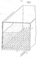
- the ticking is manufactured in several sections. First the ticking floor is made. That happens from one the outer wall of the liner forming sheet 2 or skin and a perforated tarpaulin or sheet 1 facing the bulk material. The perforation takes place before the floor is produced, for example with the aid of a needle roller.
- the two webs 1 and 2 lying one above the other and forming the ticking base are connected by welding.
- Heating wedges serve as welding devices. Welding is carried out with the aid of heat pulses or by means of heat contact welding and / or high-frequency welding.
- the webs can be connected by thread seams E. The thread seams can also replace the weld seams. The same applies to glued seams.
- FIG. 1 shows a ticking floor, the tarpaulin 1 and 2 are directly connected to each other by the seams 3.
- the seams run parallel to one another in the longitudinal direction of the inlet, so that there is a cavity between the tarpaulins 1 and 2 and the seams 3, which forms a line 4.
- the lines 4 more or less attain the round shape shown in FIG. 1 when air is blown in. When the bulk material is loaded, an approximately oval shape is created instead of the round shape, i.e. the lines 4 are flattened somewhat.
- the seams 3 between the lines 4 have the form of webs which connect the lines 4 to one another.
- the seams 3 are in operation on Shu claimed.
- the product of the load area per cm of seam length and the internal pressure of the cables 4 must not exceed the permissible peeling force at the seams or the permissible tear strength of the webs 1 and 2, which may be weakened by perforation when sewing Criteria for the permissible web width or seam width when dividing the ticking base.
- the lines 4 are supplied with compressed air according to FIG. 4 by one of the lines 4, which are connected to one another via a line 5 which runs transversely and is produced in the same way as the lines 4.
- the seams delimiting the line 5 differ from the seams 3 only in that they are interrupted at the connection point with the lines 4 in order to allow air to enter and exit the line 5 into the lines 4 and vice versa.
- the webs 1 and 2 forming in the tick bottom are directly connected to one another only at the outer edges of the web 1.
- the webs 1 and 2 are indirectly connected to one another by webs 6 between the outer edges.
- the webs 6 have a Z-shape in cross section and divide the cavity shown in FIG. 2 between the webs 1 and 2 into lines 7.
- the ticking base according to FIG. 2 is produced in the same way as that according to FIG. 1.
- 6 greater material thicknesses are used for the webs than for the webs 1 and 2. This has the advantage of greater strength between the lines 7.
- a web weakening associated with a perforation of the webs 6 can also be compensated for.
- the perforation or perforation which can be carried out like that of the web 1 with the aid of a needle roller, makes the webs permeable to air, so that a transverse line connecting the lines 7 to one another can be dispensed with.
- webs made of coarse-mesh and / or coated fabric can also be used. Insofar as a sealing of the webs then comes into consideration, this only takes place towards the web 2.
- the webs 6 are predominantly subjected to shear. This allows for higher internal pressures with the same dimensions compared to the lines 4 of Figure 1.
- perforated strips 8 are connected to the web 2.
- the connection is made as in FIGS. 1 and 2.
- the use of heating wedges is also advantageous. With the help of the heating wedges, the strips 8 can be welded onto the web 2 in such a way that the lateral ends of the strips 8 lie on the inside and, at the same time, welding of the strip part lying between the lateral ends is excluded.
- the advantage of the lines 9 shown in FIG. 3 is that the seams are only subjected to shear stress. In the embodiment according to FIG. 3, the distance between the individual lines 9 can be chosen as desired.
- All perforated ticking floors show favorable operating conditions, in particular a good pressure build-up if the perforation is particularly small. This also applies to only a partial soil load with bulk goods after the container has been partially emptied. Such small perforation holes are caused, for example, by needle pricks. According to the invention, inlets suitable for coal dust have 2-4 needle pricks per cm 2 .
- a polyethylene tape fabric (PE tape fabric) that is coated on both sides with 50 gr / m 2 polyethylene (PE) is preferably used as the ticking material.
- the tarpaulin 2 or 1 also forms the other walls of the inlet in addition to the floor.
- the number, size and position of the filler openings is equal to the number, size and position of the filler openings or gaps in the container roof. If necessary. can, if the loading facilities allow, work completely without filler openings 10. In this case, the emptying opening of the inlet also serves as a filling opening.
- filler funnels or filler neck 11 which are composed of tabs 12.
- the flaps 12 are fastened to the web 2 (on the ticking) like the web 1.
- FIG. 6 shows an overlap joint with overlapping ends 17 and 18.
- the joint according to FIG. 7 differs from the overlap joint by bluntly opposed ends 17 and 18, which are connected to one another by a strip of material 19. Both types of seam have the advantage of exclusive shear stress.
- all longitudinal seams are first welded or sewn.
- the last longitudinal seam can also be produced with the counter-face which considerably facilitates welding.
- Wooden slats or metal rails, which are removed from the ticking for the production of the transverse seams, serve as a counterpart.
- the cross seams are produced without a backing.
- the cross seams can be welded, glued and sewn.
- an insulating strip 20 is provided between the ends 17 and 18 to be connected to one another and the material part adjoining the end 17.
- the insulating strip forms an anti-adhesive. It prevents the seam formed by the two ends 17 and 18 from being connected to the material adjoining the end 17. An insulating strip is unnecessary if it is a question of sticky ticking materials or if an adhesive strip serves as a connecting means for the ends 17 and 18.
- Inliner production from hose sections is also partially possible. Inlays are inserted into the tube sections, which are either connected to the tube in the form shown in FIGS. 1-3 and then add to the tube to form a raised floor, or are merely attached to the tube in a dot or line shape. In the latter case, the loading of the bulk material causes the contact with the hose necessary to form lines 4 or 5 or 9.
- the filler neck 11 When installing the inlet according to the invention in a container, the filler neck 11 are guided through the container hatches and fastened there. It is sufficient to clamp between the hatch edge and hatch cover for fastening.
- the ticking is already fixed in its position.
- the ticking is then filled with air. This can be done through a separate filling opening or via the raised floor. If the double floor is used, one of the lines 4, which is provided with a connection leading to the outside, is connected to a compressed air hose 21.
- the compressed air hose is connected to a local compressed air network or a compressor or pressure container that can be transported with the container. In addition to the compressed air hose 21, further compressed air hoses can be connected to the ticking base or the lines 4. This is an advantage when there is a high demand for air.
- the inlet presses against the walls of the container due to the air pressure. A slight oversize of the inlet ensures that the seams of the inlet are not stressed by the application and the subsequent loading with the bulk material.
- the inlay cuboid shape shown in FIGS. 4 and 10 arises from the application to the container walls.
- the subsequent cuboid shape on the front wall of the container requires an excess of material from which triangles can be formed, the corners of which are designated 22, 23 and 24.
- folding precedes the filling of air or the filling of bulk goods.
- the triangular ends shown in FIGS. 11-13 are further folded around lines 22/24.
- the folded, triangular ends can be wrapped around the support rods, which are arranged at the top and bottom of the associated container side, for mounting or centering the inlet in the container.
- a simple tube can serve as a support rod.
- the end of the inlet opposite the end is intended for emptying the container and is attached to the emptying side of the container.
- the attachment is again done by wrapping a triangular end around a support rod. In the present case, the wrapping is limited to the upper, triangular end.
- the ticking is then fastened to the container at three edges or at three triangular ends projecting from these edges. This ensures that the inlet is centered in the container so that the bulk goods can be filled without damage.
- the centering can also be done using eyelets, hooks, bands.
- the eyelets are then arranged in the ticking and the hooks on the container or vice versa.
- the ticking can then be hung on the hooks of the container with its eyelets or hooked into the eyelets of the container with any hooks that may be present.
- tapes there is no need for hooks.
- the tapes are then attached to the ticking or in the container.
- the projecting ends of the inlet are also designed so that they can be looped through eyelets or other suitable openings in the container.
- the eyelets, hooks and straps can also be used to secure the ends wrapped around the support rods.
- the longitudinal seams of the inlet should run as parallel as possible to the longitudinal edges of the container and the transverse seams of the inlet should run as parallel as possible to the transverse edges of the container. This gives an extraordinarily good control for the necessary fixation of the inlet in the container.
- the unattached inlet end remaining after the three folded inlet ends have been fastened forms an emptying funnel and is closed with a clamping device designed as a clamping rail 25 in order to avoid undesired emptying.
- the operating position of the clamping rail is shown in Figure 11.
- the clamping rail consists of a bent spring wire or strips that can be screwed together.
- the triangular inlet end closed with the clamping rail is also brought into the folded position shown in FIG.
- the folded position of the triangular ends according to FIG. 13 corresponds to the position resulting when the associated supporting rods are wrapped or looped around.
- the support rods are wrapped around 180 °. Instead, multiple wrapping, which is equivalent to rolling up or winding up the triangular ends, can also take place.
- the winding also secures the triangular ends on the support arms.
- the support arms are expediently arranged to be rotatable and lockable in their respective rotational position. A simple embodiment of this arrangement is formed by support arms that are detachable for winding and attachable to the container for locking.
- ticking By winding, as well as with the help of eyelets, hooks and straps, the ticking can be easily clamped in the container and brought into the desired position.
- Advantageous voltage levels are the levels belonging to the areas and / or spatial diagonals of the inlet.
- the ticking at the ends does not require any special folding and the triangular ends can if necessary. can also be welded or separated.
- the inlet and container filling takes place in different variants depending on the design of the inlet or the suspension of the inlet in the container. If inlet ends are wrapped around supporting rods, the inlet is inflated with air before filling with bulk material. This ensures an even application of the inlet to the container walls and prevents creasing and the associated disadvantageous tensile stress on the inlet. The air supporting the inlet escapes during the filling process with bulk material. The filling process takes place against a slight overpressure in the inlet.
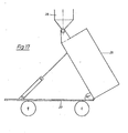
- the container 26 lined with the inlay is placed on a tilting chassis 27 in such a way that the emptying opening of the inlet and container or whose doors are up when tilted.
- This process is shown in Figure 17.
- a conventional motor vehicle trailer or truck with a tipping device is used as the tipping chassis 26.
- the ticking bottom does not need to be inflated during the filling process if the formation of a pouring cone can be disregarded.
- the bulk cone that forms reduces the degree of filling of the container or inlet. It is negligible if the container volume or ticking volume cannot be fully used due to the high specific bulk material weight and limited container loading capacity. With full usage possibility of influencing the filling level with the help of the inflatable ticking bottom.
- By inflating the ticking base an air cushion is created below the bulk material.
- the air pressure required for this is a maximum of 1.5 bar overpressure for conventional bulk goods with a specific weight of around 0.6 to / cbm. Inlet floor vibration is generated by pressure fluctuations.
- the container doors at the rear which belong to the emptying opening of the inlet, are opened.
- the inlet end provided with the emptying opening is folded out or pulled and cut off along line 29, provided that this end of the inlet has not yet been separated.
- the filler neck for filling in the same way as the inlet end according to FIG gur 17 is used.
- a bulkhead 30 in the container end.
- Two cross members 31 are provided for supporting or hanging the bulkhead 30.
- the arrangement of the crossbeams 31 is determined by the particular design of the container. Between the lower edge of Schott 30 and the container floor there is a free space of 40 - 50 cm in height across the entire width of the container. This free space is intended for container emptying.
- the inlet end to be cut is pulled through the free space and pushed onto the inlet nozzle of a conveyor unit for emptying and fastened there with a bag buckle.
- Suitable conveying units for emptying and filling include Nozzle conveyors, pressure conveyors, transfer stations, vacuum conveyors and blow-through rotary valves.
- the conveyor unit conveys the bulk material emerging from the container to any destination.
- the inlet end between the container and the filler neck of the conveyor unit is supported with a slide 32.
- the slide can be hooked into the cams or eyelets of the container housing, which are otherwise used to lock the container.
- the actual emptying that is to say the discharge of the bulk particles from the container, only begins after the clamping rail 25 has been removed Container 26 tilted.
- the emptying process is supported by blowing air into the bottom of the ticking.
- the blowing in of air causes air to escape into the bulk material and / or if the pressure fluctuations are generated, causing a ticking floor vibration.
- a valve in the air pressure line 21 leading to the ticking base with which valve air can be let out briefly by hand.
- the valve can be of the simplest type and can be operated manually.
- the vibration can be irregular.
- a container filled with coal dust for example, can be easily emptied even after a long transport and appropriate compression with the aid of the inlet according to the invention.
- An air consumption of 0.5 cbm / m2 container area and minute is sufficient.
- a constant exposure to air is not necessary.
- a switch-on time of 10 - 20% of the emptying time for the compressed air source is sufficient.
- the air consumption can be influenced favorably by a relatively large air pressure preload, which in a short time the necessary Ensures pressure build-up in the ticking floor.
- the pressure build-up is also accelerated with a reduction in the number of air outlet openings in the inlet floor.
Landscapes
- Engineering & Computer Science (AREA)
- Mechanical Engineering (AREA)
- Bag Frames (AREA)
- Filling Or Emptying Of Bunkers, Hoppers, And Tanks (AREA)
- Basic Packing Technique (AREA)
Applications Claiming Priority (2)
| Application Number | Priority Date | Filing Date | Title |
|---|---|---|---|
| DE2843906 | 1978-10-07 | ||
| DE19782843906 DE2843906A1 (de) | 1978-10-07 | 1978-10-07 | Fuellen und entleeren von containern |
Related Parent Applications (2)
| Application Number | Title | Priority Date | Filing Date |
|---|---|---|---|
| EP79103577A Division EP0010182B1 (fr) | 1978-10-07 | 1979-09-22 | Garniture tubulaire |
| EP79103577.7 Division | 1979-09-22 |
Publications (2)
| Publication Number | Publication Date |
|---|---|
| EP0036962A2 true EP0036962A2 (fr) | 1981-10-07 |
| EP0036962A3 EP0036962A3 (fr) | 1982-03-17 |
Family
ID=6051724
Family Applications (2)
| Application Number | Title | Priority Date | Filing Date |
|---|---|---|---|
| EP81101563A Withdrawn EP0036962A3 (fr) | 1978-10-07 | 1979-09-22 | Entrée sous forme de tuyau pour remplir et vider des récipients pour matières en vrac |
| EP79103577A Expired EP0010182B1 (fr) | 1978-10-07 | 1979-09-22 | Garniture tubulaire |
Family Applications After (1)
| Application Number | Title | Priority Date | Filing Date |
|---|---|---|---|
| EP79103577A Expired EP0010182B1 (fr) | 1978-10-07 | 1979-09-22 | Garniture tubulaire |
Country Status (2)
| Country | Link |
|---|---|
| EP (2) | EP0036962A3 (fr) |
| DE (2) | DE2843906A1 (fr) |
Cited By (1)
| Publication number | Priority date | Publication date | Assignee | Title |
|---|---|---|---|---|
| WO1984003684A1 (fr) * | 1983-03-16 | 1984-09-27 | Medox Ltd | Structure pour le transport de produits deversables et autres |
Families Citing this family (4)
| Publication number | Priority date | Publication date | Assignee | Title |
|---|---|---|---|---|
| DE3131867A1 (de) * | 1981-08-12 | 1983-02-24 | Ruhrkohle-Carborat GmbH, 4152 Kempen | "containerinlett aus beschichteten baendchengeweben" |
| DE3834339A1 (de) * | 1988-10-08 | 1990-04-12 | Ulrich Reissmann | Vorrichtung zum entladen von behaeltern |
| GB2227482A (en) * | 1989-01-26 | 1990-08-01 | Exprocad Services Ltd | Fluidising bulk particulate material |
| AU623305B1 (en) * | 1991-09-05 | 1992-05-07 | Mulawa Trading Co Pty Ltd | Container liner |
Family Cites Families (12)
| Publication number | Priority date | Publication date | Assignee | Title |
|---|---|---|---|---|
| DE927437C (de) * | 1952-04-30 | 1955-05-09 | Moeller Johannes | Vorrichtung zum Auflockern und Foerdern staubfoermigen und feinkoernigen Gutes durch in das Gut eingeblasene Luft |
| DE1709095U (de) * | 1953-07-07 | 1955-10-20 | Klinger K G | Vorrichtung zur auflockerung von pulverfoermigen oder staubfoermigen guetern in druck- und drucklosen behaeltern. |
| US2805896A (en) * | 1954-02-23 | 1957-09-10 | Bituminous Coal Research | Pneumatic material handling system and apparatus |
| US2930512A (en) * | 1955-07-01 | 1960-03-29 | Paton Holdings Ltd | Apparatus for holding and discharging free-flowing solid materials |
| US2943891A (en) * | 1956-12-07 | 1960-07-05 | Paton Hamilton Neil King | Unloading floor mat |
| DE1121799B (de) * | 1957-01-24 | 1962-01-11 | Franz Xaver Wortmann Dr Ing | Verfahren zur Herstellung von poroesen Formkoerpern aus Kunststoff |
| DE1865881U (de) * | 1960-08-16 | 1963-01-17 | Luther Werke Luther & Jordan | Fahrbarer kipptank fuer staubfoermiges bzw. mehliges gut, insbesondere backmehl. |
| DE1923804A1 (de) * | 1968-05-25 | 1969-12-04 | Denki Onkyo Co Ltd | Verfahren zum Herstellen veredelter Polymere aus Vinylverbindungen |
| DE1923344A1 (de) * | 1969-05-07 | 1970-11-19 | Berestovoj Anatolij Michajlovi | Verfahren zum Ausladen von Schuettguetern aus Behaeltern,die in ihrem Unterteil mit elastischen Ablaufwaenden ausgestattet sind,und Vorrichtung zur Durchfuehrung dieses Verfahrens |
| DE2012071A1 (de) * | 1970-03-13 | 1971-09-23 | International Ferry Freight Ltd., Ilford, Essex (Großbritannien) | Transportcontainer |
| IT970706B (it) * | 1972-09-20 | 1974-04-20 | Montedison Spa | Apparecchiatura costituita da un saccone in plastica e da una at trezzatura per la sua sistemazio ne su grandi contenitori partico larmente indicata per il carico e scarico di materiali sfusi incoe renti |
| GB1580806A (en) * | 1976-06-01 | 1980-12-03 | Ici Ltd | Liner for container |
-
1978
- 1978-10-07 DE DE19782843906 patent/DE2843906A1/de not_active Withdrawn
-
1979
- 1979-09-22 EP EP81101563A patent/EP0036962A3/fr not_active Withdrawn
- 1979-09-22 DE DE7979103577T patent/DE2964363D1/de not_active Expired
- 1979-09-22 EP EP79103577A patent/EP0010182B1/fr not_active Expired
Cited By (1)
| Publication number | Priority date | Publication date | Assignee | Title |
|---|---|---|---|---|
| WO1984003684A1 (fr) * | 1983-03-16 | 1984-09-27 | Medox Ltd | Structure pour le transport de produits deversables et autres |
Also Published As
| Publication number | Publication date |
|---|---|
| EP0010182A1 (fr) | 1980-04-30 |
| DE2964363D1 (en) | 1983-01-27 |
| DE2843906A1 (de) | 1980-04-17 |
| EP0010182B1 (fr) | 1982-12-22 |
| EP0036962A3 (fr) | 1982-03-17 |
Similar Documents
| Publication | Publication Date | Title |
|---|---|---|
| DE60001621T2 (de) | Behälterauskleidung mit Verschiebemitteln zur Erleichterung des Entladens des Behälterinhalts | |
| DE69903288T2 (de) | Innensack für flexiblen schüttgutbehälter | |
| DE69209421T2 (de) | Flexible Behälter | |
| DE2622051A1 (de) | Container mit einer auskleidung zur aufnahme von schuettgut | |
| DE1486559B2 (de) | Mehrlagiger lager- und versandbehaelter | |
| DE69220227T2 (de) | Frachtbehälter und Verfahren zu dessen Entladung | |
| DE3207322C2 (de) | Großsack mit einem doppelwandigen Außensack und einem eingelegten Innensack | |
| EP0226057B1 (fr) | Machine de remplissage de sacs | |
| DE3310721A1 (de) | An traggestellen aufhaengbarer flexibler silo | |
| EP0444261B1 (fr) | Récipient d'emballage flexible en forme de sac, fabriqué à partir d'une feuille de matière plastique | |
| EP0008392B1 (fr) | Véhicule servant à transporter soit des objets ayant une forme définie, soit des chargements pouvant s'écouler | |
| EP0036962A2 (fr) | Entrée sous forme de tuyau pour remplir et vider des récipients pour matières en vrac | |
| EP0992433A2 (fr) | Procédé et dispositif de transport, de vérification, de remplissage et de fermeture de sacs | |
| WO2012048837A1 (fr) | Machine d'emballage et procédé de remplissage de sacs | |
| EP0727365B1 (fr) | Conteneur flexible pour matériaux en vrac et/ou coulables | |
| DE2552438B1 (de) | Ventilsack | |
| DE3130467C2 (fr) | ||
| DE2852578A1 (de) | Behaelter fuer schuettgut und verfahren zum entladen eines derartigen behaelters | |
| EP0904978B1 (fr) | Espace de chargement pour les produits en vrac pour des véhicules de transport. | |
| DE8628334U1 (de) | Vorrichtung zum Lagern und Ausgeben von mehligem bis staubförmigem Schüttgut | |
| DE2605122C3 (de) | Schüttgutbehälter mit flexiblen Wandungen | |
| DE60216326T2 (de) | Maschine und verfahren zum erhalt eines grossen schlauchs aus einem flexiblen kunststoffmaterial, das in form eines balgs gefaltet ist | |
| DE3403996C2 (fr) | ||
| DE2602486C2 (de) | Pneumatische Austragsvorrichtung für pulverförmiges, vorzugsweise schwer fließfähiges Schüttgut | |
| DE3346162A1 (de) | Fahrzeug fuer den wahlweisen transport von guetern fester raumform oder von fliessfaehigen guetern |
Legal Events
| Date | Code | Title | Description |
|---|---|---|---|
| PUAI | Public reference made under article 153(3) epc to a published international application that has entered the european phase |
Free format text: ORIGINAL CODE: 0009012 |
|
| AC | Divisional application: reference to earlier application |
Ref document number: 10182 Country of ref document: EP |
|
| AK | Designated contracting states |
Designated state(s): BE DE FR GB NL |
|
| PUAL | Search report despatched |
Free format text: ORIGINAL CODE: 0009013 |
|
| AK | Designated contracting states |
Designated state(s): BE DE FR GB NL |
|
| 17P | Request for examination filed |
Effective date: 19820201 |
|
| STAA | Information on the status of an ep patent application or granted ep patent |
Free format text: STATUS: THE APPLICATION IS DEEMED TO BE WITHDRAWN |
|
| 18D | Application deemed to be withdrawn |
Effective date: 19830913 |
|
| RIN1 | Information on inventor provided before grant (corrected) |
Inventor name: STRESE, GERHARD, ING. |