EP0037228A2 - Drehbarer Raffkopf mit sechs Rädern - Google Patents
Drehbarer Raffkopf mit sechs Rädern Download PDFInfo
- Publication number
- EP0037228A2 EP0037228A2 EP81301230A EP81301230A EP0037228A2 EP 0037228 A2 EP0037228 A2 EP 0037228A2 EP 81301230 A EP81301230 A EP 81301230A EP 81301230 A EP81301230 A EP 81301230A EP 0037228 A2 EP0037228 A2 EP 0037228A2
- Authority
- EP
- European Patent Office
- Prior art keywords
- shirring
- drive
- shaft
- output shaft
- wheels
- Prior art date
- Legal status (The legal status is an assumption and is not a legal conclusion. Google has not performed a legal analysis and makes no representation as to the accuracy of the status listed.)
- Withdrawn
Links
Images


Classifications
-
- A—HUMAN NECESSITIES
- A22—BUTCHERING; MEAT TREATMENT; PROCESSING POULTRY OR FISH
- A22C—PROCESSING MEAT, POULTRY, OR FISH
- A22C13/00—Sausage casings
- A22C13/02—Shirring of sausage casings
Definitions
- This invention relates in general to a six- wheel spinning shirring head for shirring tubular films.
- Tubular films of collagen and cellulose are used extensively as sausage casings. These are initially formed as continuous tubes which are rolled flat to form "reels". The tubular films are then opened over a mandrel and are shirred on that mandrel so that many feet of the tubular casings may be formed into a stick having a length on the order of 30 to 45 cm.
- Shirring is effected by rotating wheels which normally are provided with lugs which cooperate with one another so as to effect a most efficient folding of the tubular films.
- Such prior apparatus is generally disclosed in the U.S. Patents 3,454,981 and 3,461,484.
- This invention most particularly relates to a shirring head which has a plurality of shirring wheels disposed in circumferentially spaced relation about an associated mandrel.
- the shirring wheels are mounted for individual rotation in unison, and further for rotation as a unit about the axis of the shirring mandrel.
- Such a shirring head is broadly disclosed in U.S. Patent 4,085, 483.
- This invention most particularly has to do with the number of shirring wheels and their arrangement so that the most casing can be shirred in the least length of strand with the least damange to the film.
- the theoretical optimum is an infinite number of infinitesimal thickness disposed equiangularly about the axis of the mandrel. This is so because a tangential linear force is being used to produce a rounded configuration. Since the element for transmission of the force has a thickness, it must of necessity have a curvature at its end whereby the force is transmitted. But the velocity of points along the curvature varies in proportion to the distance of the points from the axis of rotation. Thus, the points at the extremities of the arc travel faster than the point at the center of the arc, and furthermore the points at the extremities intersect radial lines from the mandrel to the outer diameter of the strand.
- Secondary pleats are those which are widest at the bore of the strand and fade to no fold at the outer diameter of the strand. Such pleats are inherent and occur in all strands having the helical pleat pattern of Pat. 3,461,484, including those so described by U. S. Patent 4,001,914.
- the goals then of this invention are to provide an apparatus which can produce a shirred strand of casing having the least possible damage done during shirring, but which also produces uniform folding of the secondary pleats so that higher density and more estehtical- ly appealing strands are also produced.
- an apparatus was provided with six wheels of about 1.27 cm. width and of known composition mounted uniquely on six unique angle drives in turn mounted on a rotatable plate with power inputs both to the shirring wheels and to the plate in a manner wherein the rotation of the plate could be changed at will without affecting the rotation rate of the wheels.
- a novel drive system employing a differential gear train with two inputs and two outputs was provided. One input drives the wheels through its output. The other input drives the plate through its output. As the plate input is changed, the wheel output of the differential changes to compensate for the fact that the plate rotation changes the effective wheel rotation. With this arrangement, the head can be caused to spin in either direction at any rate without altering the wheel input and with the wheel speed remaining constant.
- the shirring wheels are each carried by a right angle drive which is mounted on a supporting head.
- Each right angle drive is of such a construction wherein the respective shirring wheel carried thereby does not interfere with the next adjacent right angle drive, and thus as many as six shirring wheels may be mounted around a small diameter mandrel and it being feasible to increase the number of shirring wheels when the diameter of the mandrel increases.
- Each right angle drive includes a simple housing which has rotatably journalled therein a drive shaft.
- the drive shaft carries at its end within the housing a gear which is meshed with a further gear disposed at right angles thereto and which further gear is secured to a mounting collar for the respective shirring wheel.
- the further gear and mounting collar are rotatably journalled on a fixed shaft.
- the fixed shaft projects a minimal distance to one side of the housing, and thus mounts the respective shirring wheel immediately alongside the housing parallel to the driving shaft therefor.
- the housing may occupy the space between adjacent shirring wheels.
- the driving shaft has that end thereof provided with the gear within the housing supported by a pin which is journalled within the free end thereof and which pin serves the dual function of anchoring the fixed shaft against movement relative to the housing.
- Another feature of the invention is the specific construction of the shirring head wherein the supporting head is provided with a supporting plate and the entire shirring head is mounted for rotation about the axis of the shirring mandrel by a bearing located in the general plane of the supporting plate.
- the radially inner part of the supporting plate is provided with an axially extending support sleeve which serves to mount for rotation the drive means for the individual right angle drives.
- the right angle drives extend to one side of the supporting plate and the drive means therefor are disposed on the opposite side of the supporting plate.
- a further and important feature of the invention is the provision of a differential drive for modifying the speed of rotation of the shirring wheels in accordance with the direction and speed of rotation of the entire shirring head about the shirring mandrel.
- a separate drive is provided for rotating the shirring head and for rotating in unison the shirring wheels about their individual axes.
- These separate drives are driven from a differential drive unit which includes two input shafts and two output shafts.
- the first input shaft is directly coupled to a first of the output shafts and serves to drive the shirring head in a selected rotational direction and at a selected speed.
- the second of the input shafts is coupled to a second of the output shafts by way of a differential gearing.
- the second output shaft is coupled to the individual shirring wheels through their right angle drives for rotating the shirring wheels in the same direction and at the same speed.
- the second input shaft is coupled to the second output shaft by a differential gearing which also receives an input thereto from the first input shaft.
- the first input shaft has a direct control over the speed of rotation of the second output shaft.
- the shirring apparatus conventionally includes a frame generally identified by the numeral 22 and including a horizontal frame section 24 which is supported by suitable legs 26.
- the legs 26 at one end of the frame 22 carry a support 28 for a reel 30 of the casing 32.
- the casing 32 extends over a measuring roll 34 against which it is held by a squeeze roll 36.
- the casing 32 which is flat and is in the form of reelstock, is conventionally inflated as at 38.
- the frame 22 includes a superstructure 40 which carries a shirring head, generally identified by the numeral 42, formed in accordance with this invention.
- a shirring mandrel 44 is mounted within the shirring head 42 and has a leading end immediately adjacent the point where the casing is inflated so as to receive the inflated casing.
- the inflated casing is moved along the shirring mandrel 44 by a pair of feed belts 46, 48.
- a motor 50 is provided for driving both the measuring roll 34 and the feed belts 46 and 48 in a conventional manner.
- a combined strand spinner and holdback mechanism 52 Downstream of the shirring head 42 is a combined strand spinner and holdback mechanism 52.
- clamps 54 Downstream of the holdback device 52 are suitable clamps 54 of which only one is shown.
- the clamps 54 support the mandrel 44 in a conventional manner.
- a compression member 56 Between the clamps 54 is a compression member 56 which is mounted on rods 58 extending above the frame member 24 from the superstructure.
- the shirring head 42 is carried by an upstanding frame member 60 which forms part of the superstructure 40.
- the frame member 60 as is best shown in Figure 3, has an annular flange 62 which defines a seat 64 for an outer race 66 of the bearing assembly 68.
- the bearing assembly 68 also includes an inner race 70 and a plurality of bearing rollers 72. The bearing assembly is so constructed wherein it permits rotation of the shirring head 42 within the frame member 60 while maintaining the axial position of the shirring head 42.
- outer race 66 is removably mounted within the flange 62 by means of a retaining collar 74.
- the shirring head 42 includes generally a supporting head identified by the numeral 76.
- the supporting head 76 includes a centrally positioned supporting plate 78 which lies in the same common plane as the frame member 60 and has an outer flange portion 80.
- the outer flange portion 80 has seated therein the inner race 70 which is secured in place by means of an annular plate 82.
- the supporting head 76 also includes a radially inner tubular support member or sleeve 84 which extends through the supporting plate 78 and is fixedly secured thereto.
- the sleeve 84 has an internal diameter of a size freely to receive the shirring mandrel 44 and an associated tubular film to be shirred.
- the support sleeve 84 has rotatably journalled therein a drive member 86 by way of bearings 88 and 90.
- the drive member 86 is axially positioned on the support sleeve 84 by a thrust bearing 92 which engages the supporting plate 78, and a thrust bearing 94 which engages a positioning flange or collar 96 which is adjustably secured on the support sleeve.
- the drive member 86 has an intermediate, radially outwardly extending rib 98 which is generally aligned with the inner portion of the annular plate 82 and has engaged therewith a seal 100 carried by the annular plate 82.
- a seal between the drive member 86 and the support sleeve 84 is effected by a sealing element 102 disposed between the bearings 90 and 94.
- each of the assemblies 104 includes a shirring wheel 106 which, although it has been illustrated with a continuous perimeter, will be of the toothed type conventionally known in the art. As is clearly shown in Figure 2, there are six shirring wheels 106 and the shirring wheels are equally spaced about the shirring mandrel 44.
- the mounting of the shirring wheels 106 is such that adjacent shirring wheels are in substantially touching relation and the relationship of the number of shirring wheels, the thickness of the shirring wheels, and the circumference of the shirring mandrel present a shirring surface substantially entirely around the circumference of the shirring mandrel.
- each right angle drive assembly includes a simple housing which has rotatably journalled therein a drive shaft.
- the drive shaft carries at its end within the housing both a bevel gear on the outer diameter and a roller bearing cavity within the shaft.
- the bevel gear meshes with a further bevel gear at a right angle thereto.
- the cavity receives a pin which acts as a bearing shaft for rollers displaced within the cavity.
- the further (driven) bevel gear is made an integral part of a shirring wheel hub which hub has a cavity for a ball bearing and which bevel gear has a cavity for roller bearings. Both bearings are held in place by a shaft fixed in the housing immediately adjacent the bevel gear. In this manner, the driven bevel gear is supported rigidly and the deflection and consequent backlash are negligible even under heavy loading.
- Each assembly 104 includes a housing 108 of a generally triangular cross section, as is shown in Figure 7. At one end the housing 108 is provided with mounting flanges 110 and 112 which receive fasteners 114 which secure the housing 108 to the adjacent face of the supporting plate 78.
- That part of the housing 108 facing the supporting plate 78 is hollow, having a bore 116 formed therein as is best shown in Figure 4.
- a reduced diameter bore 118 extends from the inner end of the bore 116 through that end of the housing 108 disposed remote from the supporting plate 78.
- the bore 118 is disposed coaxial with the bore 116.
- a drive shaft 120 is rotatably journalled within the bore 116 by way of a pair of double row ball bearings 122. Further, the end of the drive shaft 120 within the housing 108 is supported by means of an anchoring pin 124 which extends through the bore 118 and into the bore 116. To this end, the right end of the drive shaft 120, as viewed in Figure 4, is provided with a bore 126 into which the pin 124 projects. A bearing 128 is disposed between the drive shaft 120 and the pin 124 so as to permit the pin 124 to support the drive shaft 120 free end. This arrangement allows a heavy load to be imposed with little deflection and hence little backlash.
- the free end of the drive shaft 120 carries a bevel gear 130 which is secured to the drive shaft 120 by a pin 132.
- the opposite end of the bore 116 is sealed by a ring seal 133 which surrounds the drive shaft 120.
- one side of the housing Adjacent the end of the housing 108 disposed remote from the supporting plate 78, one side of the housing is provided with a large diameter bore 134, as is best shown in Figure 5.
- a smaller diameter bore 136 extends transversely through the housing 108 in coaxial relationship with the bore 134.
- a first supporting shaft 138 extends through the bore 136 into and out through the bore 134.
- the bore 136 intersects the bore 118 at right angles thereto and has a bore 140 therethrough in alignment with the bore 118 so that the retaining pin 124 may extend through the fixed shaft 138 and retain it in position in the manner clearly shown in Figures 4 and 5.
- the axes of the drive shaft 120-and the fixed shaft 138 lie in a common plane with the axis of the fixed shaft being disposed at right angles to the axis of the drive shaft.
- the fixed shaft 138 has rotatably journalled thereon a shirring wheel unit, generally identified by the numeral 142.
- the shirring wheel unit 142 includes one of the afore-described shirring wheels 106 and includes a mounting collar 144 having a hub portion 146.
- the hub portion 146 serves the dual function of centering the shirring wheel 106 and mounting a bearing assembly 148, the bearing assembly 148 being carried by the fixed shaft 138.
- the mounting collar or flange 144 carries a bevel gear 150 which is meshed with the bevel gear 130.
- the bevel gear 150 is further rotatably journalled on the fixed shaft 138 by means of a bearing assembly 152.
- a seal 154 is carried by the mounting flange and engages the fixed shaft 138 between the bearing units 152 and 148.
- the mounting flange 144 generally closes the bore 134 and has projecting from one face thereof a sleeve portion 156 which is telescoped within the bore to form a general seal therewith.
- the shirring wheel 106 is preferably formed of an elastomeric material and is molded on a hub 158 which has a toothed periphery to facilitate the interlocking of the hub with the elastomer.
- the hub 158 is angularly adjustably positioned relative to the mounting flange 144 and the gear 150 by providing the hub 158 with arcuate slots 160 through which securing fasteners 162 extend.
- the shirring wheel 106 is clamped against the mounting flange 144 by means of a collar 164 with the fasteners 162 having heads engaging the collar 164 and the opposite ends of the fasteners 162 being threaded into the mounting flange 144.
- the right angle drive assemblies 104 are so constructed to occupy a minimum of space and thus permit the mounting of a large number of shirring wheels 106 in a very confined space.
- Such a mounting and drive arrangement for each shirring wheel 106 permits shirring wheels of conventional thickness to be disposed in substantially touching relation so as to present a shirring surface substantially continuously about the circumference of the shirring mandrel 44.
- the peripheral face of the shirring wheel 106 is machined so as to be arcuate as at 166 to correspond to the periphery of the shirring mandrel 44 while the opposite side faces of the shirring wheel are tapered as at 168 to provide clearance relative to adjacent shirring wheels.
- the drive shaft 120 may extend through the supporting plate 78 and further be supported for rotation by means of the bearing 172.
- the left end of each drive shaft 120 is provided with a drive gear 176 which is fixedly secured to the drive shaft 120 in driving relation by means of a key 178.
- the previously described drive member 86 is provided with a ring gear 180 aligned with the gears 176 for simultaneously driving all of the drive shafts 120 and rotating all of the shirring wheels 106 in the same direction and at the same speed upon rotation of the drive member 86 relative to the supporting head 76.
- the drive member 86 carries on the side of the rib. 98 remote from the gear 99 a toothed sprocket 182 for a toothed drive belt. In this manner the drive member 99 may be rotated independently of the supporting head 76 so as directly to drive the shirring wheels 106 about their relatively fixed shafts 138.
- the supporting head 76 is provided on the side thereof remote from the cover plate 82 with the toothed sprocket 184 for a further drive belt.
- the toothed sprocket 184 serves to effect rotation of the supporting head 76.
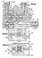
- the shirring head 42 is driven by means of a differential drive unit, generally identified by the numeral 186, which is mounted on the top of the superstructure 40 as is clearly-shown in Figures 2 and 3.
- the differential drive unit 186 includes a first output shaft 188 having thereon a drive sprocket 190 aligned with the sprocket 184 and drivingly connected thereto by means of a drive belt 192.
- the differential drive unit 186 also includes a second output shaft 194 which carries a drive sprocket 196 which is aligned with the drive sprocket 182 and is drivingly connected thereto by means of a drive belt 198.
- drive belts 192 and 198 are of the toothed type so as to provide for an interlocking engagement with their respective sprockets, as is clearly shown in Figure 2 so that there is a positive driving of the components of the shirring head 42.
- the differential drive unit 186 includes a suitable housing 200 which is generally shown in Figures 8-10 and includes a removable cover 202.
- the housing 200 includes a bottom wall 204 having extending upwardly from opposite sides thereof side walls 206 and 208.
- the housing further includes an end wall 210 and a stepped end wall 212 as is clearly shown in Figure 8.
- the first output shaft 188 extends substantially the full length of the housing 200 and opens out through the stepped end wall 212.
- the shaft 188 is supported by suitable bearings 214 and 216 which are carried by projections 218 and 220 on the end walls 210 and 212, respectively.
- the second output shaft 194 is arranged in parallel relation to the output shaft 188 and also extends generally the full length of the housing 200 and projects out through the stepped end wall 212.
- the step - ing of the end wall 212 permits the drive sprockets 190 and 196 to be offset generally along the axis of the shirring machine, as is clearly shown in Figure 3.
- the shaft 194 is rotatably journalled in bearings 222 and 224 carried by inwardly directed projections 226 and 228 of the end walls 210 and 212, respectively.
- the end wall 206 has extending therethrough a first input shaft 230 which is rotatably journalled in suitable bearings 232 carried by an outward projection 234 of the side wall 206.
- the input shaft 230 carries a drive sprocket 236 which is driven by way of a drive belt 238 of a suitable drive motor (not shown).
- the inner end of the input shaft 230 carries a bevel gear 239 which is meshed with a bevel gear portion 240 of a gear member 242.
- the gear member 242 is suitably rotatably journalled on the output shaft 194 for rotation relative thereto and has a spur gear portion 244 which is meshed with a direction reversing gear 246 which is rotatably journalled on a shaft defining shoulder bolt 248 carried by the end wall projection 218.
- the gear 246 is in turn meshed with a gear 250 which is suitably keyed onto the output shaft 188.
- the gears 246 and 250 are maintained in alignment by means of a thrust plate 252 which is positioned by the shoulder bolts 248.
- a further suitable thrust plate 254 is positioned between the gears 246 and 250 and the inner end of the projection 218.
- a second input shaft 256 also extends through the side wall 206 and is rotatably journalled in bearings 258 carried by an outwardly projecting projection 260.
- An outer end of the shaft 256 carries a drive sprocket 262 which is driven in any suitable manner by way of a toothed belt (not shown) from a power source.
- the inner end of the shaft 256 is provided with a bevel gear 264 in the same manner as the shaft 230. It is to be noted at this time that the gears 239 and 264 are positioned relative to the side wall 206 by way of thrust bearings 266 and 268, respectively.
- a gear member 270 is rotatably journalled on the output shaft 194 and has a first bevel gear portion 272 meshed with the bevel gear 264 so as to be driven thereby.
- the gear member 242 has a bevel gear portion 274 and the gear member 270 has a bevel gear portion 276 which are disposed generally in opposed relation and are mounted concentric with the shaft 194 for rotation thereabout.
- the bevel gear portions 274 and 276 form parts of a differential gearing generally identified by the numeral 278.
- the differential gearing 278 includes a drive sleeve 280 which is fixed to the output shaft 194 for driving the same.
- the sleeve 280 has extending therefrom in diametrically opposite relation a pair of shafts 282 on which there are mounted for rotation bevel gears 284.
- Each of the bevel gears 284 meshes with the bevel gear portions 274 and 276.
- bevel gears 284 are journalled on the shafts 282 by means of bearings 286 and are axially positioned by means of thrust bearings 288 together with a retaining ring 290.
- the differential gearing 278 is positioned on the output shaft 194 by the gear members 242 and 270 being journalled on the shaft 194 by way of suitable bearing means 292 and being axially positioned by means of thrust bearings 294 and retainers 296.
- the input shaft 230 directly controls the rotation of the supporting head.76 so as directly to control the rotation of the shirring wheels 106 about the axis of the shirring mandrel 44.
- the input shaft 256 directly controls the rotation of the shirring wheels 106 about their individual fixed shafts 138 so that when the supporting head 76 is held stationary, the shirring wheels 106 will function in the normal manner.
- the direction of head spin may advantageously be directed oppositely to control secondary pleating better.
- the amount of spin required to control secondary pleating varies with shirring speed as well as casing size.
- the optimum spin and direction are also affected by the contact angle of the shirring element. It thus becomes evident that a system whereby spin rate and direction can be carried at will 5 without distrubing shirr rate is highly desirable.
- the output shaft rotational speed is doubled.
- the cross gear 284 does not rotate at all and the assemblies 242 and 272 and cross gears 284 rotate as a unit.
- the input shaft speed on one side can be different from that on the other side, in which case the output speed can be varied at will merely by changing the speed and/or direction of an input.
- the gears 176 are caused to rotate around the sun gear 99 in the ratio between the gears 176 and 99.
- the gear ratios are selected so that a change in output from the head drive is exactly compensated for in the wheel drive by the differential.
- the net RPM.at the wheels did not change. It is 900 RPM with the head input zero, 100 or 200 RPM. This is so even when the head drive RPM is greater than the wheel drive RPM as shown in parentheses.
- wheel drive input pulley 262 for differential must always be counterclockwise (CCW) looking at pulley 182. This direction produces the prop-, er rotation of the wheels if head is not spinning.
- CCW counterclockwise
- wheel RPM is subtracted at head, but an equivalent amount is added at differential.
- wheel RPM is increased by the head, but an equivalent amount of RPM is subtracted at the differential. The net result is no change in wheel speed whether the head is spun or not in either direction.
- shirring head 42 has been specifically illustrated in conjunction with other well known shirring apparatus, it is to be understood that the shirring head may be utilized in any conventional shirring apparatus environment and is not restricted to the specific environment illustrated in Figure 1.
Landscapes
- Life Sciences & Earth Sciences (AREA)
- Engineering & Computer Science (AREA)
- Wood Science & Technology (AREA)
- Zoology (AREA)
- Food Science & Technology (AREA)
- Grinding And Polishing Of Tertiary Curved Surfaces And Surfaces With Complex Shapes (AREA)
- Finish Polishing, Edge Sharpening, And Grinding By Specific Grinding Devices (AREA)
- Processing And Handling Of Plastics And Other Materials For Molding In General (AREA)
- Specific Conveyance Elements (AREA)
Applications Claiming Priority (2)
| Application Number | Priority Date | Filing Date | Title |
|---|---|---|---|
| US136658 | 1980-04-02 | ||
| US06/136,658 US4374447A (en) | 1980-04-02 | 1980-04-02 | Six-wheel spinning shirring head |
Publications (2)
| Publication Number | Publication Date |
|---|---|
| EP0037228A2 true EP0037228A2 (de) | 1981-10-07 |
| EP0037228A3 EP0037228A3 (de) | 1982-02-24 |
Family
ID=22473795
Family Applications (1)
| Application Number | Title | Priority Date | Filing Date |
|---|---|---|---|
| EP81301230A Withdrawn EP0037228A3 (de) | 1980-04-02 | 1981-03-23 | Drehbarer Raffkopf mit sechs Rädern |
Country Status (14)
| Country | Link |
|---|---|
| US (1) | US4374447A (de) |
| EP (1) | EP0037228A3 (de) |
| JP (1) | JPS56154947A (de) |
| AU (1) | AU535089B2 (de) |
| BR (1) | BR8101982A (de) |
| CA (1) | CA1166416A (de) |
| DD (1) | DD157880A5 (de) |
| DK (1) | DK147881A (de) |
| ES (1) | ES8205106A1 (de) |
| FI (1) | FI811011L (de) |
| GB (1) | GB2073575B (de) |
| PL (1) | PL230482A1 (de) |
| YU (1) | YU80181A (de) |
| ZA (1) | ZA811837B (de) |
Cited By (2)
| Publication number | Priority date | Publication date | Assignee | Title |
|---|---|---|---|---|
| EP0073321A3 (en) * | 1981-07-17 | 1983-04-20 | Union Carbide Corporation | High coherency shirred casings |
| DE4436911A1 (de) * | 1994-10-15 | 1996-04-18 | Eichel Packomat Gmbh | Vorrichtung zum axialen Raffen von Schlauchfolien |
Families Citing this family (4)
| Publication number | Priority date | Publication date | Assignee | Title |
|---|---|---|---|---|
| US5173074A (en) | 1991-10-15 | 1992-12-22 | Viskase Corporation | Method and apparatus for severing shirred tubular food casing, and article |
| US7507150B2 (en) * | 2004-08-23 | 2009-03-24 | Visko Teepak Belgium Nv | Shirred casing |
| US8978476B2 (en) * | 2012-11-05 | 2015-03-17 | General Electric Company | Ultrasonic signal coupler |
| CN104742355B (zh) * | 2013-12-30 | 2017-03-08 | 中国科学院沈阳自动化研究所 | 一种火腿肠塑料肠衣双轮打褶机 |
Family Cites Families (10)
| Publication number | Priority date | Publication date | Assignee | Title |
|---|---|---|---|---|
| LU33675A1 (de) | 1954-07-07 | |||
| US2983949A (en) * | 1959-07-22 | 1961-05-16 | Union Carbide Corp | Apparatus for shirring sausage casings |
| US3310833A (en) * | 1963-10-07 | 1967-03-28 | Tee Pak Inc | Shirring apparatus |
| FR96372E (de) | 1967-12-27 | 1972-06-16 | ||
| US3986230A (en) * | 1973-02-27 | 1976-10-19 | Hoechst Aktiengesellschaft | Apparatus for shirring tubular casings |
| US4176204A (en) * | 1974-01-25 | 1979-11-27 | Bruno Winkler | Process for shirring tubular films and product thereof |
| DE2403470C3 (de) * | 1974-01-25 | 1981-02-12 | Naturin-Werk Becker & Co, 6940 Weinheim | Vorrichtung zum Raffen von Schlauchfolien aus tierischer Hautfasermasse |
| DE2646848C2 (de) | 1976-10-16 | 1983-08-11 | Günter 6080 Groß-Gerau Kollross | Vorrichtung zum axialen Raffen von dünnwandigen Schlauchmaterial, insbesondere Kunstdarm für die Wurstherstellung |
| FI64497C (fi) * | 1976-10-16 | 1983-12-12 | Guenter Kollross | Anordning foer axiell hopstoetning av ett tunnvaeggigt slangmaterial skaerskilt en konsttarm foer korvtillverkning |
| DE2944623C2 (de) * | 1979-11-05 | 1983-10-13 | Günter 6080 Groß-Gerau Kollross | Vorrichtung zum axialen Raffen von synthetischem Schlauchmaterial zur Weiterverarbeitung insbesondere auf Wurstfüllautomaten |
-
1980
- 1980-04-02 US US06/136,658 patent/US4374447A/en not_active Expired - Lifetime
-
1981
- 1981-01-27 CA CA000369378A patent/CA1166416A/en not_active Expired
- 1981-03-19 ZA ZA00811837A patent/ZA811837B/xx unknown
- 1981-03-23 EP EP81301230A patent/EP0037228A3/de not_active Withdrawn
- 1981-03-23 GB GB8108994A patent/GB2073575B/en not_active Expired
- 1981-03-24 AU AU68689/81A patent/AU535089B2/en not_active Ceased
- 1981-03-27 YU YU00801/81A patent/YU80181A/xx unknown
- 1981-04-01 BR BR8101982A patent/BR8101982A/pt unknown
- 1981-04-01 DK DK147881A patent/DK147881A/da not_active IP Right Cessation
- 1981-04-01 JP JP4923281A patent/JPS56154947A/ja active Pending
- 1981-04-01 FI FI811011A patent/FI811011L/fi not_active Application Discontinuation
- 1981-04-02 DD DDAPA22C/2289008A patent/DD157880A5/de unknown
- 1981-04-02 ES ES501014A patent/ES8205106A1/es not_active Expired
- 1981-04-02 PL PL23048281A patent/PL230482A1/xx unknown
Cited By (3)
| Publication number | Priority date | Publication date | Assignee | Title |
|---|---|---|---|---|
| EP0073321A3 (en) * | 1981-07-17 | 1983-04-20 | Union Carbide Corporation | High coherency shirred casings |
| DE4436911A1 (de) * | 1994-10-15 | 1996-04-18 | Eichel Packomat Gmbh | Vorrichtung zum axialen Raffen von Schlauchfolien |
| DE4436911C2 (de) * | 1994-10-15 | 1999-06-17 | Smb Sondermaschinenbau Gmbh | Vorrichtung zum axialen Raffen von Schlauchfolien |
Also Published As
| Publication number | Publication date |
|---|---|
| CA1166416A (en) | 1984-05-01 |
| US4374447A (en) | 1983-02-22 |
| PL230482A1 (de) | 1982-03-29 |
| BR8101982A (pt) | 1981-10-06 |
| ES501014A0 (es) | 1982-06-01 |
| ES8205106A1 (es) | 1982-06-01 |
| FI811011A7 (fi) | 1981-10-03 |
| ZA811837B (en) | 1982-06-30 |
| GB2073575A (en) | 1981-10-21 |
| AU535089B2 (en) | 1984-03-01 |
| YU80181A (en) | 1983-12-31 |
| FI811011L (fi) | 1981-10-03 |
| DK147881A (da) | 1981-10-03 |
| EP0037228A3 (de) | 1982-02-24 |
| GB2073575B (en) | 1985-02-27 |
| AU6868981A (en) | 1981-10-08 |
| JPS56154947A (en) | 1981-11-30 |
| DD157880A5 (de) | 1982-12-15 |
Similar Documents
| Publication | Publication Date | Title |
|---|---|---|
| EP0037228A2 (de) | Drehbarer Raffkopf mit sechs Rädern | |
| US4354295A (en) | Device for axial shirring of synthetic tubular material for further processing, especially on automated sausage stuffers | |
| US2467643A (en) | Ring winding machine | |
| JP2695405B2 (ja) | 折り胴の折りナイフのための駆動装置 | |
| US3651629A (en) | Cable forming machine | |
| US3955348A (en) | Wire cabler | |
| US4236278A (en) | Planetary coiler especially useful for coiling textile strand material | |
| SU1209038A3 (ru) | Свивающее устройство к канатовьющей машине,в частности устройство дл предварительной свивки и выт жки заготовки | |
| US3779058A (en) | Spring forming apparatus | |
| US3949619A (en) | Residual gearing transmission including satellite carrier provided with inverted continuous chain loop | |
| US4262479A (en) | Multitwist spindle | |
| US1859462A (en) | Speed reduction mechanism | |
| US4663986A (en) | Device for driving multi-drum coiler or un-coiler | |
| CN217140060U (zh) | 一种助剂离心式混合装置 | |
| US3912180A (en) | Apparatus for manufacturing annular helix wire beads | |
| JPH0270305A (ja) | 三方圧延ロールスタンド | |
| US4377885A (en) | Shaftless gear device for axial shirring of synthetic tubular material | |
| US5033689A (en) | High speed coil-forming headstock | |
| SU1696316A1 (ru) | Агрегат дл непрерывной стыковки и раскро обрезиненного корда | |
| US4072038A (en) | Wire drawing machines | |
| US3946924A (en) | Tube haul-off machine | |
| SU795892A1 (ru) | Устройство дл подачи проката | |
| JPS6136485Y2 (de) | ||
| JPS6463467A (en) | Pipe interior traveling device | |
| JPS61144210A (ja) | ブライドルロ−ル装置 |
Legal Events
| Date | Code | Title | Description |
|---|---|---|---|
| PUAI | Public reference made under article 153(3) epc to a published international application that has entered the european phase |
Free format text: ORIGINAL CODE: 0009012 |
|
| AK | Designated contracting states |
Designated state(s): AT BE CH DE FR IT LI LU NL SE |
|
| PUAL | Search report despatched |
Free format text: ORIGINAL CODE: 0009013 |
|
| AK | Designated contracting states |
Designated state(s): AT BE CH DE FR IT LI LU NL SE |
|
| 17P | Request for examination filed |
Effective date: 19820724 |
|
| STAA | Information on the status of an ep patent application or granted ep patent |
Free format text: STATUS: THE APPLICATION IS DEEMED TO BE WITHDRAWN |
|
| 18D | Application deemed to be withdrawn |
Effective date: 19860220 |
|
| RIN1 | Information on inventor provided before grant (corrected) |
Inventor name: MARTINEK, THOMAS W. |