EP0037343A2 - Verfahren zum Herstellen eines Stapels, geeignet zum Bilden wenigstens einer ausziehbaren Sammelmappe, und Maschine zum Durchführen des Verfahrens - Google Patents
Verfahren zum Herstellen eines Stapels, geeignet zum Bilden wenigstens einer ausziehbaren Sammelmappe, und Maschine zum Durchführen des Verfahrens Download PDFInfo
- Publication number
- EP0037343A2 EP0037343A2 EP81400516A EP81400516A EP0037343A2 EP 0037343 A2 EP0037343 A2 EP 0037343A2 EP 81400516 A EP81400516 A EP 81400516A EP 81400516 A EP81400516 A EP 81400516A EP 0037343 A2 EP0037343 A2 EP 0037343A2
- Authority
- EP
- European Patent Office
- Prior art keywords
- strip
- fold
- bundle
- machine according
- partition
- Prior art date
- Legal status (The legal status is an assumption and is not a legal conclusion. Google has not performed a legal analysis and makes no representation as to the accuracy of the status listed.)
- Granted
Links
Images




Classifications
-
- B—PERFORMING OPERATIONS; TRANSPORTING
- B42—BOOKBINDING; ALBUMS; FILES; SPECIAL PRINTED MATTER
- B42F—SHEETS TEMPORARILY ATTACHED TOGETHER; FILING APPLIANCES; FILE CARDS; INDEXING
- B42F7/00—Filing appliances without fastening means
- B42F7/06—Filing appliances comprising a plurality of pockets or compartments, e.g. portfolios or cases with a plurality of compartments
- B42F7/08—Filing appliances comprising a plurality of pockets or compartments, e.g. portfolios or cases with a plurality of compartments expansible
-
- Y—GENERAL TAGGING OF NEW TECHNOLOGICAL DEVELOPMENTS; GENERAL TAGGING OF CROSS-SECTIONAL TECHNOLOGIES SPANNING OVER SEVERAL SECTIONS OF THE IPC; TECHNICAL SUBJECTS COVERED BY FORMER USPC CROSS-REFERENCE ART COLLECTIONS [XRACs] AND DIGESTS
- Y10—TECHNICAL SUBJECTS COVERED BY FORMER USPC
- Y10S—TECHNICAL SUBJECTS COVERED BY FORMER USPC CROSS-REFERENCE ART COLLECTIONS [XRACs] AND DIGESTS
- Y10S493/00—Manufacturing container or tube from paper; or other manufacturing from a sheet or web
- Y10S493/916—Pliable container
- Y10S493/917—Envelope
- Y10S493/918—Expandable
-
- Y—GENERAL TAGGING OF NEW TECHNOLOGICAL DEVELOPMENTS; GENERAL TAGGING OF CROSS-SECTIONAL TECHNOLOGIES SPANNING OVER SEVERAL SECTIONS OF THE IPC; TECHNICAL SUBJECTS COVERED BY FORMER USPC CROSS-REFERENCE ART COLLECTIONS [XRACs] AND DIGESTS
- Y10—TECHNICAL SUBJECTS COVERED BY FORMER USPC
- Y10S—TECHNICAL SUBJECTS COVERED BY FORMER USPC CROSS-REFERENCE ART COLLECTIONS [XRACs] AND DIGESTS
- Y10S493/00—Manufacturing container or tube from paper; or other manufacturing from a sheet or web
- Y10S493/94—Bellows
-
- Y—GENERAL TAGGING OF NEW TECHNOLOGICAL DEVELOPMENTS; GENERAL TAGGING OF CROSS-SECTIONAL TECHNOLOGIES SPANNING OVER SEVERAL SECTIONS OF THE IPC; TECHNICAL SUBJECTS COVERED BY FORMER USPC CROSS-REFERENCE ART COLLECTIONS [XRACs] AND DIGESTS
- Y10—TECHNICAL SUBJECTS COVERED BY FORMER USPC
- Y10S—TECHNICAL SUBJECTS COVERED BY FORMER USPC CROSS-REFERENCE ART COLLECTIONS [XRACs] AND DIGESTS
- Y10S493/00—Manufacturing container or tube from paper; or other manufacturing from a sheet or web
- Y10S493/947—File folder
Definitions
- the subject of the present invention is a method for producing a bundle capable of forming at least one bellows file consisting of a selected plurality of partitions and an accordion-fold bellows connecting the partitions two by two on three sides and machine for the implementation of such a process.
- Binders are known for the storage of documents which consist of an accordion-fold bellows, and inside which parallel partitions secured to the folds of the bellows form pockets in which documents can be classified.
- Such binders are produced by hand, that is to say individually and manually, from which various operations result for the formation of the folds of the bellows, the preparation and the installation of the partitions in folds, as well as various finishing operations.
- the present invention seeks to remedy such drawbacks set out briefly in the foregoing, and for this purpose proposes a method for manufacturing a bundle capable of forming at least one bellows filing cabinet. with a selected plurality of pockets and a machine for carrying out this process, according to which, with a reduced workforce, not only high production rates are obtained, but a product with an integrity finish.
- the method for producing a bundle capable of forming at least one bellows filing cabinet, consisting of a selected plurality of parallel partitions, and of an accordion-pleated bellows connecting said pairs in pairs. partitions by three sides, thus forming storage pockets is characterized in that, starting from a flexible strip, suitable for the formation of such a bellows, it is formed in a U along its longitudinal axis, then, having pulled in front of a length of strip of a dimension equal to the development of a fold of the bellows, a pre-cut partition is placed at the rear of this length, perpendicular to the longitudinal axis, and having a folded tab on at least two sides; glued, then a fold is made in the middle zone of this length, by pushing from the outside inwards on the three sides of the U-shaped strip, and the fold thus formed is pressed in an axial direction up to its crushing so as to ensure the bonding of the said partition, a new length is drawn and the operations are repeated successively until the desired
- the invention proposed a machine which is characterized in that it comprises on a frame, following the longitudinal axis of the strip, and from back to front, the rear being a location where the strip is wound on a reel, and the front a location where the bundle is produced, a profiled element capable of gradually giving the strip a U-shaped section, traction means capable of pulling a length of strip in U corresponding to the development of an accordion fold to be formed, pushing means arranged laterally on the three sides of the strip formed in U, these means being mo biles back and forth in a direction substantially perpendicular to the axis of the U-shaped band, means capable of pressing a fold just formed, retractable retaining means suitable for holding the bundle during the formation of a fold, and means capable of braking the bundle in its forward progression.
- the machine is completed, according to another characteristic of the invention, by a partition distribution station arranged substantially overhanging the length of the drawn strip, and essentially comprising a plate movable between a substantially horizontal position for which it receives a partition with folded and glued tabs and a substantially vertical position for which it is inserted, with the partition, at the rear of the length of strip drawn; the face of this plate carrying the partition being connected to a source of vacuum so that the partition is maintained during its transfer.
- the machine is also supplemented at its front end, by means capable, on the one hand, of retaining the bundle formed, and, on the other. hand, to allow its cutting to obtain a bellows filing cabinet, such means being essentially constituted by a frame movable vertically on uprights, which frame is arranged to penetrate a fold, and to allow the sectioning of the bundle using a sharp tool.
- Such a machine has undeniable advantages compared to the prior art; it allows, practically without manual intervention, the realization in continuous automatic, of bundles from which one can draw a multiplicity of bellows binders having a selected plurality of partitions linked to the bellows by forming pockets for the storage of documents.
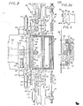
- the machine 1 comprises a frame generally indicated by 10 carrying at the rear a coil 11 on which is wound a strip 12 for example of canvas paper; the reel 11 with the associated strip is rotatably mounted on a frame 13 carrying guide and return rollers 14 to 18 so that the strip 12 is presented at the rear end of the frame 10 of the machine and in the upper part of that -this.
- the strip 12 is progressively formed in a U along its longitudinal axis, by means of a profiled element 20 associated with the frame, which profiled element extends generally from the roll 18 to two lateral rollers 21, 22, with axes vertical, capable of pressing over their entire height, the lateral sides of the strip thus formed in a U against the vertical walls of the above-mentioned profiled element.
- a block 26 suspended from the frame 10 by attachment means 27 themselves slidingly mounted in a support 28 secured to the frame 10 is arranged to receive a jack 30, the piston rod of which is equipped with a generally rectangular base 31 of which the front wall 31A is connected by channels 31B and pipe 31C to suction means not shown.
- the dimensions of this base both in height and in width correspond substantially to the U-shaped profile of the strip; the bed 31 being coupled to the jack 30, it is therefore movable longitudinally between an advanced position and a retracted position.
- the amplitude of the movement of the bed base can be adjusted as a function of the length of strip to be pulled by the sliding mounting of the attachment means 27 in the support 28 (FIG. 1).
- the pot of this cylinder includes a prop lengthwise radial 38 (FIG. 3) whose end provided with a roller 39 is engaged in a fork 40 fixed on the rear face of the bed base 31.
- the base 31 has two functions, namely: ensuring the pressing of a fold formed, and simultaneously driving the U-shaped band forward of a length corresponding to the developed .d.'a fold.
- the forward drive of the U-shaped band is obtained by means of side-clamps arranged substantially at the level of the bed base, along the three sides of the U-shaped band.
- Figures 1 and 3 include a frame 45 surrounding the U-shaped band; this frame is fixed by one side to the upper edge of the box spring 31 and is therefore movable therewith, the three other sides of the frame each carry a pressing device constituted by a strip 46, arranged opposite the sides of the bed base, this strip being itself coupled to a small jack 47 fixed to the frame.
- the frame 10 carries laterally on the three sides of the strip folded in a U, folding units indicated generally at 50 capable of forming an accordion fold in the length of the drawn strip, and retaining units able to hold the formed bundle indicated as a whole at 51.
- the three folding units 50 thus arranged to form a fold of the bellows being similar in their construction and only one will be described in the following.
- Each folding unit 50 comprises a first carriage 52 mounted movable perpendicular to the axis of the strip folded in a U on a fixed slide 53 and this, using a said cylinder 54 to which the first carriage / is coupled.
- Substantially in the middle the axis 58 receives a pinion 70 capable of cooperating with a rack 71 which can be driven in translation by means of a jack 72 which is associated with it.
- each folding unit 50 capable of forming the folds of the bellows comprises two axis, pinion, and crankpin assemblies as described above, driven by a single rack.
- the folding blade 66 fixed to each folding unit has a terminal edge 66A, parallel to said sides of the strip formed in a U shape.
- the folding unit arranged opposite the base of the U formed by the strip comprises a folding blade which extends at least over the entire length of this base, while the associated folding blades the folding units arranged opposite the sides of the U are slightly shorter than these sides; they are arranged in such a way that their respective lower ends are at some distance from the base of the U. Such an arrangement is necessary to allow the simultaneous formation of a fold of the bellows on the three sides of the U-shaped strip.
- retaining units 51 are, like the folding units suitable for forming a fold, arranged in the immediate vicinity of the sides of the strip formed in a U shape; these restraint units all having a similar construction, only one will be described below.
- a restraint unit includes a lever in the shape of a stirrup 75 facing one side of the strip, this stirrup is pivotally mounted on a pin 76 fixed to the end of the slide 53 and extends on either side of this axis being, at one front end, connected to a return spring 77 associated with a tension adjustment device 78 secured to the fixed slide 53, and at the other end equipped with a retaining head indicated as a whole par 79, The end face of this retaining head (FIG.
- FIG. 1 Another complementary retaining unit generally indicated at 90 in FIG. 1 is provided to cooperate with the upper edge of the last partition installed; this retaining unit is carried by a cross member 91 secured to the frame, and it comprises a jack 92 whose pot is pivotally mounted on a bracket 93 formed at the upper end of a vertical arm 94 fixed to the cross member, while the piston rod 95 of this jack is coupled to a lever 96, mounted by a pivoting end on the aforementioned vertical arm, the other end of this lever 96 comprising at least one claw 98.
- this retaining unit is carried by a cross member 91 secured to the frame, and it comprises a jack 92 whose pot is pivotally mounted on a bracket 93 formed at the upper end of a vertical arm 94 fixed to the cross member, while the piston rod 95 of this jack is coupled to a lever 96, mounted by a pivoting end on the aforementioned vertical arm, the other end of this lever 96 comprising at least one claw 98.
- the aforementioned claw 98 as well as the claws 81 fixed to the retaining units 51 may each be in one piece extending over the greater part of the sides of the U, and of the upper edge of a partition, but they can be made up of several elements attached to the end of levers 75 and 96.
- a partition supply device indicated as a whole by 99 is carried by the frame 10
- This device (FIG. 1) comprises a plate 100 extended forwards by an arm 101, carrying a roller 102, able to cooperate with a ramp 103 arranged in an arm 104 extending vertically.
- the plate 100 is coupled by axis 107 to the piston rod of a jack 108 itself carried by a cross member 109 fixed to cheeks 110 fixed to the frame.
- the face of the plate 100 intended to carry a partition 113 is connected by pipeline 112 to a source of vacuum (not shown here); this tray is suitable for transferring a partition 113 from a substantially horizontal position where said partition is disposed on the tray at a substantially vertical position situated at the rear of the developed length of a fold to be formed, as will be seen further.
- the partition 113 has on three sides tongues 114 folded and glued, and it is arranged on the plate 100 so that said tongues are in the case considered -after the formation of a fold facing the rear face of the fold formed, as is clearly visible in particular in Figures 10 to 13, the tabs being cut so that they follow the vertical sides as well as the horizontal bottom side of the fold.
- the frame 10 carries two pressing rollers 115, 116 (FIGS. 1 and 2) mounted to rotate around vertical axes, they are adjustable in spacing and adapted to effect a braking effect on the vertical sides of the bundle indicated as a whole by which it rests on a support table 118.
- the machine is completed by means of retaining the bundle L generally indicated at 120, these means being also adapted to allow the cutting of the bundle in order to constitute a bellows filing cabinet with a chosen plurality of pockets.
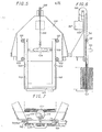
- the retaining and cutting means include essentially ( Figures 5 to 7) a frame 130 mounted vertically movable by its uprights between two pairs of guide rollers 131,132, rotating on a frame 1-33 fixed to the frame.
- the frame has on its front face an operating handle 134, and it is associated by cable 135 and pulley 136 with a counterweight 137.
- the uprights of the frame 130 have grooves 1.40 able to cooperate with the rollers of guide 131, 13 2 .
- the uprights of the frame 130 include in a median zone recesses 139 from which the grooves 141, 142 extend downward, in parallel with the grooves 140.
- the lower edge of the frame has a groove 143.
- the lower edge of the frame has bevelled front and rear faces 145 in order to facilitate the introduction of the latter between two consecutive partitions, therefore inside a pocket, while the thickness E of this frame (FIG. 7) is capable of ensuring the deployment of a fold of the bellows in order to facilitate the transverse cutting which is carried out manually using a blade guided by the aforementioned grooves 141 to 143 formed in the frame.
- all the retaining units 51 arranged laterally and below the strip 12 formed in a U are in the active position, as is the upper retaining unit 96, so that the last partition 113 is retained by the claws associated with each unit, that is to say on its four sides; it is noted that the aforementioned retaining units are activated by the springs 77 and the tension adjustment devices 78.
- the bed base 31 is in the rear position, the side clamps 46 are in the active position and pinch the strip 12 against the bed base 31, the folding blades 66 of the folding units are in an intermediate position and a length of strip "LB", of length equal to the development of a fold is formed between the last partition 113 and the front face of the bed base 31.
- the supply plate 100 of partitions has been ordered to bring a partition 113A (arrow F2) opposite the front face of the bed base 31, that is to say behind the length of the strip.
- this partition 113A. being pressed against the bed base because the front face 31A of the latter is, by the conduits 31B, 31C connected to a source of vacuum; it is noted that the parallel tongues 114, in the example shown, at the vertical and lower horizontal sides of the U-shaped strip are oriented towards the front.
- the bed base 31 is moved forward (arrow F 3) and, simultaneously, the folding blades associated with the folding units 50 have been moved together by the control of the second associated carriages 65 using the jacks 72; the blades 66 therefore pass from a waiting position to an advanced position towards each of the sides of the strip formed in a U shape, and this, substantially in a median zone of the length "LB".
- the bed base 31 continued its movement towards the before and initiates the pressing operation of the fold just formed in order to glue the tabs on the corresponding faces of the fold, while the first carriages 52 are moved along the arrow F 5 by pressurizing the associated jacks 54 so that the folding blades 66 pass from an advanced position to a retracted position, the jacks 72 associated with the second carriages 65, being meanwhile, - kept under pressure to maintain the folding blades in a position identical to that shown in FIG. 10, for which the cam 83 is engaged in the clearance 80.
- the displacement of the first carriages has the effect, on the one hand, of clearing the folding blades 66 from the hollow of the fold formed, and, on the other hand, bringing the cam 83 into contact with the ramp 82 provided in the retaining units 51 and driving the lever 75 (arrow F6) by pivoting about its axis 76 d 'an active position ( Figures 8 to 11) to a retracted erased position ( Figure 12)
- the lever 96 of the upper retaining unit 90 is also erased by means of the jack 92 so that the four sides of the U-shaped strip are released for the operation of pressing.
- the box spring 31 continuing its movement forwards to an extreme advanced position, performs the pressing of the tongues of the partition 113A on the corresponding rear face of the fold just produced.
- the new length LB ′ is formed at the same time as the formation of the fold because the three sides of the U-shaped strip are driven simultaneously by the advance of the bed base 31 and this, by means of the clamps 46 which make the U-shaped band temporarily secured to the bed base 31 (FIGS. 8 to 12), while at the end of pressing, before the bed base 31 returns back, the side clamps 46 are made inoperative in fact said side clamps are inoperative only during the backward travel of the box spring 31.
- the bundle L capable of forming at least one pocket filing cabinet is guided and slightly braked in its advance by the pressure rollers 115, 116, so that the folds are tightened from the training area up to these pressure rollers, which ensures good bonding of the partitions.
- the frame 10 is advantageously equipped with means for retaining the bundle L produced, these means being able to allow easy cutting of the bundle to constitute a bellows filing cabinet, with a selected plurality of partitions forming storage pockets.
- the frame 130 is normally in the low position and forms a stop at the front end of the bundle L; to cut the frame 130 is reassembled using the handle 134, which makes it possible to release a desired number of folds of the bellows and associated cloions and consequently of pockets.
- Such an operation is carried out manually, and when a selected plurality of pockets is obtained, the frame 130 is lowered by inserting it into a pocket between two consecutive partitions; it will be noted that the two partitions considered are manually moved aside in order to favor the insertion of the frame between them, and the frame is lowered until it abuts on the table.
- the accordion fold concerned is completely stretched and the actual cutting is practiced using a sharp blade which is guided along the grooves 141, 142, 143, so that the fold is cut on its three sides in its median zone given the median location of said grooves in the thickness of the frame.
- the bellows file thus obtained with a selected plurality of pockets resting on a table 121 extending the table 118 is then evacuated, and a new cutting can be carried out, in parallel with the formation of new folds.
Landscapes
- Making Paper Articles (AREA)
- Folding Of Thin Sheet-Like Materials, Special Discharging Devices, And Others (AREA)
- Sheet Holders (AREA)
Applications Claiming Priority (2)
| Application Number | Priority Date | Filing Date | Title |
|---|---|---|---|
| FR8007140 | 1980-03-31 | ||
| FR8007140A FR2479099B1 (fr) | 1980-03-31 | 1980-03-31 | Procede de realisation d'une liasse apte a la formation d'au moins un classeur a soufflet, et machine pour la mise en oeuvre d'un tel procede |
Publications (3)
| Publication Number | Publication Date |
|---|---|
| EP0037343A2 true EP0037343A2 (de) | 1981-10-07 |
| EP0037343A3 EP0037343A3 (en) | 1981-10-28 |
| EP0037343B1 EP0037343B1 (de) | 1984-10-03 |
Family
ID=9240308
Family Applications (1)
| Application Number | Title | Priority Date | Filing Date |
|---|---|---|---|
| EP81400516A Expired EP0037343B1 (de) | 1980-03-31 | 1981-03-31 | Verfahren zum Herstellen eines Stapels, geeignet zum Bilden wenigstens einer ausziehbaren Sammelmappe, und Maschine zum Durchführen des Verfahrens |
Country Status (5)
| Country | Link |
|---|---|
| US (1) | US4425111A (de) |
| EP (1) | EP0037343B1 (de) |
| JP (1) | JPS5953175B2 (de) |
| DE (1) | DE3166406D1 (de) |
| FR (1) | FR2479099B1 (de) |
Families Citing this family (13)
| Publication number | Priority date | Publication date | Assignee | Title |
|---|---|---|---|---|
| JPS58147398A (ja) * | 1982-02-25 | 1983-09-02 | ト−イン工業株式会社 | 伸縮自在フアイル及びその製造法 |
| GB2170299B (en) * | 1985-01-30 | 1988-05-11 | Trw Cam Gears Ltd | Vehicle steering system |
| US5201983A (en) * | 1991-12-10 | 1993-04-13 | Corey Thomas J | Apparatus for fabricating a five-piece expanding pocket |
| US5171202A (en) * | 1992-01-17 | 1992-12-15 | Su Ken J | Automatic machine for making accordion data pockets |
| GB2269783A (en) * | 1992-08-18 | 1994-02-23 | Leu Jiann Horng | Expanding plastic file bag with integral base and side portions. |
| DE4413008A1 (de) * | 1994-04-15 | 1995-10-19 | Bielomatik Leuze & Co | Faltvorrichtung für Blattlagen |
| DE9412210U1 (de) * | 1994-07-28 | 1994-12-01 | Schäfer, Hermann, 35116 Hatzfeld | Faltvorrichtung |
| US5745922A (en) * | 1995-01-31 | 1998-05-05 | Kimberly Clark Corporation | Disposable garment and related manufacturing equipment and methods |
| JPH09300491A (ja) * | 1996-05-16 | 1997-11-25 | Hitachi Zosen Corp | シートの折り曲げ整形方法及びシートの折り曲げ整形装置 |
| JPH10236534A (ja) | 1997-02-28 | 1998-09-08 | Hitachi Zosen Corp | 包装用緩衝材 |
| JPH10273174A (ja) | 1997-03-28 | 1998-10-13 | Hitachi Zosen Corp | 包装用緩衝材 |
| US6040753A (en) * | 1999-04-06 | 2000-03-21 | Lockheed Martin Corp. | Ultra-low-profile tube-type magnetics |
| US9266297B1 (en) * | 2011-07-20 | 2016-02-23 | Maxco Supply, Inc. | Pleat forming apparatuses and/or equipment and related methods |
Family Cites Families (4)
| Publication number | Priority date | Publication date | Assignee | Title |
|---|---|---|---|---|
| US1968165A (en) | 1930-03-17 | 1934-07-31 | Quality Park Envelope Co | Method of making expanding wallets, files, and portfolios |
| US2677993A (en) | 1949-06-28 | 1954-05-11 | Magnus Harmonica Corp | Method and apparatus for pleating blanks of laminated sheet material and preformed blanks of laminated sheet material |
| US2696768A (en) | 1949-09-12 | 1954-12-14 | Gen Motors Corp | Bellows folding machine |
| US3434400A (en) | 1967-05-11 | 1969-03-25 | American Fiber Velope Mfg Co | Apparatus for bending accordion pleated strips |
-
1980
- 1980-03-31 FR FR8007140A patent/FR2479099B1/fr not_active Expired
-
1981
- 1981-03-17 US US06/244,726 patent/US4425111A/en not_active Expired - Fee Related
- 1981-03-30 JP JP56047126A patent/JPS5953175B2/ja not_active Expired
- 1981-03-31 EP EP81400516A patent/EP0037343B1/de not_active Expired
- 1981-03-31 DE DE8181400516T patent/DE3166406D1/de not_active Expired
Also Published As
| Publication number | Publication date |
|---|---|
| DE3166406D1 (en) | 1984-11-08 |
| US4425111A (en) | 1984-01-10 |
| EP0037343B1 (de) | 1984-10-03 |
| JPS56151546A (en) | 1981-11-24 |
| FR2479099A1 (fr) | 1981-10-02 |
| EP0037343A3 (en) | 1981-10-28 |
| JPS5953175B2 (ja) | 1984-12-24 |
| FR2479099B1 (fr) | 1986-09-12 |
Similar Documents
| Publication | Publication Date | Title |
|---|---|---|
| EP0037343B1 (de) | Verfahren zum Herstellen eines Stapels, geeignet zum Bilden wenigstens einer ausziehbaren Sammelmappe, und Maschine zum Durchführen des Verfahrens | |
| EP3363553B1 (de) | Blechrollbiegemaschine und rollbiegeverfahren eines blechs mithilfe einer solchen rollbiegemaschine | |
| CH667233A5 (fr) | Installation de decoupage aux filets. | |
| EP2112106B1 (de) | Verfahren und Vorrichtung zum Stoßschneiden und -verkleben für Rundschälmaschine | |
| EP0229554B1 (de) | Vorrichtung zur Befestigung von Verbindungselementen an einem Förderband oder dergleichen | |
| FR2484979A1 (fr) | Procede et appareil d'assemblage de matiere en feuille, notamment pour alimenter en continu des imprimantes rapides | |
| FR2765191A1 (fr) | Procede et machine de collage automatique d'un film plastique thermoretractable sur le fond d'une caisse ouverte | |
| EP3526024B1 (de) | Verfahren und vorrichtung zum formen eines rohlings um eine spindel | |
| FR2597290A1 (fr) | Procede et appareil de fabrication de faisceaux de conducteurs | |
| FR2646398A1 (fr) | Perfectionnements apportes a une machine autorisant la mise en forme de plateaux d'emballage pour le conditionnement et l'expedition de fruits et/ou legumes | |
| BE1009146A3 (fr) | Dispositif servant a coller des renforts lamellaires au fond des caisses en carton. | |
| FR2515484A1 (fr) | Procede et appareil a enrouler des plaques de pate | |
| EP2730527B1 (de) | Abwickelvorrichtung mit einer Bandanhebevorrichtung | |
| FR2550513A1 (fr) | Dispositif de transfert pour une machine a envelopper | |
| FR2860220A1 (fr) | Methode et dispositif pour le prelevement de piles d'ebauches | |
| EP0672479A1 (de) | Stanzvorrichtung metallischer Profile | |
| EP0448444A1 (de) | Falt- und Leimmaschine für vorgeschnittene Zuschnitte, die sich für die Herstellung von Schachteln verschiedener Ausmasse anpassen lassen | |
| FR2464190A1 (fr) | Dispositif d'obturation de recipients au moyen d'un couvercle en un materiau en feuille plastiquement deformable | |
| CA2196699A1 (fr) | Dispositif et procede pour la realisation d'une caisse a partir d'un flan | |
| BE1011594A3 (fr) | Procede de decoupage d'affiches et dispositif pour sa mise en oeuvre. | |
| EP0010528B1 (de) | Vorrichtung zum Vereinzeln und Zuführen V-förmiger Metallschienen | |
| EP1193200A1 (de) | Vorrichtung zum Spleissen von Rollen mit dünnen Bahnen | |
| FR2515573A1 (fr) | Dispositif pour ouvrir les extremites de feuilles en gaine afin de former les carres de fond de sacs a fond croises | |
| FR2613340A1 (fr) | Dispositif de manutention et de montage sur une machine, de bobines de materiaux en bandes | |
| FR2635752A1 (fr) | Machine pour echancrer des flans en carton et installation, equipee d'une telle machine, pour la production de caisses d'emballage |
Legal Events
| Date | Code | Title | Description |
|---|---|---|---|
| PUAI | Public reference made under article 153(3) epc to a published international application that has entered the european phase |
Free format text: ORIGINAL CODE: 0009012 |
|
| PUAL | Search report despatched |
Free format text: ORIGINAL CODE: 0009013 |
|
| AK | Designated contracting states |
Designated state(s): BE DE GB IT NL SE |
|
| AK | Designated contracting states |
Designated state(s): BE DE GB IT NL SE |
|
| 17P | Request for examination filed |
Effective date: 19811222 |
|
| RAP1 | Party data changed (applicant data changed or rights of an application transferred) |
Owner name: CHAZELAS, GILLES REPRESENTE PAR MME DEROUETTEAU-C Owner name: CHAZELAS, DANIEL Owner name: CHAZELAS, CARMEL |
|
| ITF | It: translation for a ep patent filed | ||
| GRAA | (expected) grant |
Free format text: ORIGINAL CODE: 0009210 |
|
| AK | Designated contracting states |
Designated state(s): BE DE GB IT NL SE |
|
| REF | Corresponds to: |
Ref document number: 3166406 Country of ref document: DE Date of ref document: 19841108 |
|
| PLBE | No opposition filed within time limit |
Free format text: ORIGINAL CODE: 0009261 |
|
| STAA | Information on the status of an ep patent application or granted ep patent |
Free format text: STATUS: NO OPPOSITION FILED WITHIN TIME LIMIT |
|
| 26N | No opposition filed | ||
| ITTA | It: last paid annual fee | ||
| PGFP | Annual fee paid to national office [announced via postgrant information from national office to epo] |
Ref country code: BE Payment date: 19920128 Year of fee payment: 12 |
|
| PGFP | Annual fee paid to national office [announced via postgrant information from national office to epo] |
Ref country code: SE Payment date: 19920212 Year of fee payment: 12 |
|
| PGFP | Annual fee paid to national office [announced via postgrant information from national office to epo] |
Ref country code: DE Payment date: 19920305 Year of fee payment: 12 |
|
| PGFP | Annual fee paid to national office [announced via postgrant information from national office to epo] |
Ref country code: GB Payment date: 19920330 Year of fee payment: 12 |
|
| PGFP | Annual fee paid to national office [announced via postgrant information from national office to epo] |
Ref country code: NL Payment date: 19920331 Year of fee payment: 12 |
|
| PG25 | Lapsed in a contracting state [announced via postgrant information from national office to epo] |
Ref country code: GB Effective date: 19930331 Ref country code: BE Effective date: 19930331 |
|
| PG25 | Lapsed in a contracting state [announced via postgrant information from national office to epo] |
Ref country code: SE Effective date: 19930401 |
|
| BERE | Be: lapsed |
Owner name: CHAZELAS GILLES REPRESENTE PAR MME DEROUETTEAU-CH Effective date: 19930331 Owner name: CHAZELAS DANIEL Effective date: 19930331 Owner name: CHAZELAS MARIE DU CARMEL Effective date: 19930331 |
|
| PG25 | Lapsed in a contracting state [announced via postgrant information from national office to epo] |
Ref country code: NL Effective date: 19931001 |
|
| NLV4 | Nl: lapsed or anulled due to non-payment of the annual fee | ||
| GBPC | Gb: european patent ceased through non-payment of renewal fee |
Effective date: 19930331 |
|
| PG25 | Lapsed in a contracting state [announced via postgrant information from national office to epo] |
Ref country code: DE Effective date: 19931201 |
|
| EUG | Se: european patent has lapsed |
Ref document number: 81400516.1 Effective date: 19931110 |