EP0037391A2 - Strombrückenanordnung für eine nach der Doppelpunktschweissmethode arbeitende Schweissmaschine, insbesondere Gitterschweissmaschine - Google Patents
Strombrückenanordnung für eine nach der Doppelpunktschweissmethode arbeitende Schweissmaschine, insbesondere Gitterschweissmaschine Download PDFInfo
- Publication number
- EP0037391A2 EP0037391A2 EP81890053A EP81890053A EP0037391A2 EP 0037391 A2 EP0037391 A2 EP 0037391A2 EP 81890053 A EP81890053 A EP 81890053A EP 81890053 A EP81890053 A EP 81890053A EP 0037391 A2 EP0037391 A2 EP 0037391A2
- Authority
- EP
- European Patent Office
- Prior art keywords
- welding
- pressure
- current bridge
- plane
- double
- Prior art date
- Legal status (The legal status is an assumption and is not a legal conclusion. Google has not performed a legal analysis and makes no representation as to the accuracy of the status listed.)
- Granted
Links
- 238000003466 welding Methods 0.000 title claims abstract description 52
- 238000000034 method Methods 0.000 claims description 2
- 230000007547 defect Effects 0.000 description 1
- 238000006073 displacement reaction Methods 0.000 description 1
- 238000009413 insulation Methods 0.000 description 1
- 238000004519 manufacturing process Methods 0.000 description 1
Images

Classifications
-
- B—PERFORMING OPERATIONS; TRANSPORTING
- B23—MACHINE TOOLS; METAL-WORKING NOT OTHERWISE PROVIDED FOR
- B23K—SOLDERING OR UNSOLDERING; WELDING; CLADDING OR PLATING BY SOLDERING OR WELDING; CUTTING BY APPLYING HEAT LOCALLY, e.g. FLAME CUTTING; WORKING BY LASER BEAM
- B23K11/00—Resistance welding; Severing by resistance heating
- B23K11/002—Resistance welding; Severing by resistance heating specially adapted for particular articles or work
- B23K11/008—Manufacturing of metallic grids or mats by spot welding
-
- B—PERFORMING OPERATIONS; TRANSPORTING
- B21—MECHANICAL METAL-WORKING WITHOUT ESSENTIALLY REMOVING MATERIAL; PUNCHING METAL
- B21F—WORKING OR PROCESSING OF METAL WIRE
- B21F27/00—Making wire network, i.e. wire nets
- B21F27/08—Making wire network, i.e. wire nets with additional connecting elements or material at crossings
- B21F27/10—Making wire network, i.e. wire nets with additional connecting elements or material at crossings with soldered or welded crossings
Definitions
- the invention relates to a current bridge arrangement for a welding machine working in accordance with the double-spot welding method, in particular a lattice welding machine, with at least one pair of active electrodes arranged offset in relation to one another in the direction of the double-spot welding path and connected to the secondary side of a welding transformer Current bridge passive counter electrodes are assigned.
- a current bridge arrangement of this type intended for grid welding machines is known from AT-PS 259.993.
- the bearing point of the current bridge on a plunger moving it in the direction perpendicular to the welding plane and the two points of contact of the upper passive counterelectrodes arranged on the current bridge form a rigid triangle with one of the grid wires to be welded.
- the known current bridge especially in the case of very closely adjacent welding points, i.e. in the case of grids with very small mutual wire spacings, cannot be set so that the same welding pressure is always applied to both welding points even when the wire diameter fluctuates, because this would usually require a lateral shift of the articulation point of the current bridge to the plunger.
- a pressure beam carrying the current bridge is provided, the end parts of which protrude into the welding plane and are slidably guided in guides running normal to the welding plane and pivotable in the beam plane, and in that at the end parts of the pressure beam at the level of the welding plane the lower ends of two pressure members are articulated, the upper ends of which are articulated at the ends of a centrally pivotably mounted second bar which is axially parallel to the connecting line of the articulation points of the lower ends of the pressure members on the pressure bar.
- the pressure bar carrying the current bridge with the passive counter electrodes, the two pressure members articulated to the pressure bar end parts and the articulated second bar connected together form a four-bar linkage which enables such a free adjustment of the pressure bar and thus the current bridge with respect to the Welding level enables the welding pressures acting on the two passive counter electrodes to be automatically adjusted to one another.
- hydraulically or pneumatically actuated working cylinders are provided as pressure members and the second bar is pivotally but immovably supported in its center.
- push rods are provided as pressure members
- the second bar can be pivoted in its center and is displaceable in the direction perpendicular to the welding plane, and a working cylinder acts on the bearing point of the second bar.
- busbars 1 and 2 can be seen, which extend in the direction of the double-spot welding section and are electrically separated from each other by an insulation, not shown.
- Two active electrodes 3, 4 are adjustable and lockable on these busbars.
- a current bridge 7 can be seen, which has the shape of a current rail, along which passive counter electrodes 8 and 9 are arranged to be adjustable and ascertainable.
- the active electrodes 3 and 4 can be adjusted along the associated, mutually insulated busbars 1 and 2 according to a desired longitudinal wire pitch; the passive counter-electrodes 8 and 9 are set on the common busbar or current bridge 7 so that they are each opposite an active electrode.
- a small longitudinal wire pitch i.e. a small mutual electrode spacing
- the defect already explained in the known current bridge arrangements, which is to be remedied by the invention arises that the welding pressures which are transmitted from the current bridge to the two counter electrodes of a double-spot welding path are due to a lack of free
- the adjustability of the current bridge is generally not the same.
- the current bridge 7 is arranged on a pressure beam 15, the ends 15a, 15b of which protrude obliquely downwards into the welding plane S and are slidably guided in guides 16, 17 which run normal to this plane.
- a space e is provided between the outer, vertical boundary of the guides 16, 17 and the beam ends parallel to this boundary, so that pivoting of the beam 15 in the beam plane is possible.
- the lower ends 18, 19 are articulated by two pressure members 26, 27 on the beam ends 15a, 15b.
- guide rollers can be provided at these articulation points, which roll on the front and rear boundaries of the guides 16, 17, so that the beam 15 is always exactly centered with respect to the center plane of the machine.
- the upper ends 20, 21 of the pressure members 26, 27 are hinged to the ends of a second beam 24.
- the axis of the second beam 24 runs parallel to the connecting line of the articulation points 18, 19 of the pressure members 26, 27 on the electrode beam 15 and thus also parallel to the welding plane S.
- the beam 24 is pivotable in a joint 25 and in the example shown is immovably mounted.
- hydraulically or pneumatically actuated working cylinders are provided as pressure members 26, 27.
- adjustable return springs 28 can also be provided.
- the pressure members 26, 27 can also be designed as simple push rods, in which case the joint 25 must be designed to be displaceable in the direction of the plane of symmetry of the machine.
- the joint 25 For the displacement of this joint is a rigidly attached at one end in the machine frame Working cylinder 29 is provided, the piston rod engages on the joint 25 guided parallel to the machine center plane.
Landscapes
- Engineering & Computer Science (AREA)
- Mechanical Engineering (AREA)
- Manufacturing & Machinery (AREA)
- Resistance Welding (AREA)
- Arc Welding In General (AREA)
Abstract
Description
- Die Erfindung betrifft eine Strombrückenanordnung für eine nach der Doppelpunktschweißmethode arbeitende Schweißmaschine, insbesondere Gitterschweißmaschine, mit zumindest einem Paar von in Richtung der Doppelpunktschweißstrecke gegeneinander versetzt angeordneten, an die Sekundärseite eines Schweißtransformators angeschlossenen aktiven Elektroden, denen jenseits der Schweißebene auf einer schwenkbar gelagerten und den Schweißdruck aufbringenden Strombrücke passive Gegenelektroden zugeordnet sind.
- Eine für Gitterschweißmaschinen bestimmte Strombrückenanordnung dieser Gattung ist aus der AT-PS 259.993 bekannt. Bei der bekannten Strombrückenanordnung bilden der Lagerpunkt der Strombrücke an einem diese in Richtung senkrecht zur Schweißebene bewegenden Stößel und die beiden Berührungspunkte der oberen, an der Strombrücke angeordneten passiven Gegenelektroden mit dem einen der zu verschweißenden Gitterdrähte ein in sich starres Dreieck. Zufolge dieser Ausbildung kann sich die bekannte Strombrücke, insbesondere bei sehr eng benachbart liegenden Schweißpunkten, also bei Gittern mit sehr kleinen gegenseitigen Drahtabständen, nicht in freiem Spiel so einstellen, daß auf beide Schweißpunkte auch bei Schwankungen der Drahtdurchmesser stets der gleiche Schweißdruck aufgebracht wird, weil dies in der Regel eine seitliche Verschiebung des Anlenkpunktes der Strombrücke an den Stößel erfordern würde. Ähnliche Verhältnisse liegen bei einer aus der AT-PS 298.204 bekannten Strombrückenanordnung der einleitend angegebenen Gattung vor, bei welcher jede Strombrücke in zwei nahe ihren Enden liegenden Punkten durch Gelenke mit federbelasteten Andrückstangen verbunden ist, von denen jede nahe ihrem einen Ende einen Anschlagteil trägt, der selbstzentrierend mit einem als Gegenanschlag dienenden Sitz zusammenwirkt, während das andere Ende jeder Andrückstange mit radialem Spiel längsgeführt ist. Im Falle einer Doppelpunktschweißung ungleich dicker Drähte stellt sich hiebei die Strombrücke schräg und die Folge davon sind ungleich verteilte Schweißdrücke und daher auch ungleichmäßige Schweißungen.
- Hier setzt die Erfindung ein. Sie soll die Aufgabe lösen, bei Schwankungen des Drahtdurchmessers unabhängig vom Abstand der Schweißpunkte in allen Fällen gleiche Elektrodendrücke und damit gleichmäßige Schweißungen sicherzustellen.
- Diese Aufgabe wird erfindungsgemäß dadurch gelöst, daß ein die Strombrücke tragender Druckbalken vorgesehen ist, dessen Endteile bis in die Schweißebene auskragen und in normal zur Schweißebene verlaufenden Führungen gleitend und in der Balkenebene verschwenkbar geführt sind, und daß an den Endteilen des Druckbalkens in Höhe der Schweißebene die unteren Enden zweier Druckglieder angelenkt sind, deren obere Enden an den Enden eines mittig schwenkbar gelagerten, zur Verbindungslinie der Anlenkpunkte der unteren Enden der Druckglieder am Druckbalken achsparallelen zweiten Balkens angelenkt sind.
- Auf diese Weise wird erreicht, daß der die Strombrücke mit den passiven Gegenelektroden tragende Druckbalken, die beiden an die Druckbalkenendteile angelenkten Druckglieder und der gelenkig mit diesen verbundene zweite Balken zusammen ein Gelenkviereck bilden, das eine derart freie Verstellung des Druckbalkens und damit der Strombrücke bezüglich der Schweißebene ermöglicht, daß die auf die beiden passiven Gegenelektroden wirkenden Schweißdrücke automatisch aneinander angeglichen werden.
- Bei einer speziellen Ausführungsform der Erfindung sind als Druckglieder hydraulisch oder pneumatisch betätigbare Arbeitszylinder vorgesehen und der zweite Balken ist in seiner Mitte in einem Gelenk schwenkbar, aber unverschiebbar gelagert.
- Bei einer anderen Ausführungsform sind als Druckglieder Schubstangen vorgesehen, der zweite Balken ist in seiner Mitte schwenkbar und in Richtung senkrecht zur Schweißebene verschiebbar gelagert und am Lagerpunkt des zweiten Balkens greift ein Arbeitszylinder an.
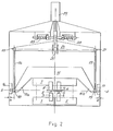
- Diese beiden Ausführungsbeispiele der Erfindung sind in den Figuren 1 bzw. 2 der Zeichnung jeweils in Seitenansicht dargestellt und werden nachfolgend genauer beschrieben.
- In Figur 1 sind zwei Stromschienen 1 und 2 erkennbar, welche sich in Richtung der Doppelpunktschweißstrecke erstrecken und durch eine nicht dargestellte Isolierung elektrisch voneinander getrennt sind. Auf diesen Stromschienen sind zwei aktive Elektroden 3, 4 verstellbar und feststellbar angeordnet. Jenseits der durch zwei Längsstäbe 5 und einen Querstab 6 definierten Gitterherstellungs-oder Schweißebene S ist eine Strombrücke 7 erkennbar, welche die Form einer Stromschiene hat, längs welcher passive Gegenelektroden 8 und 9 verstellbar und feststellbar angeordnet sind.
- Die aktiven Elektroden 3 und 4 können längs der ihnen zugeordneten, voneinander isolierten Stromschienen 1 und 2 entsprechend einer gewünschten Längsdrahtteilung eingestellt werden; die passiven Gegenelektroden 8 und 9 werden auf der gemeinsamen Stromschiene oder Strombrücke 7 so eingestellt, daß sie je einer aktiven Elektrode gegenüberliegen. Insbesondere bei Einstellung einer kleinen Längsdrahtteilung, also eines kleinen gegenseitigen Elektrodenabstandes, ergibt sich bei den bekannten Strombrückenanordnungen der bereits erläuterte , durch die Erfindung zu behebende Mangel, daß die Schweißdrücke, die von der Strombrücke auf die beiden Gegenelektroden einer Doppelpunktschweißstrecke übertragen werden, infolge mangelnder freier Verstellbarkeit der Strombrücke im allgemeinen ungleich groß sind.
- Erfindungsgemäß ist die Strombrücke 7 auf einem Druckbalken 15 angeordnet, dessen Enden 15a, 15b schräg nach unten bis in die Schweißebene S auskragen und in normal zu dieser Ebene verlaufenden Führungen 16, 17 gleitend geführt sind.
- Wie aus Figur 1 erkennbar ist, ist zwischen der äußeren, senkrechten Begrenzung der Führungen 16, 17 und den zu dieser Begrenzung parallelen Balkenenden ein Zwischenraum e vorgesehen, so daß ein Verschwenken des Balkens 15 in der Balkenebene möglich ist.
- In Höhe der Schweißebene S sind an den Balkenenden 15a, 15b die unteren Enden 18, 19 von zwei Druckgliedern 26, 27 angelenkt. Zweckmäßig können an diesen Anlenkpunkten Führungsrollen vorgesehen werden, welche an den vorderen und hinteren Begrenzungen der Führungen 16, 17 abrollen, so daß der Balken 15 gegenüber der Mittelebene der Maschine stets exakt zentriert wird. Die oberen Enden 20, 21 der Druckglieder 26, 27 sind an den Enden eines zweiten Balkens 24 angelenkt. Die Achse des zweiten Balkens 24 verläuft parallel zur Verbindungslinie der Anlenkpunkte 18, 19 der Druckglieder 26, 27 am Elektrodenbalken 15 und damit auch parallel zur Schweißebene S. Der Balken 24 ist in einem Gelenk 25 schwenkbar und im dargestellten Beispiel unverschieblich gelagert. In der dargestellten Ausführungsform sind als Druckglieder 26, 27 hydraulisch oder pneumatisch betätigbare Arbeitszylinder vorgesehen.
- Um die gesamte Schweißeinrichtung im Ruhezustand stets in einer vorgegebenen Ruhelage zu halten, können noch einstellbare Rückstellfedern 28 vorgesehen sein.
- Gemäß Figur 2 können die Druckglieder 26, 27 auch als einfache Druckstangen ausgebildet sein, wobei dann das Gelenk 25 in Richtung der Symmetrieebene der Maschine verschiebbar ausgebildet werden muß. Für die Verschiebung dieses Gelenkes ist ein an einem Ende starr im Maschinengestell befestigter Arbeitszylinder 29 vorgesehen, dessen Kolbenstange an dem parallel zur Maschinenmittelebene geführten Gelenk 25 angreift.
Claims (4)
Applications Claiming Priority (2)
| Application Number | Priority Date | Filing Date | Title |
|---|---|---|---|
| AT1735/80 | 1980-03-31 | ||
| AT173580A AT368046B (de) | 1980-03-31 | 1980-03-31 | Strombrueckenanordnung fuer eine nach der doppelpunktschweissmethode arbeitende schweissmaschine, insbesondere gitterschweissmaschine |
Publications (3)
| Publication Number | Publication Date |
|---|---|
| EP0037391A2 true EP0037391A2 (de) | 1981-10-07 |
| EP0037391A3 EP0037391A3 (en) | 1982-02-24 |
| EP0037391B1 EP0037391B1 (de) | 1984-03-21 |
Family
ID=3519867
Family Applications (1)
| Application Number | Title | Priority Date | Filing Date |
|---|---|---|---|
| EP19810890053 Expired EP0037391B1 (de) | 1980-03-31 | 1981-03-30 | Strombrückenanordnung für eine nach der Doppelpunktschweissmethode arbeitende Schweissmaschine, insbesondere Gitterschweissmaschine |
Country Status (5)
| Country | Link |
|---|---|
| EP (1) | EP0037391B1 (de) |
| AT (1) | AT368046B (de) |
| DE (1) | DE3162732D1 (de) |
| PL (1) | PL137481B1 (de) |
| SU (1) | SU1074391A3 (de) |
Cited By (2)
| Publication number | Priority date | Publication date | Assignee | Title |
|---|---|---|---|---|
| EP2841229B1 (de) * | 2012-04-28 | 2022-06-22 | Volkswagen Aktiengesellschaft | FÜGEN VON BAUTEILEN MITTELS EINES WIDERSTANDSSCHWEIßENS |
| CN115213596A (zh) * | 2022-07-29 | 2022-10-21 | 中车大连机车车辆有限公司 | 城铁车辆主横梁点焊限位装置 |
Family Cites Families (6)
| Publication number | Priority date | Publication date | Assignee | Title |
|---|---|---|---|---|
| DD88238A (de) * | ||||
| DE1107856B (de) * | 1959-06-04 | 1961-05-31 | Emil Jaeger K G | Einrichtung zur Einstellung des Schweissdruckes bei Drahtnetzschweissmaschinen |
| DE1176299B (de) * | 1961-11-08 | 1964-08-20 | Schlatter Ag | Gitterschweissmaschine |
| AT259993B (de) * | 1962-06-18 | 1968-02-12 | Avi Alpenlaendische Vered | Doppelpunkt-Gitterschweißmaschine |
| US3194935A (en) * | 1962-10-29 | 1965-07-13 | United States Steel Corp | Method and apparatus for manufacturing hinged panels of wire fabric |
| AT298204B (de) * | 1970-03-25 | 1972-04-25 | Evg Entwicklung Verwert Ges | Halterung für die Strombrücken von nach der Doppelpunktmethode arbeitenden Schweißmaschinen an einem Elektrodenbalken, insbesondere für Gitterschweißmaschinen |
-
1980
- 1980-03-31 AT AT173580A patent/AT368046B/de not_active IP Right Cessation
-
1981
- 1981-03-09 SU SU813255247A patent/SU1074391A3/ru active
- 1981-03-18 PL PL23021081A patent/PL137481B1/pl unknown
- 1981-03-30 EP EP19810890053 patent/EP0037391B1/de not_active Expired
- 1981-03-30 DE DE8181890053T patent/DE3162732D1/de not_active Expired
Cited By (2)
| Publication number | Priority date | Publication date | Assignee | Title |
|---|---|---|---|---|
| EP2841229B1 (de) * | 2012-04-28 | 2022-06-22 | Volkswagen Aktiengesellschaft | FÜGEN VON BAUTEILEN MITTELS EINES WIDERSTANDSSCHWEIßENS |
| CN115213596A (zh) * | 2022-07-29 | 2022-10-21 | 中车大连机车车辆有限公司 | 城铁车辆主横梁点焊限位装置 |
Also Published As
| Publication number | Publication date |
|---|---|
| ATA173580A (de) | 1982-01-15 |
| PL137481B1 (en) | 1986-06-30 |
| EP0037391A3 (en) | 1982-02-24 |
| PL230210A1 (de) | 1981-10-30 |
| EP0037391B1 (de) | 1984-03-21 |
| DE3162732D1 (en) | 1984-04-26 |
| SU1074391A3 (ru) | 1984-02-15 |
| AT368046B (de) | 1982-08-25 |
Similar Documents
| Publication | Publication Date | Title |
|---|---|---|
| DE2704540C2 (de) | ||
| EP0453933B1 (de) | Vorrichtung zum Schneiden von gestapeltem, blattförmigem Gut | |
| DE3873867T2 (de) | Vorrichtung zur herstellung von gebaeudeplatten. | |
| CH621502A5 (de) | ||
| DE2943974C2 (de) | Pressenpartie einer Papiermaschine | |
| DE2801249C2 (de) | Entgratungsvorrichtung in einer auf einem zu entgratenden Schienenstrang geführten Stumpfschweißmaschine | |
| DE2601965A1 (de) | Stumpfschweissmaschine | |
| DE3224065C2 (de) | Verstellbare Stranggießkokille für Vielfachstranggießanlagen | |
| EP0831417A2 (de) | Chipkarten-Kontaktiergerät | |
| DE2825301A1 (de) | Vorrichtung zur herstellung eines waermegedaemmten verbundprofils | |
| EP0037391B1 (de) | Strombrückenanordnung für eine nach der Doppelpunktschweissmethode arbeitende Schweissmaschine, insbesondere Gitterschweissmaschine | |
| EP0857522A1 (de) | Walzstrasse | |
| DE3742697C2 (de) | ||
| DE9210167U1 (de) | Vorrichtung zum Brechen von Pleueln | |
| EP0053601A1 (de) | Vorrichtung zum zickzackförmigen Biegen gerader Drähte, insbesondere für Maschinen zum Herstellen von Diagonalgittern | |
| EP0499019A2 (de) | Widerstandsschweissmaschine, insbesondere zum Abbrennstumpfschweissen von Schienen | |
| DE2636220C3 (de) | Vorrichtung zum Positionieren aufeinander folgender Kettenglieder eines Kettenstranges | |
| DE19909283A1 (de) | Verfahren zur Befestigung von Sitzschienen | |
| DE2148528A1 (de) | Auswerfervorrichtung zum ausschieben von pressteilen aus den ortsfesten matrizen von eindruck-, doppeldruck- oder mehrstufenpressen | |
| DE3232969C2 (de) | Auf zwei Führungsschienen geführter Schlitten für Nähmaschinen | |
| DE10236775A1 (de) | Einrichtung zum Absenken von Glasplatten auf Stapelgestelle | |
| DE2543809A1 (de) | Einspannbare schiene | |
| DE2920468A1 (de) | Klemmelement zum loesbaren befestigen von in nuten eines gehaeuses eingeschobenen leiterplatten | |
| DE3042418A1 (de) | Werkzeug zum bearbeiten der anschlussdraehte von elektrischen bauelementen | |
| DE19525135C2 (de) | Dehnungsstoß |
Legal Events
| Date | Code | Title | Description |
|---|---|---|---|
| PUAI | Public reference made under article 153(3) epc to a published international application that has entered the european phase |
Free format text: ORIGINAL CODE: 0009012 |
|
| AK | Designated contracting states |
Designated state(s): BE CH DE FR GB |
|
| PUAL | Search report despatched |
Free format text: ORIGINAL CODE: 0009013 |
|
| AK | Designated contracting states |
Designated state(s): BE CH DE FR GB |
|
| 17P | Request for examination filed |
Effective date: 19820514 |
|
| GRAA | (expected) grant |
Free format text: ORIGINAL CODE: 0009210 |
|
| AK | Designated contracting states |
Designated state(s): BE CH DE FR GB LI |
|
| PGFP | Annual fee paid to national office [announced via postgrant information from national office to epo] |
Ref country code: BE Payment date: 19840331 Year of fee payment: 4 |
|
| PGFP | Annual fee paid to national office [announced via postgrant information from national office to epo] |
Ref country code: FR Payment date: 19840402 Year of fee payment: 4 |
|
| REF | Corresponds to: |
Ref document number: 3162732 Country of ref document: DE Date of ref document: 19840426 |
|
| PGFP | Annual fee paid to national office [announced via postgrant information from national office to epo] |
Ref country code: DE Payment date: 19840523 Year of fee payment: 4 |
|
| ET | Fr: translation filed | ||
| PLBE | No opposition filed within time limit |
Free format text: ORIGINAL CODE: 0009261 |
|
| STAA | Information on the status of an ep patent application or granted ep patent |
Free format text: STATUS: NO OPPOSITION FILED WITHIN TIME LIMIT |
|
| 26N | No opposition filed | ||
| BERE | Be: lapsed |
Owner name: EVG ENTWICKLUNGS- U. VERWERTUNGS -G.M.B.H. Effective date: 19880331 |
|
| PG25 | Lapsed in a contracting state [announced via postgrant information from national office to epo] |
Ref country code: GB Free format text: LAPSE BECAUSE OF NON-PAYMENT OF DUE FEES Effective date: 19881118 |
|
| GBPC | Gb: european patent ceased through non-payment of renewal fee | ||
| PG25 | Lapsed in a contracting state [announced via postgrant information from national office to epo] |
Ref country code: FR Free format text: LAPSE BECAUSE OF NON-PAYMENT OF DUE FEES Effective date: 19881130 |
|
| PG25 | Lapsed in a contracting state [announced via postgrant information from national office to epo] |
Ref country code: DE Effective date: 19881201 |
|
| REG | Reference to a national code |
Ref country code: FR Ref legal event code: ST |
|
| PG25 | Lapsed in a contracting state [announced via postgrant information from national office to epo] |
Ref country code: BE Effective date: 19890331 |
|
| PGFP | Annual fee paid to national office [announced via postgrant information from national office to epo] |
Ref country code: CH Payment date: 19930222 Year of fee payment: 13 |
|
| PG25 | Lapsed in a contracting state [announced via postgrant information from national office to epo] |
Ref country code: LI Effective date: 19940331 Ref country code: CH Effective date: 19940331 |
|
| REG | Reference to a national code |
Ref country code: CH Ref legal event code: PL |