EP0037391A2 - Arrangement de pont de contact pour une machine de soudage par deux points, en particulier pour une machine à souder les treillis - Google Patents
Arrangement de pont de contact pour une machine de soudage par deux points, en particulier pour une machine à souder les treillis Download PDFInfo
- Publication number
- EP0037391A2 EP0037391A2 EP81890053A EP81890053A EP0037391A2 EP 0037391 A2 EP0037391 A2 EP 0037391A2 EP 81890053 A EP81890053 A EP 81890053A EP 81890053 A EP81890053 A EP 81890053A EP 0037391 A2 EP0037391 A2 EP 0037391A2
- Authority
- EP
- European Patent Office
- Prior art keywords
- welding
- pressure
- current bridge
- plane
- double
- Prior art date
- Legal status (The legal status is an assumption and is not a legal conclusion. Google has not performed a legal analysis and makes no representation as to the accuracy of the status listed.)
- Granted
Links
- 238000003466 welding Methods 0.000 title claims abstract description 52
- 238000000034 method Methods 0.000 claims description 2
- 230000007547 defect Effects 0.000 description 1
- 238000006073 displacement reaction Methods 0.000 description 1
- 238000009413 insulation Methods 0.000 description 1
- 238000004519 manufacturing process Methods 0.000 description 1
Images

Classifications
-
- B—PERFORMING OPERATIONS; TRANSPORTING
- B23—MACHINE TOOLS; METAL-WORKING NOT OTHERWISE PROVIDED FOR
- B23K—SOLDERING OR UNSOLDERING; WELDING; CLADDING OR PLATING BY SOLDERING OR WELDING; CUTTING BY APPLYING HEAT LOCALLY, e.g. FLAME CUTTING; WORKING BY LASER BEAM
- B23K11/00—Resistance welding; Severing by resistance heating
- B23K11/002—Resistance welding; Severing by resistance heating specially adapted for particular articles or work
- B23K11/008—Manufacturing of metallic grids or mats by spot welding
-
- B—PERFORMING OPERATIONS; TRANSPORTING
- B21—MECHANICAL METAL-WORKING WITHOUT ESSENTIALLY REMOVING MATERIAL; PUNCHING METAL
- B21F—WORKING OR PROCESSING OF METAL WIRE
- B21F27/00—Making wire network, i.e. wire nets
- B21F27/08—Making wire network, i.e. wire nets with additional connecting elements or material at crossings
- B21F27/10—Making wire network, i.e. wire nets with additional connecting elements or material at crossings with soldered or welded crossings
Definitions
- the invention relates to a current bridge arrangement for a welding machine working in accordance with the double-spot welding method, in particular a lattice welding machine, with at least one pair of active electrodes arranged offset in relation to one another in the direction of the double-spot welding path and connected to the secondary side of a welding transformer Current bridge passive counter electrodes are assigned.
- a current bridge arrangement of this type intended for grid welding machines is known from AT-PS 259.993.
- the bearing point of the current bridge on a plunger moving it in the direction perpendicular to the welding plane and the two points of contact of the upper passive counterelectrodes arranged on the current bridge form a rigid triangle with one of the grid wires to be welded.
- the known current bridge especially in the case of very closely adjacent welding points, i.e. in the case of grids with very small mutual wire spacings, cannot be set so that the same welding pressure is always applied to both welding points even when the wire diameter fluctuates, because this would usually require a lateral shift of the articulation point of the current bridge to the plunger.
- a pressure beam carrying the current bridge is provided, the end parts of which protrude into the welding plane and are slidably guided in guides running normal to the welding plane and pivotable in the beam plane, and in that at the end parts of the pressure beam at the level of the welding plane the lower ends of two pressure members are articulated, the upper ends of which are articulated at the ends of a centrally pivotably mounted second bar which is axially parallel to the connecting line of the articulation points of the lower ends of the pressure members on the pressure bar.
- the pressure bar carrying the current bridge with the passive counter electrodes, the two pressure members articulated to the pressure bar end parts and the articulated second bar connected together form a four-bar linkage which enables such a free adjustment of the pressure bar and thus the current bridge with respect to the Welding level enables the welding pressures acting on the two passive counter electrodes to be automatically adjusted to one another.
- hydraulically or pneumatically actuated working cylinders are provided as pressure members and the second bar is pivotally but immovably supported in its center.
- push rods are provided as pressure members
- the second bar can be pivoted in its center and is displaceable in the direction perpendicular to the welding plane, and a working cylinder acts on the bearing point of the second bar.
- busbars 1 and 2 can be seen, which extend in the direction of the double-spot welding section and are electrically separated from each other by an insulation, not shown.
- Two active electrodes 3, 4 are adjustable and lockable on these busbars.
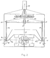
- a current bridge 7 can be seen, which has the shape of a current rail, along which passive counter electrodes 8 and 9 are arranged to be adjustable and ascertainable.
- the active electrodes 3 and 4 can be adjusted along the associated, mutually insulated busbars 1 and 2 according to a desired longitudinal wire pitch; the passive counter-electrodes 8 and 9 are set on the common busbar or current bridge 7 so that they are each opposite an active electrode.
- a small longitudinal wire pitch i.e. a small mutual electrode spacing
- the defect already explained in the known current bridge arrangements, which is to be remedied by the invention arises that the welding pressures which are transmitted from the current bridge to the two counter electrodes of a double-spot welding path are due to a lack of free
- the adjustability of the current bridge is generally not the same.
- the current bridge 7 is arranged on a pressure beam 15, the ends 15a, 15b of which protrude obliquely downwards into the welding plane S and are slidably guided in guides 16, 17 which run normal to this plane.
- a space e is provided between the outer, vertical boundary of the guides 16, 17 and the beam ends parallel to this boundary, so that pivoting of the beam 15 in the beam plane is possible.
- the lower ends 18, 19 are articulated by two pressure members 26, 27 on the beam ends 15a, 15b.
- guide rollers can be provided at these articulation points, which roll on the front and rear boundaries of the guides 16, 17, so that the beam 15 is always exactly centered with respect to the center plane of the machine.
- the upper ends 20, 21 of the pressure members 26, 27 are hinged to the ends of a second beam 24.
- the axis of the second beam 24 runs parallel to the connecting line of the articulation points 18, 19 of the pressure members 26, 27 on the electrode beam 15 and thus also parallel to the welding plane S.
- the beam 24 is pivotable in a joint 25 and in the example shown is immovably mounted.
- hydraulically or pneumatically actuated working cylinders are provided as pressure members 26, 27.
- adjustable return springs 28 can also be provided.
- the pressure members 26, 27 can also be designed as simple push rods, in which case the joint 25 must be designed to be displaceable in the direction of the plane of symmetry of the machine.
- the joint 25 For the displacement of this joint is a rigidly attached at one end in the machine frame Working cylinder 29 is provided, the piston rod engages on the joint 25 guided parallel to the machine center plane.
Landscapes
- Engineering & Computer Science (AREA)
- Mechanical Engineering (AREA)
- Manufacturing & Machinery (AREA)
- Resistance Welding (AREA)
- Arc Welding In General (AREA)
Applications Claiming Priority (2)
| Application Number | Priority Date | Filing Date | Title |
|---|---|---|---|
| AT1735/80 | 1980-03-31 | ||
| AT173580A AT368046B (de) | 1980-03-31 | 1980-03-31 | Strombrueckenanordnung fuer eine nach der doppelpunktschweissmethode arbeitende schweissmaschine, insbesondere gitterschweissmaschine |
Publications (3)
| Publication Number | Publication Date |
|---|---|
| EP0037391A2 true EP0037391A2 (fr) | 1981-10-07 |
| EP0037391A3 EP0037391A3 (en) | 1982-02-24 |
| EP0037391B1 EP0037391B1 (fr) | 1984-03-21 |
Family
ID=3519867
Family Applications (1)
| Application Number | Title | Priority Date | Filing Date |
|---|---|---|---|
| EP19810890053 Expired EP0037391B1 (fr) | 1980-03-31 | 1981-03-30 | Arrangement de pont de contact pour une machine de soudage par deux points, en particulier pour une machine à souder les treillis |
Country Status (5)
| Country | Link |
|---|---|
| EP (1) | EP0037391B1 (fr) |
| AT (1) | AT368046B (fr) |
| DE (1) | DE3162732D1 (fr) |
| PL (1) | PL137481B1 (fr) |
| SU (1) | SU1074391A3 (fr) |
Cited By (2)
| Publication number | Priority date | Publication date | Assignee | Title |
|---|---|---|---|---|
| EP2841229B1 (fr) * | 2012-04-28 | 2022-06-22 | Volkswagen Aktiengesellschaft | Assemblage de pièces par soudage par résistance |
| CN115213596A (zh) * | 2022-07-29 | 2022-10-21 | 中车大连机车车辆有限公司 | 城铁车辆主横梁点焊限位装置 |
Family Cites Families (6)
| Publication number | Priority date | Publication date | Assignee | Title |
|---|---|---|---|---|
| DD88238A (fr) * | ||||
| DE1107856B (de) * | 1959-06-04 | 1961-05-31 | Emil Jaeger K G | Einrichtung zur Einstellung des Schweissdruckes bei Drahtnetzschweissmaschinen |
| DE1176299B (de) * | 1961-11-08 | 1964-08-20 | Schlatter Ag | Gitterschweissmaschine |
| AT259993B (de) * | 1962-06-18 | 1968-02-12 | Avi Alpenlaendische Vered | Doppelpunkt-Gitterschweißmaschine |
| US3194935A (en) * | 1962-10-29 | 1965-07-13 | United States Steel Corp | Method and apparatus for manufacturing hinged panels of wire fabric |
| AT298204B (de) * | 1970-03-25 | 1972-04-25 | Evg Entwicklung Verwert Ges | Halterung für die Strombrücken von nach der Doppelpunktmethode arbeitenden Schweißmaschinen an einem Elektrodenbalken, insbesondere für Gitterschweißmaschinen |
-
1980
- 1980-03-31 AT AT173580A patent/AT368046B/de not_active IP Right Cessation
-
1981
- 1981-03-09 SU SU813255247A patent/SU1074391A3/ru active
- 1981-03-18 PL PL23021081A patent/PL137481B1/pl unknown
- 1981-03-30 EP EP19810890053 patent/EP0037391B1/fr not_active Expired
- 1981-03-30 DE DE8181890053T patent/DE3162732D1/de not_active Expired
Cited By (2)
| Publication number | Priority date | Publication date | Assignee | Title |
|---|---|---|---|---|
| EP2841229B1 (fr) * | 2012-04-28 | 2022-06-22 | Volkswagen Aktiengesellschaft | Assemblage de pièces par soudage par résistance |
| CN115213596A (zh) * | 2022-07-29 | 2022-10-21 | 中车大连机车车辆有限公司 | 城铁车辆主横梁点焊限位装置 |
Also Published As
| Publication number | Publication date |
|---|---|
| ATA173580A (de) | 1982-01-15 |
| PL137481B1 (en) | 1986-06-30 |
| EP0037391A3 (en) | 1982-02-24 |
| PL230210A1 (fr) | 1981-10-30 |
| EP0037391B1 (fr) | 1984-03-21 |
| DE3162732D1 (en) | 1984-04-26 |
| SU1074391A3 (ru) | 1984-02-15 |
| AT368046B (de) | 1982-08-25 |
Similar Documents
| Publication | Publication Date | Title |
|---|---|---|
| DE2704540C2 (fr) | ||
| EP0453933B1 (fr) | Dispositif pour couper des produits lamellaires empilés | |
| DE3873867T2 (de) | Vorrichtung zur herstellung von gebaeudeplatten. | |
| CH621502A5 (fr) | ||
| DE2943974C2 (de) | Pressenpartie einer Papiermaschine | |
| DE2801249C2 (de) | Entgratungsvorrichtung in einer auf einem zu entgratenden Schienenstrang geführten Stumpfschweißmaschine | |
| DE2601965A1 (de) | Stumpfschweissmaschine | |
| DE3224065C2 (de) | Verstellbare Stranggießkokille für Vielfachstranggießanlagen | |
| EP0831417A2 (fr) | Dispositif pour contacter du cartes à puce | |
| DE2825301A1 (de) | Vorrichtung zur herstellung eines waermegedaemmten verbundprofils | |
| EP0037391B1 (fr) | Arrangement de pont de contact pour une machine de soudage par deux points, en particulier pour une machine à souder les treillis | |
| EP0857522A1 (fr) | Train de laminage | |
| DE3742697C2 (fr) | ||
| DE9210167U1 (de) | Vorrichtung zum Brechen von Pleueln | |
| EP0053601A1 (fr) | Appareil pour le pliage en zigzag de fils droits, notamment pour des machines de fabrication de grillages diagonaux | |
| EP0499019A2 (fr) | Machine de soudage par résistance, particulièrement pour le soudage par résistance par fusion | |
| DE2636220C3 (de) | Vorrichtung zum Positionieren aufeinander folgender Kettenglieder eines Kettenstranges | |
| DE19909283A1 (de) | Verfahren zur Befestigung von Sitzschienen | |
| DE2148528A1 (de) | Auswerfervorrichtung zum ausschieben von pressteilen aus den ortsfesten matrizen von eindruck-, doppeldruck- oder mehrstufenpressen | |
| DE3232969C2 (de) | Auf zwei Führungsschienen geführter Schlitten für Nähmaschinen | |
| DE10236775A1 (de) | Einrichtung zum Absenken von Glasplatten auf Stapelgestelle | |
| DE2543809A1 (de) | Einspannbare schiene | |
| DE2920468A1 (de) | Klemmelement zum loesbaren befestigen von in nuten eines gehaeuses eingeschobenen leiterplatten | |
| DE3042418A1 (de) | Werkzeug zum bearbeiten der anschlussdraehte von elektrischen bauelementen | |
| DE19525135C2 (de) | Dehnungsstoß |
Legal Events
| Date | Code | Title | Description |
|---|---|---|---|
| PUAI | Public reference made under article 153(3) epc to a published international application that has entered the european phase |
Free format text: ORIGINAL CODE: 0009012 |
|
| AK | Designated contracting states |
Designated state(s): BE CH DE FR GB |
|
| PUAL | Search report despatched |
Free format text: ORIGINAL CODE: 0009013 |
|
| AK | Designated contracting states |
Designated state(s): BE CH DE FR GB |
|
| 17P | Request for examination filed |
Effective date: 19820514 |
|
| GRAA | (expected) grant |
Free format text: ORIGINAL CODE: 0009210 |
|
| AK | Designated contracting states |
Designated state(s): BE CH DE FR GB LI |
|
| PGFP | Annual fee paid to national office [announced via postgrant information from national office to epo] |
Ref country code: BE Payment date: 19840331 Year of fee payment: 4 |
|
| PGFP | Annual fee paid to national office [announced via postgrant information from national office to epo] |
Ref country code: FR Payment date: 19840402 Year of fee payment: 4 |
|
| REF | Corresponds to: |
Ref document number: 3162732 Country of ref document: DE Date of ref document: 19840426 |
|
| PGFP | Annual fee paid to national office [announced via postgrant information from national office to epo] |
Ref country code: DE Payment date: 19840523 Year of fee payment: 4 |
|
| ET | Fr: translation filed | ||
| PLBE | No opposition filed within time limit |
Free format text: ORIGINAL CODE: 0009261 |
|
| STAA | Information on the status of an ep patent application or granted ep patent |
Free format text: STATUS: NO OPPOSITION FILED WITHIN TIME LIMIT |
|
| 26N | No opposition filed | ||
| BERE | Be: lapsed |
Owner name: EVG ENTWICKLUNGS- U. VERWERTUNGS -G.M.B.H. Effective date: 19880331 |
|
| PG25 | Lapsed in a contracting state [announced via postgrant information from national office to epo] |
Ref country code: GB Free format text: LAPSE BECAUSE OF NON-PAYMENT OF DUE FEES Effective date: 19881118 |
|
| GBPC | Gb: european patent ceased through non-payment of renewal fee | ||
| PG25 | Lapsed in a contracting state [announced via postgrant information from national office to epo] |
Ref country code: FR Free format text: LAPSE BECAUSE OF NON-PAYMENT OF DUE FEES Effective date: 19881130 |
|
| PG25 | Lapsed in a contracting state [announced via postgrant information from national office to epo] |
Ref country code: DE Effective date: 19881201 |
|
| REG | Reference to a national code |
Ref country code: FR Ref legal event code: ST |
|
| PG25 | Lapsed in a contracting state [announced via postgrant information from national office to epo] |
Ref country code: BE Effective date: 19890331 |
|
| PGFP | Annual fee paid to national office [announced via postgrant information from national office to epo] |
Ref country code: CH Payment date: 19930222 Year of fee payment: 13 |
|
| PG25 | Lapsed in a contracting state [announced via postgrant information from national office to epo] |
Ref country code: LI Effective date: 19940331 Ref country code: CH Effective date: 19940331 |
|
| REG | Reference to a national code |
Ref country code: CH Ref legal event code: PL |