EP0037799A2 - Schieber, um Gegenstände von einer Produktionsmaschine, bestehend aus individuellen Segmenten, wegzubewegen - Google Patents
Schieber, um Gegenstände von einer Produktionsmaschine, bestehend aus individuellen Segmenten, wegzubewegen Download PDFInfo
- Publication number
- EP0037799A2 EP0037799A2 EP81810129A EP81810129A EP0037799A2 EP 0037799 A2 EP0037799 A2 EP 0037799A2 EP 81810129 A EP81810129 A EP 81810129A EP 81810129 A EP81810129 A EP 81810129A EP 0037799 A2 EP0037799 A2 EP 0037799A2
- Authority
- EP
- European Patent Office
- Prior art keywords
- pusher
- conveyor
- beeing
- objects
- cooling
- Prior art date
- Legal status (The legal status is an assumption and is not a legal conclusion. Google has not performed a legal analysis and makes no representation as to the accuracy of the status listed.)
- Granted
Links
- 238000004519 manufacturing process Methods 0.000 title claims abstract description 31
- 238000001816 cooling Methods 0.000 claims abstract description 89
- 230000033001 locomotion Effects 0.000 claims description 38
- 230000007246 mechanism Effects 0.000 claims description 31
- 239000000463 material Substances 0.000 claims description 10
- 238000006073 displacement reaction Methods 0.000 claims description 7
- 230000006870 function Effects 0.000 claims description 6
- 230000002093 peripheral effect Effects 0.000 claims description 6
- 230000007423 decrease Effects 0.000 claims description 4
- 239000002184 metal Substances 0.000 claims description 4
- 230000001360 synchronised effect Effects 0.000 claims description 4
- 239000004033 plastic Substances 0.000 claims description 3
- 239000005060 rubber Substances 0.000 claims description 3
- 230000001960 triggered effect Effects 0.000 claims description 2
- 239000012530 fluid Substances 0.000 claims 2
- 230000002452 interceptive effect Effects 0.000 claims 2
- 238000003856 thermoforming Methods 0.000 abstract 1
- 230000009471 action Effects 0.000 description 4
- 230000008859 change Effects 0.000 description 3
- 239000011435 rock Substances 0.000 description 3
- 101100521334 Mus musculus Prom1 gene Proteins 0.000 description 2
- 230000001419 dependent effect Effects 0.000 description 2
- 230000000694 effects Effects 0.000 description 2
- 238000000034 method Methods 0.000 description 2
- 238000000926 separation method Methods 0.000 description 2
- 229910000639 Spring steel Inorganic materials 0.000 description 1
- 230000008901 benefit Effects 0.000 description 1
- 230000036461 convulsion Effects 0.000 description 1
- 230000003247 decreasing effect Effects 0.000 description 1
- 239000011521 glass Substances 0.000 description 1
- 238000003754 machining Methods 0.000 description 1
- 238000012423 maintenance Methods 0.000 description 1
- 230000010355 oscillation Effects 0.000 description 1
- 230000008569 process Effects 0.000 description 1
- 230000001737 promoting effect Effects 0.000 description 1
- 230000000284 resting effect Effects 0.000 description 1
- 230000002441 reversible effect Effects 0.000 description 1
- 238000005096 rolling process Methods 0.000 description 1
- 230000007306 turnover Effects 0.000 description 1
- 239000002699 waste material Substances 0.000 description 1
Images




Classifications
-
- C—CHEMISTRY; METALLURGY
- C03—GLASS; MINERAL OR SLAG WOOL
- C03B—MANUFACTURE, SHAPING, OR SUPPLEMENTARY PROCESSES
- C03B35/00—Transporting of glass products during their manufacture, e.g. hot glass lenses, prisms
- C03B35/04—Transporting of hot hollow or semi-hollow glass products
- C03B35/06—Feeding of hot hollow glass products into annealing or heating kilns
- C03B35/062—Feeding of hot hollow glass products into annealing or heating kilns using conveyors, e.g. chain- or roller conveyors, dead-plates
-
- C—CHEMISTRY; METALLURGY
- C03—GLASS; MINERAL OR SLAG WOOL
- C03B—MANUFACTURE, SHAPING, OR SUPPLEMENTARY PROCESSES
- C03B9/00—Blowing glass; Production of hollow glass articles
- C03B9/13—Blowing glass; Production of hollow glass articles in gob feeder machines
- C03B9/14—Blowing glass; Production of hollow glass articles in gob feeder machines in "blow" machines or in "blow-and-blow" machines
- C03B9/16—Blowing glass; Production of hollow glass articles in gob feeder machines in "blow" machines or in "blow-and-blow" machines in machines with turn-over moulds
-
- C—CHEMISTRY; METALLURGY
- C03—GLASS; MINERAL OR SLAG WOOL
- C03B—MANUFACTURE, SHAPING, OR SUPPLEMENTARY PROCESSES
- C03B9/00—Blowing glass; Production of hollow glass articles
- C03B9/30—Details of blowing glass; Use of materials for the moulds
- C03B9/44—Means for discharging combined with glass-blowing machines, e.g. take-outs
-
- C—CHEMISTRY; METALLURGY
- C03—GLASS; MINERAL OR SLAG WOOL
- C03B—MANUFACTURE, SHAPING, OR SUPPLEMENTARY PROCESSES
- C03B9/00—Blowing glass; Production of hollow glass articles
- C03B9/30—Details of blowing glass; Use of materials for the moulds
- C03B9/44—Means for discharging combined with glass-blowing machines, e.g. take-outs
- C03B9/453—Means for pushing newly formed glass articles onto a conveyor, e.g. sweep-out mechanisms; Dead-plate mechanisms
-
- C—CHEMISTRY; METALLURGY
- C03—GLASS; MINERAL OR SLAG WOOL
- C03B—MANUFACTURE, SHAPING, OR SUPPLEMENTARY PROCESSES
- C03B9/00—Blowing glass; Production of hollow glass articles
- C03B9/30—Details of blowing glass; Use of materials for the moulds
- C03B9/44—Means for discharging combined with glass-blowing machines, e.g. take-outs
- C03B9/453—Means for pushing newly formed glass articles onto a conveyor, e.g. sweep-out mechanisms; Dead-plate mechanisms
- C03B9/4535—Dead-plate mechanisms
Definitions
- glass containers forming machines are constituted by a plurality of identical sections, typically 4 to 10 sections, arranged in a straight line. Each section can be considered as an independent forming machine whereby only the timing relationship between the different sections is controlled by a common drive and timing system.
- the forming process is completed when a pair of tongs lifts the finished object out of the forming mold and swings it forward in front of the machine section where finally the tongs open releasing the object.
- a conveyor is mounted in front of the sections, the direction of travel of its belt beeing at a right angle relative to the axis of the forming sections.
- the cooling station consists of a metal box whose cavity is supplied with the cooling media, typically fan air.
- the cooling media typically fan air.
- a perforated plate releases the cooling air and cooles the finished object while it is suspended over the cooling station and later, when the tongs open and release the object, while the latter is standing on the plate itself.
- the conveyor camshaft is driven by the same drive system that drives the timers of the sections thus ensuring synchronous speed.
- a mechanical.or electrical differential enables to advance or retard the position of the camshaft relative to the machine sections thereby providing a means to adjust the dwell time during which the objects are resting on the cooling plate before beeing pushed onto the conveyor belt.
- SO pusher a different push-out device
- the same basic system of camshaft and cams actuate, on every section, an intermediate arm which, by means of a lever and a chain or a link imparts a rotation of SO to the pusher unit.
- the pusher unit which is enabled to rotate around a vertical axis, carries on its top a horizontally mounted pneumatic cylinder whose mobile portion, be it the piston or the cylinder itself, carries at its end the pusher fingers.
- the working sequence is as follows: in its initial position the pusher is pointing towards the objects on the cooling plate, the axis of the pneumatic cylinder beeing parallel to the direction of the belt travel.
- the 90 pusher has the advantage over the simple pusher arm that all the objects are pushed on a single row parallel to the direction of belt travel. Furthermore, during the return movement the pneumatic cylinder and its fingers are kept retracted avoiding any interference with the newly formed objects which meanwhile have been deposited onto the cooling plate.
- This feature avoids the need to make a time allowance for the pusher to complete its cycle and return to rest before the next set of objects is released on the cooling plate, i.e. as soon as the previous set of objects clears the cooling plate the next set can be released on it. This enables to keep the objects longer on the cooling plate, thus providing more cooling which inturn enables to attempt faster production rates.
- valve While the objects are still suspended on the tongs over the cooling plate the valve is kept opened in the "high” position providing a faster rate of cooling. When the tongs release the objects the valve closes to the "low” position providing the amount of cooling which is compatible with the stability of the objects while standing on the cooling plate or beeing transferred towards the conveyor belt. Both the "high” and the “low” positions of the valve are adjustable.
- the invention provides an improved conveyor which performs the same tasks described above, whereby the disadvantages enlisted are eliminated or at least considerably reduced.
- the invention embodies the following features:
- FIG.1 shows a fully assembled conveyor suitable for operation with a 6-section machine.
- the direction of delivery is left hand.
- the conveyor is constituted by 6 identical segments, of which are visible in this view the frontcover plate 1, the cooling plate 2, the pusher disc 3, the pusher arm 4 with the pusher fingers 5, the rear cover plate 6, the adjustment knob 7 for the "high” cooling, the adjustment knob 8 for the “low” cooling, the setting knob 9 for the adjustment of the swinging motion of the pusher arm 4, the handle 10 for setting the "under-the-belt” cooling.
- the left hand support 11 and the right hand support 12 are mounted.
- the supports 11 & 12 incorporates the positioning brackets which secure the entire conveyor to the machine basement, the height adjustment since the conveyor must be rised or lowered to suit the dimensions of the objects produced, the shut-off and setting valves controlling the cooling air for the "under-the-belt" cooling of which the control handle 13 is visible, the shut-off and setting valve controlling the supply of cooling air to the cooling plate of which the control handle 14 is visible, and the flexible connecting flange 15 which receives the cooling air from the supply duct.
- the conveyor ex- . tension has the function to transport the objects as far as necessary away from the production machine and to drive the belt 20 at the correct speed. If the conveyor is for right hand delivery the belt end roll unit 16 is mounted on the left side and the conveyor extension connecting unit 17 is mounted on the right side.
- FIG. 2 shows the arrangement of various components and how the segments are secured together.
- Each segment has 4 holes 21 thru which the bolts 22 are inserted and tightened with the nuts 23 to the adjacent segment.
- the pusher mechanism 24 is secured by screws or other fasteners between two adjacent segments.
- FIG. 2 E 3 show how the "under-the-belt" cooling and its adjustment is obtained.
- the beam segment 25 has an upper chamber 26 which communicates with the adjacent sections to form a horizontal duct which is supplied with cooling air from the supports 11 S 12.
- In the upper flange of the beam segment there are a number of holes 27 arranged in cross rows. The holes are profiled to minimize noise. In order to make easier the machining of the profiled holes the beam segment can be made in two pieces and has a detachable upper insert 28.
- the sliding plate 29 has a number of rows with holes 30 which is a multiple of the number of rows in beam insert 28.
- the position of the sliding plate 29 is determined by the handle 10 which engages with a recess in the sliding plate 29.
- the handle 10 is centered on stud 32 which is part of the front cover 1.
- a spring loaded pin 33 engages with one of a number of notches in the lower face of front cover 1.
- the sliding plate 29 is positioned to align a set of rows with a greater or lesser number of holes 30 such as to constitute an adjustment of the cooling wind.
- FIG. 3 shows how the high-low control of the cooling wind is obtained.
- the beam segment 25 has a lower chamber 34 which communicates with the adjacent sections to form a horizontal duct which is supplied with cooling air from the supports 11 ⁇ 12.
- the cooling box 31 is fastened on the vertical surface in the middle of beam segment 25 and is supplied with cooling air from the lower chamber 34.
- a curtain 35 of flexible material is suspended in the shape of a bow.
- the curtain 35 is fastened to the cooling box, on the other side it is secured to lever 36, which is connected thru link 37 to the piston 38.
- Timed compressed air from the respective section is either connected directly to cylinder 39 or used to actuate a pneumatic valve which in turn suppliers the actuating compressed air to cylinder 39.
- cooling box 31 is exhausted thru the profiled holes 43 in cooling plate 2.
- the holes are profiled to avoid sharp corners which would promote air separation and an inherent high level of noise.
- the dimensions of cooling box 31 and cooling plate 2 are such as to accommodate the biggest objects from the production machine with the biggest total mold centre distance.
- Baffle plate 44 enables to selectively cool only across the portion of the cooling plate 2 which is needed. Different interchangeable baffle plates could be made available depending on the space requirement of the objects producible on a given type of machine and/or the position of the conveyor relative to said machine.
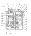
- FIG. 4 shows a cross section thru the.pusher mechanism 24.
- the imput shaft 45 has a helical gear engaging with helical gear 46.
- a concentric, polygonal bore in shaft 45 is aligned with the corresponding bores of the other pusher mechanisms on the conveyor.
- the drive shaft 47 which consists of a polygonal rod extending along the entire length of the conveyor is inserted thru the said bores and coupled to the drive 48.
- the drive 48 is an infinitively variable drive e.g. a DC motor electronically controlled. By all means, when the conveyor is in operation, the drive shaft 47 must turn continuously, at a constant adjustable speed.
- the helical gear 46 has a cylindrical extension which alignes with a cylindrical extension of the same diameter on drive disc 49.
- the upper toe of spring 50 is secured to drive disc 49 by the two pins 51.
- the lower toe engages with the actuator arm 52. If the helical gear 46, which is continuously turning, tends to drive by friction the spring 50 the actuator arm causes the spring to expand, releasing the helical gear 46. When a timed air impulse from the respective section actuates the piston 53 the piston rod pushed the actuator arm 52 and causes it to disengage from the spring toe. The spring closes to its interference fit. The friction contracts the spring 50 so it grips the cylindrical extension of helical gear 46. In this way the drive disc is driven at the same speed as the helical gear 46.
- the slider 64 guided by vertically mounted bearings 65 and by horizontally mounted bearings 66 is forced by roller 62 to make a linear back and forth stroke.
- Slider 64 carries a roller chain 68 wrapped around the two sprockets 67.
- a spring loaded shoe 69 keeps the roller chain under tension.
- the shoe 69 is toothed to prevent the roller chain to slide over it.
- the shoe 69 can also be mounted in a fixed position on main bracket 70 instead of beeing mounted on the slider 64 as shown on FIG. 4 & 5. If mounted on the bracket 70, the shoe will keep the chain fixed relative to the bracket and the other side of the chain will make a stroke which is double the stroke of the slider 64.
- the roller chain 68 engages tangentially with the sprocket 71.
- Sprocket 71 is caused to perform an oscillation. This movement is transmitted by an internal spline engaging with the splined portion of shaft 72 which in turn carries the disc 3.
- the secondary shaft 60 also carries the double cam 73 which actuates the lever 74.
- Lever 74 is centered around the shaft 72 and when the cam rotation causes the lever 74 to rock, the stud 75, supported on one extension of lever 74 moves along an arc of circle.
- Stud 75 carries gear sector 76 which is also guided by its slot engaging with pin 77.
- an air impulse from the respective machine section would start a pusher cycle in which the disc 3 oscilates over an arc of circle and the stud 81 would impart a swinging movement to the pusher arm 4.
- the two motions are compelled according to a definite law, dependent on the dimensions of the various components and in particular on the profile of cam 73, such as to generate at the pusher fingers 5 a path appropriate for a smooth transfer of the objects from the cooling plate onto the conveyor belt.
- the setting knob 9 enables to increase or decrease the swinging motion of the pusher arm 4 around the axis of pivot 81, providing a control of the position of the objects on the conveyor belt.
- the pusher cycle is performed in a shorter time interval than it is required by the machine sections to complete their cycle. If this condition is fullfilled, the pusher mechanism will remain at rest with the clutch spring 50 engaged with the actuator arm 52 until the next impulse from the respective section starts the next cycle. Ideally the pusher cycle should take approximatively 80% of the section cycle, in order that the pusher mechanism is not compelled to move excessively fast. Another requirement is that the. pusher fingers must reach a peripheral speed equal or near to equal to the speed of the conveyor belt. The speed of the conveyor belt, at a given sectional speed, may be considerably different depending on the type of machine.
- a 8-section machine would require a conveyor with a belt moving twice as fast as the conveyor belt of a 4-section machine, always at the same sectional speed. If a pusher mechanism is functioning correctly on a 4-section conveyor, completing its cycle in 80% of the section cycle time, the same pusher, mounted on a 8-section conveyor would have to be set at double-the previous speed in order to match the faster belt speed and would, therefore, complete its cycle in 40% of the section cycle time. In order to avoid this problem, means are available to modulate the rotational speed of the secondary shaft 60, with respect to the primary shaft 56.
- the gears 58 and 59 can be round, elliptical or of any other shape as required, but always with the same number of teeth, so that they complete 1 revolution at the same time. Different sets of gears can be mounted depending on the belt speed requirement of the production machine. Another method of obtaining a similar effect is to move the shaped gears, e.g. elliptical gears, to a different meshing point at the cycle starting position. This would generate a different speed/position characteristic.
- gear 58 is splined and gear 59 mounted on a plain seat and jamned by a nut in order to suit correctly any position of gear 58.
- cam 73 is removed, shifted and reinstalled, the crank 61 is turned by 180 with the gear 58 E 59 out of mesh so that the starting position of roller 62 is the opposite to what it was before, and the shaft 72 is engaged in an other position into the splines of sprocket 71, so that the pivot 81 is, at its starting point, in a mirror opposite position.
- No change of parts is required inside the pusher mechanism; the pusher arm and fingers may need to be of different type for right versus left hand operation.
- the above describes the pusher mechanism as shown on FIG.4. Of course, the same sequence of motions can be obtained with different machine elements.
- a rack secured on slider 64 engaging with a gear centered on shaft 72 could be used.
- a toothed belt could substitute the chain.
- two strips of flexible material, e.g. spring steel, could be fastened at each end of slider 64 and be wrapped around and secured to a pulley mounted on shaft 72.
- sector 76 could be substituted by a lever mounted on the same position, keeping a strip of flexible material at both ends under tension, the said strip turning around a pulley substituting gear 78.
- the system of gears described above could be replaced by a system of roller chain and sprockets, or of toothed belt and pulleys, or flexible strip and pulley.
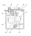
- FIG.9 is showing a cross section of a pusher mechanism electronically driven and controlled.
- Ratiomotor 83 is driving, thru gear 84 and gear 85 the shaft 86 which carries the disc 3 with pivot 81 on which the pusher arm 4 is secured.
- Ratiomotor 87 drives thru its gear 88 the double gear 89. The movement is transmitted from double gear 89 to pivot 81 in the same manner described before.
- a suitable controller would drive the two ratiomotors 83 and 87 according to a definite displacement/ time law such as to generate the correct path and speed at the pusher arm.
- the ratiomotors 83 and 87 could be step-motors or synchronous motors or any other type of motor able to follow precisely a definite displacement/ time function.
- Some production machine are today timed by a mini-computer based controller. With such a device, the impulse starting the pusher cycle could be used intenally to trigger a programmed subroutine which in turn would produce the current output required to drive the motors in the proper manner. In order to obtain different sequences of motion to suit different applications, e.g. different numbers of sections in use, only a change in software would be required.
- the program could be stored in a memory such as a PROM.
- a PROM a memory
- Different programs to suit different applications could be stored in separate exchangeable PROMs which would constitute, in fact, a sort of "electronic cam" producing the desired motion sequence at the pusher arm.
- a controller could also be used with a mechanically or pneumatically timed machine, by means of a transducer converting the starting signal into an electric signal triggering the said microprocessor based controller.
Landscapes
- Chemical & Material Sciences (AREA)
- Engineering & Computer Science (AREA)
- Materials Engineering (AREA)
- Organic Chemistry (AREA)
- Manufacturing & Machinery (AREA)
- Special Conveying (AREA)
- Feeding Of Workpieces (AREA)
- Structure Of Belt Conveyors (AREA)
- Re-Forming, After-Treatment, Cutting And Transporting Of Glass Products (AREA)
Applications Claiming Priority (2)
| Application Number | Priority Date | Filing Date | Title |
|---|---|---|---|
| CH271080 | 1980-04-09 | ||
| CH2710/80 | 1980-04-09 |
Publications (3)
| Publication Number | Publication Date |
|---|---|
| EP0037799A2 true EP0037799A2 (de) | 1981-10-14 |
| EP0037799A3 EP0037799A3 (en) | 1983-10-26 |
| EP0037799B1 EP0037799B1 (de) | 1987-02-11 |
Family
ID=4239848
Family Applications (1)
| Application Number | Title | Priority Date | Filing Date |
|---|---|---|---|
| EP19810810129 Expired EP0037799B1 (de) | 1980-04-09 | 1981-03-31 | Schieber, um Gegenstände von einer Produktionsmaschine, bestehend aus individuellen Segmenten, wegzubewegen |
Country Status (3)
| Country | Link |
|---|---|
| EP (1) | EP0037799B1 (de) |
| JP (1) | JPS56155032A (de) |
| DE (1) | DE3175920D1 (de) |
Cited By (9)
| Publication number | Priority date | Publication date | Assignee | Title |
|---|---|---|---|---|
| DE4411072A1 (de) * | 1993-07-05 | 1995-01-12 | Vidrala Sa | Entnahmegerät für Glas-Hohlkörper aus Formmaschinen |
| EP0676376A3 (de) * | 1994-04-07 | 1996-01-31 | Gps Glasprod Serv Gmbh | Kühlbox zur Anordnung zwischen einer Hohlglasartikelfertigungsmaschine und einem die Hohlglasartikel abfördernden Transportband. |
| FR2763325A1 (fr) * | 1997-05-16 | 1998-11-20 | Emhart Glass Mach Invest | Mecanisme de poussee pour machine sectionnelle |
| DE202004003892U1 (de) * | 2004-03-12 | 2005-04-21 | Heye International Gmbh | Vorrichtung zum Überschieben von Hohlglasgegenständen aus einer Glasformmaschine auf ein Transportband |
| GB2566298A (en) * | 2017-09-07 | 2019-03-13 | Sheppee International Ltd | Tracking system |
| CN112896942A (zh) * | 2021-01-15 | 2021-06-04 | 曾迪 | 一种废料剔除皮带流水线 |
| EP3730462A4 (de) * | 2017-12-20 | 2021-07-07 | Vitro, S.A.B. de C.V. | System und verfahren zum überführen von glasgegenständen |
| CN113165934A (zh) * | 2018-10-22 | 2021-07-23 | Vitro可变资本股份有限公司 | 用于成型玻璃制品的机器的具有单独中空段的支撑块和制造方法 |
| CN114476636A (zh) * | 2021-12-27 | 2022-05-13 | 芜湖亚奇汽车部件有限公司 | 一种汽车油箱防浪板自动上料装置 |
Families Citing this family (1)
| Publication number | Priority date | Publication date | Assignee | Title |
|---|---|---|---|---|
| CN108423418A (zh) * | 2018-03-22 | 2018-08-21 | 王慈 | 一种可以伸缩送料设备 |
Family Cites Families (5)
| Publication number | Priority date | Publication date | Assignee | Title |
|---|---|---|---|---|
| US1911119A (en) * | 1928-05-04 | 1933-05-23 | Hartford Empire Co | Glassware forming machine |
| US1921390A (en) * | 1930-01-04 | 1933-08-08 | Hartford Empire Co | Glassware conveyer |
| US3318433A (en) * | 1965-11-05 | 1967-05-09 | Emhart Corp | Apparatus for moving glass containers onto a moving conveyor |
| US3510288A (en) * | 1967-02-08 | 1970-05-05 | Emhart Corp | Glassware handling apparatus for use with a glassware forming machine to deposit newly formed ware on a take-away conveyor |
| FR2193792A1 (en) * | 1973-07-24 | 1974-02-22 | Emhart Corp | Automatic control of weight of glass articles - using tiltable tube allo-wing for variations in viscosity |
-
1981
- 1981-03-31 DE DE8181810129T patent/DE3175920D1/de not_active Expired
- 1981-03-31 EP EP19810810129 patent/EP0037799B1/de not_active Expired
- 1981-04-09 JP JP5375981A patent/JPS56155032A/ja active Pending
Cited By (13)
| Publication number | Priority date | Publication date | Assignee | Title |
|---|---|---|---|---|
| DE4411072A1 (de) * | 1993-07-05 | 1995-01-12 | Vidrala Sa | Entnahmegerät für Glas-Hohlkörper aus Formmaschinen |
| DE4411072C2 (de) * | 1993-07-05 | 1998-02-12 | Vidrala Sa | Entnahmegerät für Glasflaschen aus einer Formmaschine |
| EP0676376A3 (de) * | 1994-04-07 | 1996-01-31 | Gps Glasprod Serv Gmbh | Kühlbox zur Anordnung zwischen einer Hohlglasartikelfertigungsmaschine und einem die Hohlglasartikel abfördernden Transportband. |
| FR2763325A1 (fr) * | 1997-05-16 | 1998-11-20 | Emhart Glass Mach Invest | Mecanisme de poussee pour machine sectionnelle |
| DE202004003892U1 (de) * | 2004-03-12 | 2005-04-21 | Heye International Gmbh | Vorrichtung zum Überschieben von Hohlglasgegenständen aus einer Glasformmaschine auf ein Transportband |
| US7278282B2 (en) | 2004-03-12 | 2007-10-09 | Heye International Gmbh | Device for transferring hollow glass objects from a glass-forming machine onto a conveyor belt |
| GB2566298A (en) * | 2017-09-07 | 2019-03-13 | Sheppee International Ltd | Tracking system |
| EP3730462A4 (de) * | 2017-12-20 | 2021-07-07 | Vitro, S.A.B. de C.V. | System und verfahren zum überführen von glasgegenständen |
| US11384004B2 (en) | 2017-12-20 | 2022-07-12 | Vitro, S.A.B. De C.V. | System and method for transferring glass items |
| CN113165934A (zh) * | 2018-10-22 | 2021-07-23 | Vitro可变资本股份有限公司 | 用于成型玻璃制品的机器的具有单独中空段的支撑块和制造方法 |
| US12017946B2 (en) | 2018-10-22 | 2024-06-25 | Vitro, S.A.B. De C.V. | Support block with individual hollow sections for a machine for forming glass articles, and manufacturing method |
| CN112896942A (zh) * | 2021-01-15 | 2021-06-04 | 曾迪 | 一种废料剔除皮带流水线 |
| CN114476636A (zh) * | 2021-12-27 | 2022-05-13 | 芜湖亚奇汽车部件有限公司 | 一种汽车油箱防浪板自动上料装置 |
Also Published As
| Publication number | Publication date |
|---|---|
| DE3175920D1 (en) | 1987-03-19 |
| EP0037799B1 (de) | 1987-02-11 |
| EP0037799A3 (en) | 1983-10-26 |
| JPS56155032A (en) | 1981-12-01 |
Similar Documents
| Publication | Publication Date | Title |
|---|---|---|
| EP1803668B1 (de) | Zuführvorrichtung mit einstellbarem Zeitzyklus und Verfahren | |
| US5176244A (en) | High speed variable count mechanical stacker | |
| EP0037799A2 (de) | Schieber, um Gegenstände von einer Produktionsmaschine, bestehend aus individuellen Segmenten, wegzubewegen | |
| US8322513B2 (en) | Apparatus and method for loading food articles | |
| US4414758A (en) | Conveyor for cooling and removal of objects from an in-line sectional production machine | |
| US4768328A (en) | Automatic tray packer | |
| US3899069A (en) | Rotary transfer apparatus for grouping articles | |
| US7220094B2 (en) | Transfer device for cylindrical stacks of products arranged on an edge | |
| EP0736361A2 (de) | Verbesserte Industrieaufschnittschneidmaschine, insbesondere zum Schneiden von Lebensmittelprodukten | |
| EP1003675B1 (de) | Transfermechanismus | |
| US5564894A (en) | Article selection and delivery method and apparatus | |
| EP0806292A2 (de) | Vorrichtung zur Entnahme und zum Einlegen von halbsteifen Kartonbehältern | |
| SU1591911A1 (ru) | Устройство для деления и укладки теста в формы люлек непрерывно движущегося конвейера | |
| CA2595494C (en) | Article selection and delivery method and apparatus | |
| EP0806291A2 (de) | Apparat zur Übergabe von halbstarren Kartonbehältern | |
| WO1990004506A1 (en) | Ribbon holding means in a brick moulding machine | |
| HK1028973B (en) | Transfer mechanism | |
| MXPA97007443A (en) | Apparatus and method for flying and placing articu | |
| SE9100262L (en) | Cam angle variator - varies rotary angle of cam in relation to camshaft for filling regulation in steam machine |
Legal Events
| Date | Code | Title | Description |
|---|---|---|---|
| PUAI | Public reference made under article 153(3) epc to a published international application that has entered the european phase |
Free format text: ORIGINAL CODE: 0009012 |
|
| AK | Designated contracting states |
Designated state(s): DE FR GB IT SE |
|
| 17P | Request for examination filed |
Effective date: 19820203 |
|
| PUAL | Search report despatched |
Free format text: ORIGINAL CODE: 0009013 |
|
| AK | Designated contracting states |
Designated state(s): DE FR GB IT SE |
|
| GRAA | (expected) grant |
Free format text: ORIGINAL CODE: 0009210 |
|
| RAP1 | Party data changed (applicant data changed or rights of an application transferred) |
Owner name: MURIALDO, GASTONE Owner name: PETER, FRITZ |
|
| AK | Designated contracting states |
Kind code of ref document: B1 Designated state(s): DE FR GB IT SE |
|
| PG25 | Lapsed in a contracting state [announced via postgrant information from national office to epo] |
Ref country code: IT Free format text: LAPSE BECAUSE OF FAILURE TO SUBMIT A TRANSLATION OF THE DESCRIPTION OR TO PAY THE FEE WITHIN THE PRESCRIBED TIME-LIMIT;WARNING: LAPSES OF ITALIAN PATENTS WITH EFFECTIVE DATE BEFORE 2007 MAY HAVE OCCURRED AT ANY TIME BEFORE 2007. THE CORRECT EFFECTIVE DATE MAY BE DIFFERENT FROM THE ONE RECORDED. Effective date: 19870211 Ref country code: FR Free format text: THE PATENT HAS BEEN ANNULLED BY A DECISION OF A NATIONAL AUTHORITY Effective date: 19870211 |
|
| PG25 | Lapsed in a contracting state [announced via postgrant information from national office to epo] |
Ref country code: SE Effective date: 19870228 |
|
| REF | Corresponds to: |
Ref document number: 3175920 Country of ref document: DE Date of ref document: 19870319 |
|
| EN | Fr: translation not filed | ||
| GBPC | Gb: european patent ceased through non-payment of renewal fee | ||
| PG25 | Lapsed in a contracting state [announced via postgrant information from national office to epo] |
Ref country code: DE Effective date: 19871201 |
|
| PLBE | No opposition filed within time limit |
Free format text: ORIGINAL CODE: 0009261 |
|
| STAA | Information on the status of an ep patent application or granted ep patent |
Free format text: STATUS: NO OPPOSITION FILED WITHIN TIME LIMIT |
|
| 26N | No opposition filed | ||
| PG25 | Lapsed in a contracting state [announced via postgrant information from national office to epo] |
Ref country code: GB Effective date: 19881118 |