EP0037807A1 - Dispositif de soutènement provisoire d'une galerie ou d'un tunnel - Google Patents
Dispositif de soutènement provisoire d'une galerie ou d'un tunnel Download PDFInfo
- Publication number
- EP0037807A1 EP0037807A1 EP81890020A EP81890020A EP0037807A1 EP 0037807 A1 EP0037807 A1 EP 0037807A1 EP 81890020 A EP81890020 A EP 81890020A EP 81890020 A EP81890020 A EP 81890020A EP 0037807 A1 EP0037807 A1 EP 0037807A1
- Authority
- EP
- European Patent Office
- Prior art keywords
- support bearing
- arm
- lifting cylinder
- frame
- support
- Prior art date
- Legal status (The legal status is an assumption and is not a legal conclusion. Google has not performed a legal analysis and makes no representation as to the accuracy of the status listed.)
- Granted
Links
Images
Classifications
-
- E—FIXED CONSTRUCTIONS
- E21—EARTH OR ROCK DRILLING; MINING
- E21D—SHAFTS; TUNNELS; GALLERIES; LARGE UNDERGROUND CHAMBERS
- E21D11/00—Lining tunnels, galleries or other underground cavities, e.g. large underground chambers; Linings therefor; Making such linings in situ, e.g. by assembling
- E21D11/40—Devices or apparatus specially adapted for handling or placing units of linings or supporting units for tunnels or galleries
- E21D11/403—Devices or apparatus specially adapted for handling or placing units of linings or supporting units for tunnels or galleries combined with the head machine
-
- E—FIXED CONSTRUCTIONS
- E21—EARTH OR ROCK DRILLING; MINING
- E21D—SHAFTS; TUNNELS; GALLERIES; LARGE UNDERGROUND CHAMBERS
- E21D9/00—Tunnels or galleries, with or without linings; Methods or apparatus for making thereof; Layout of tunnels or galleries
- E21D9/10—Making by using boring or cutting machines
- E21D9/1006—Making by using boring or cutting machines with rotary cutting tools
- E21D9/1013—Making by using boring or cutting machines with rotary cutting tools on a tool-carrier supported by a movable boom
- E21D9/102—Making by using boring or cutting machines with rotary cutting tools on a tool-carrier supported by a movable boom by a longitudinally extending boom being pivotable about a vertical and a transverse axis
- E21D9/1026—Making by using boring or cutting machines with rotary cutting tools on a tool-carrier supported by a movable boom by a longitudinally extending boom being pivotable about a vertical and a transverse axis the tool-carrier being rotated about a transverse axis
Definitions
- the invention relates to a device for the provisional removal of a track or tunnel driven near a face by means of a cutting machine, which has a cutting arm which can pivot on all sides and which carries the cutting tool, near the working face, by means of a temporary frame, with a rigid longitudinal member and fixed on the driving machine a feed carrier which can be advanced on this in the direction of the face, on which a transport carriage for transporting the provisional frame can be moved in the longitudinal or longitudinal direction of the tunnel.
- Devices of this type have the advantage that the provisional expansion frames can be transported to the face and set there without the cutting machine having to be moved away from the face. However, it is only possible to set the provisional expansion frames transported to the front by means of the hydraulic rams arranged on the provisional frame itself.
- the longitudinal beam on the cutting machine so that it can pivot about a transverse axis, the front end of the feed beam being pivoted up when it is being set. Even so, only relatively small heights can be managed. Above all, however, the rigid support can only reach so far that the pivoting of the cutting arm is not impaired, and the feed support is freely cantilevered, so that the load bearing capacity of the feed support is limited.
- the object of the invention is to provide a device which allows both the setting and the robbery of the provisional expansion frame at different heights of the driven route or tunnel in a simple manner and at the same time is suitable for absorbing large loads.
- the invention consists essentially in that the Feed carrier is supported in the extended position on a support bearing which is supported against the cutting machine independently of the rigid longitudinal member, and that the trolley is equipped with a lifting mechanism which has a support for the provisional frame. Because the feed carrier itself is supported on a support bearing, the load capacity of the feed carrier is significantly increased. The extendable length of the feed beam can be increased and this enables the rigid beam to protrude less far forward. This again makes it possible to arrange the rigid support deeper without restricting the swiveling range of the cutting arm upwards when the feed support is retracted.
- the arrangement can be made so that the rigid carrier extends over the rear part of the cutting machine and ends at a distance behind the front end of the chassis of the cutting machine, that the support bearing is arranged in front of the front end of the chassis and that the feed carrier after Covering a part of its feed path runs onto the support bearing, the feed carrier being secured against being lifted up from the rigid carrier.
- the rigid support can extend approximately to the middle of the horizontal swivel mechanism for the cutter arm.
- the arrangement is such that the support bearing is arranged at the free end of a link which can be pivoted about a horizontal transverse axis lying transversely to the longitudinal direction of the cutter arm and can be supported against a stop device arranged on the cutter arm base.
- the handlebar When the feed carrier is retracted, however, the handlebar can move freely upwards and is therefore carried along by the cutting arm when it is pivoted upward, so that it releases the movement of the cutting arm.
- the stop device according to an arc, the center of which coincides with the pivot axis for the vertical pivoting of the cutting arm, so that even with each pivoting of the cutting arm in the lower region, the height of the stop device and thus the height of the support bearing remains unchanged and the Cutting arm does not have to be set in an exact position.
- the handlebar is designed as a frame which is articulated on both sides of the swivel mechanism on the transverse axis, the stop device being arranged on both sides of the cutter arm base, and the support bearing is also expediently formed by two support bearing parts, from which each cooperates with a longitudinal beam of the feed beam.
- the support bearing and the stop device can, according to the invention, be equipped with side guides converging towards the support point, so that play in the mounting of the feed carrier on the rigid support and play in the mounting of the handlebar is taken into account.
- the lifting mechanism has two hinged rockers, of which the lower rocker arm is supported by at least one hydraulic lifting cylinder against a bracket to which the lower rocker arm is articulated, and the upper rocker arm by at least one hydraulic lifting cylinder against the lower rocker is supported, which wings can be extended from a fully folded position to a largely extended position.
- This enables large lifting heights, the lifting mechanism being very deep in the retracted position, so that the device can be used both at very low and at very high heights of the route or of the tunnel.
- the rockers are to be actuated in a sequential control in order to move the support carrying the frame as close as possible to the vertical, which according to the invention can be formed by a pin arranged on the upper rocker which engages in a hole in the provisional frame.
- Such a vertical lifting movement for the frame is therefore of particular advantage since the setting point for the frame remains approximately the same regardless of the height of the ridge.
- Such a sequence control can be realized according to the invention in that the rod side of the lifting cylinder engaging the upper rocker arm is hydraulically connected to the piston side of the lifting arm engaging the lower rocker arm and only the piston side of the lifting cylinder engaging the upper rocker arm and only the rod side of the lifting cylinder acting on the lower rocker arm can be hydraulically connected to the pump or the tank.
- the piston side of the lifting cylinder engaging the upper rocker arm is connected to the pump and the rod side of the lifting cylinder engaging the lower rocker arm is connected to the tank, and when the lifting mechanism is lowered, the rod side of the lifting cylinder engaging the lower rocker arm is connected to the pump and the piston side of the lifting cylinder engaging the upper rocker is connected to the tank.
- the console of the hoist can be mounted on the trolley so that it can be moved laterally.
- the lifting mechanism according to the invention is suitable for the application of large forces and the support bearing, which supports the front area of the unit formed by the rigid support and the feed support, enables such large lifting forces to be absorbed.
- This makes it possible to transport and set heavy expansion elements, which for example weigh over 100 kg.
- this also enables the caps of the final expansion to be transported and brought to the setting points.
- the provisional frames have a suspension device, for example a hook, on the side of their cap for the suspension of a cap of a final expansion frame, it being irrelevant that this increases the transport weight even further. This has a decisive advantage in mine operations.
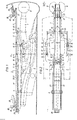
- FIG. 1 and 2 show the device in a side view and a top view, the outlines of the cutting machine itself being only indicated by dash-dotted lines.
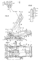
- 3 and 4 show in larger scale the trolley in side view and plan view on a larger scale, the extended position is shown in dashed lines in Fig. 3.
- Fig. 5 shows schematically the control of the hoist.
- a rigid support 3 is firmly connected to the cutting machine by two supports 4 and 5.
- the line 6 denotes the center of the swivel mechanism for the cutting arm 7, which has cutting heads 8 at its protruding end.
- Line 6 represents the vertical axis about which the cutting arm 7 can be pivoted horizontally.
- 9 is the horizontal axis about which the cutting arm 7 can be pivoted in the vertical direction.
- the front end 10 of the rigid support 3 extends only up to the center of the swivel mechanism, designated 6.
- a feed support 11 is slidably mounted, which can be moved from the position 11 'shown in broken lines, in which it does not protrude beyond the front end 10 of the rigid support 3, in the fully drawn position 11 in the direction of the face 12.
- a pair of rollers 13 is arranged at the front end 10 of the rigid support 3.
- the feed carrier 11 also has a pair of rollers 14 which is guided between the flanges of the U-shaped longitudinal bars of the rigid carrier 3.
- a support bearing 15 which has rollers 16.
- the feed carrier 11 runs on this support bearing 15 after part of its feed path.
- the support bearing 15 is arranged at the free end of a link 17 which is mounted in the middle 6 of the swivel mechanism 18 at 19 on the swivel mechanism 18.
- the handlebar is against one in the middle Supported stop device 20 which is arranged on the cutter arm base 21. In an approximately horizontal or downwardly inclined position of the cutting arm 7, the link 17 rests on the stop device 20, so that the support bearing 15 supports the feed carrier 11.
- the bearing surface 22 of this stop device 20 is shaped according to a circular arc, the center of which lies in the pivot axis 9 of the cutting arm, so that the height of the support bearing 15 remains the same in all positions of the cutting arm 7 in the lower region.
- the handlebar 17 is formed by a frame, i.e. a pair of links 17-17 is provided, which is connected by a cross member 23. There are therefore provided on both sides of the cutter arm stop devices 20, and the support bearing 15 is double on the cross member 23, with each longitudinal beam 24, a support bearing part 15 cooperates with rollers 16.
- the support bearing 15 has converging side guides 25 in order to ensure the correct running in of the feed carrier 11.
- the stop device also has converging side guides 26.
- a transport carriage 27, which carries a lifting mechanism 29, can be moved on rollers 28 on the feed carrier 11.
- the transport carriage 27 is shown on the left in dashed lines.
- the transport carriage 27 can reach this position when the feed carrier is retracted, and in this position it can be used to rob the provisional expansion frame 30.
- the provisional frames 30, as shown in FIG. 3 on a larger scale, have a recess 31 into which a pin 32 of the lifting mechanism 29 engages.
- the feed carrier 11 is moved to the face 12, for which purpose a cable 33 is provided which is actuated by a winch 34, is guided over a deflection roller 35 mounted on the rigid carrier 3 and is fastened at 36 to the feed carrier 11.
- a second cable 37 is used to retract the feed beam 11.
- the trolley 27 In the out to face Driving position, the trolley 27 is shown in full lines. In this position, the provisional frame can be placed near the face 12.
- the lifting mechanism 29 consists of two rockers 38 and 39.
- the lower rocker 38 is mounted at 40 on a bracket 41.
- the upper rocker 39 is connected by means of a joint 42 to the free end of the lower rocker 38 and carries at its free end the support for the provisional frame formed by the pin 32.
- a lifting cylinder 44 is hinged to the lower rocker 38 at 43, the other end of which is hinged at 45 to the bracket 41.
- a second lifting cylinder 47 is articulated at 46, which is attached to the lower rocker 38 at 48.
- a sequence control is provided, which is indicated in FIG. 5.
- the piston side 49 of the lifting cylinder 47 is connected to the pump.
- the rod side 50 of the lifting cylinder 47 is in constant communication with the piston side 52 of the lifting cylinder 44 via a line 51, while the rod side 53 of the lifting cylinder 44 is connected to the tank.
- the piston in the lifting cylinder 44 is thus only displaced as a function of the movement of the piston in the lifting cylinder 47.
- the rod side 53 of the lifting cylinder 44 is connected to the pump and the piston side 49 of the lifting cylinder 47 to the tank during the pulling-in movement.
- the bracket 41 is mounted on the transport carriage 27 so as to be transversely displaceable by slide guides 54 and can be displaced transversely by means of a hydraulic cylinder 55 in order to place the provisional expansion frame in the middle of the roof.
- a hook 56 is provided on the side of the provisional expansion frame 30, from which the caps 57 of the permanent expansion can be hung. It is therefore possible to transport these caps 57 of the permanent expansion with the provisional frames to the working face, and the permanent expansion frames can already be completed with the caps 57 in the area of the cutting machine and placed next to the provisional expansion frames. This saves a significant amount of time.
Landscapes
- Engineering & Computer Science (AREA)
- Mining & Mineral Resources (AREA)
- Geology (AREA)
- Life Sciences & Earth Sciences (AREA)
- General Life Sciences & Earth Sciences (AREA)
- Geochemistry & Mineralogy (AREA)
- Environmental & Geological Engineering (AREA)
- Architecture (AREA)
- Civil Engineering (AREA)
- Structural Engineering (AREA)
- Forklifts And Lifting Vehicles (AREA)
- Ship Loading And Unloading (AREA)
- Handcart (AREA)
Applications Claiming Priority (2)
| Application Number | Priority Date | Filing Date | Title |
|---|---|---|---|
| AT0187180A AT366776B (de) | 1980-04-04 | 1980-04-04 | Vorrichtung fuer das provisorische ausbauen einer strecke oder eines tunnels |
| AT1871/80 | 1980-04-04 |
Publications (2)
| Publication Number | Publication Date |
|---|---|
| EP0037807A1 true EP0037807A1 (fr) | 1981-10-14 |
| EP0037807B1 EP0037807B1 (fr) | 1983-11-23 |
Family
ID=3522808
Family Applications (1)
| Application Number | Title | Priority Date | Filing Date |
|---|---|---|---|
| EP81890020A Expired EP0037807B1 (fr) | 1980-04-04 | 1981-01-30 | Dispositif de soutènement provisoire d'une galerie ou d'un tunnel |
Country Status (7)
| Country | Link |
|---|---|
| EP (1) | EP0037807B1 (fr) |
| AT (1) | AT366776B (fr) |
| CS (1) | CS222195B2 (fr) |
| DE (1) | DE3161455D1 (fr) |
| IN (1) | IN153072B (fr) |
| PL (1) | PL127964B1 (fr) |
| SU (1) | SU1213991A3 (fr) |
Cited By (17)
| Publication number | Priority date | Publication date | Assignee | Title |
|---|---|---|---|---|
| DE3145272A1 (de) * | 1981-11-14 | 1983-06-01 | GTA GmbH Fertigungsbetrieb und Ingenieurbüro für Grubenbedarf, Transport- und Ausbautechnik, 4236 Hamminkeln | Als ausbau- und bohrhilfe dienende vorrichtung fuer den streckenvortrieb im berg- und tunnelbau. |
| FR2546229A1 (fr) * | 1983-05-17 | 1984-11-23 | Voest Alpine Ag | Dispositif de soutenement d'une galerie |
| FR2546228A1 (fr) * | 1983-05-17 | 1984-11-23 | Voest Alpine Ag | Dispositif de mise en place de cintres de galeries pres d'une machine de creusement a decoupe partielle |
| AT386460B (de) * | 1986-08-20 | 1988-08-25 | Voest Alpine Ag | Einrichtung zum befestigen von verzugselementen in einer strecke nahe der ortsbrust |
| WO1988009426A1 (fr) * | 1987-05-23 | 1988-12-01 | Anderson Strathclyde Plc | Excavatrice a mouvement circulaire |
| DE3339678C1 (de) * | 1983-11-02 | 1989-06-29 | GTA GmbH Fertigungsbetrieb und Ingenieurbüro für Grubenbedarf, Transport- und Ausbautechnik, 4236 Hamminkeln | Ausbausetzeinrichtung für den Vortrieb mit einer Teilschnittmaschine |
| EP1298283A1 (fr) * | 2001-09-28 | 2003-04-02 | Gta Maschinensysteme Gmbh | Machine de creusement de tunnels |
| JP2009191565A (ja) * | 2008-02-18 | 2009-08-27 | Hazama Corp | トンネル掘削装置 |
| US8485608B2 (en) | 2008-10-28 | 2013-07-16 | Sandvik Mining And Construction G.M.B.H. | Heading or extraction machine |
| CN109869169A (zh) * | 2019-04-03 | 2019-06-11 | 蓝传雯 | 一种拱架装夹臂架 |
| CN110295930A (zh) * | 2019-07-13 | 2019-10-01 | 河北能源职业技术学院 | 用于较薄煤层采煤工作面的液压支架起运装置 |
| CN111270704A (zh) * | 2020-01-03 | 2020-06-12 | 中铁工程机械研究设计院有限公司 | 安装车的调整机构 |
| CN111980703A (zh) * | 2020-08-31 | 2020-11-24 | 中国矿业大学 | 一种地下水库煤柱坝体侧向切顶卸压设备及切顶卸压方法 |
| CN112795713A (zh) * | 2019-11-13 | 2021-05-14 | 上海耀秦冶金设备技术有限公司 | 摇摆式渣处理罐及使用该渣处理罐的渣处理装备 |
| CN112832759A (zh) * | 2021-02-25 | 2021-05-25 | 天地上海采掘装备科技有限公司 | 具有良好工作环境的采煤机摇臂摆动机构 |
| CN113756830A (zh) * | 2021-08-20 | 2021-12-07 | 鄂尔多斯市绿矿技术服务有限公司 | 连采连充工作面支巷快速掘进方法 |
| CN118223924A (zh) * | 2024-05-27 | 2024-06-21 | 安徽恒源煤电股份有限公司祁东煤矿 | 一种井下定向长钻孔水力压裂卸压护巷装置及防护方法 |
Families Citing this family (3)
| Publication number | Priority date | Publication date | Assignee | Title |
|---|---|---|---|---|
| ZA201201175B (en) * | 2011-02-18 | 2012-10-31 | Joy Mm Delaware Inc | Roof support sheet handling for underground mines |
| CN113685217B (zh) * | 2021-09-30 | 2024-12-20 | 内蒙古绿矿科技有限公司 | 一种迈步自移式临时支护装备及其支护方法 |
| CN114109445A (zh) * | 2021-11-07 | 2022-03-01 | 重庆交通大学 | 一种利用临时竖向支撑减跨的大跨度隧道全断面施工方法 |
Citations (1)
| Publication number | Priority date | Publication date | Assignee | Title |
|---|---|---|---|---|
| DE2145076B2 (de) * | 1970-09-11 | 1977-10-27 | Coal Industry (Patents) Ltd, London | Verfahren zum auffahren von abbaustrecken und vortriebsmaschine zur durchfuehrung des verfahrens |
Family Cites Families (8)
| Publication number | Priority date | Publication date | Assignee | Title |
|---|---|---|---|---|
| DE2462542C3 (de) * | 1974-08-05 | 1984-10-25 | Gewerkschaft Eisenhütte Westfalia, 4670 Lünen | Teilschnitt-Vortriebsmaschine für den Vortrieb von Tunneln, Stollen oder sonstigen Strecken |
| FR2309705A1 (fr) * | 1975-04-30 | 1976-11-26 | Lorraine Houilleres | Machine elevatrice de chapeau de soutenement |
| DE2558647A1 (de) * | 1975-12-24 | 1977-06-30 | Paurat F | Anordnung zum vortrieb von strecken und zum einbringen von streckenausbau |
| DE2621674C3 (de) * | 1976-05-15 | 1978-11-09 | Bochumer Eisenhuette Heintzmann Gmbh & Co, 4630 Bochum | Verfahren und Vorrichtung zum Vortrieb und Ausbau einer untertägigen Strecke sowie Streckenausbau zur Ausübung des Verfahrens |
| DE2655348A1 (de) * | 1976-12-07 | 1978-06-08 | Eickhoff Geb | Teilschnittvortriebsmaschine zum auffahren von tunnels oder strecken |
| AT353733B (de) * | 1977-10-13 | 1979-11-26 | Voest Ag | Vorrichtung fuer das provisorische ausbauen einer strecke oder eines tunnels |
| DE2801181C2 (de) * | 1978-01-12 | 1986-10-09 | Gewerkschaft Eisenhütte Westfalia GmbH, 4670 Lünen | Einrichtung zur Vormontage von mehrteiligen Ausbaurahmen beim maschinellen Vortrieb von Untertagestrecken, Tunneln, Stollen u.dgl. mittels einer Teilschnittmaschine |
| DE2813143C3 (de) * | 1978-03-25 | 1980-12-04 | Bochumer Eisenhuette Heintzmann Gmbh & Co, 4630 Bochum | Vorrichtung zum Vortreiben und Ausbauen einer untertägigen Strecke |
-
1980
- 1980-04-04 AT AT0187180A patent/AT366776B/de not_active IP Right Cessation
-
1981
- 1981-01-30 DE DE8181890020T patent/DE3161455D1/de not_active Expired
- 1981-01-30 EP EP81890020A patent/EP0037807B1/fr not_active Expired
- 1981-02-16 IN IN174/CAL/81A patent/IN153072B/en unknown
- 1981-03-17 SU SU813259153A patent/SU1213991A3/ru active
- 1981-03-23 CS CS812093A patent/CS222195B2/cs unknown
- 1981-03-25 PL PL1981230321A patent/PL127964B1/pl unknown
Patent Citations (1)
| Publication number | Priority date | Publication date | Assignee | Title |
|---|---|---|---|---|
| DE2145076B2 (de) * | 1970-09-11 | 1977-10-27 | Coal Industry (Patents) Ltd, London | Verfahren zum auffahren von abbaustrecken und vortriebsmaschine zur durchfuehrung des verfahrens |
Cited By (24)
| Publication number | Priority date | Publication date | Assignee | Title |
|---|---|---|---|---|
| DE3145272A1 (de) * | 1981-11-14 | 1983-06-01 | GTA GmbH Fertigungsbetrieb und Ingenieurbüro für Grubenbedarf, Transport- und Ausbautechnik, 4236 Hamminkeln | Als ausbau- und bohrhilfe dienende vorrichtung fuer den streckenvortrieb im berg- und tunnelbau. |
| FR2546229A1 (fr) * | 1983-05-17 | 1984-11-23 | Voest Alpine Ag | Dispositif de soutenement d'une galerie |
| FR2546228A1 (fr) * | 1983-05-17 | 1984-11-23 | Voest Alpine Ag | Dispositif de mise en place de cintres de galeries pres d'une machine de creusement a decoupe partielle |
| DE3416385A1 (de) * | 1983-05-17 | 1984-11-29 | Voest-Alpine Ag, Linz | Einrichtung zum setzen von streckenboegen |
| AT377330B (de) * | 1983-05-17 | 1985-03-11 | Voest Alpine Ag | Einrichtung zum setzen von streckenboegen |
| AT377574B (de) * | 1983-05-17 | 1985-04-10 | Voest Alpine Ag | Einrichtung fuer das ausbauen einer strecke |
| DE3339678C1 (de) * | 1983-11-02 | 1989-06-29 | GTA GmbH Fertigungsbetrieb und Ingenieurbüro für Grubenbedarf, Transport- und Ausbautechnik, 4236 Hamminkeln | Ausbausetzeinrichtung für den Vortrieb mit einer Teilschnittmaschine |
| AT386460B (de) * | 1986-08-20 | 1988-08-25 | Voest Alpine Ag | Einrichtung zum befestigen von verzugselementen in einer strecke nahe der ortsbrust |
| WO1988009426A1 (fr) * | 1987-05-23 | 1988-12-01 | Anderson Strathclyde Plc | Excavatrice a mouvement circulaire |
| GB2230032A (en) * | 1987-05-23 | 1990-10-10 | Anderson Strathclyde Plc | Circular heading machine |
| GB2230032B (en) * | 1987-05-23 | 1991-10-16 | Anderson Strathclyde Plc | Circular heading machine |
| EP1298283A1 (fr) * | 2001-09-28 | 2003-04-02 | Gta Maschinensysteme Gmbh | Machine de creusement de tunnels |
| JP2009191565A (ja) * | 2008-02-18 | 2009-08-27 | Hazama Corp | トンネル掘削装置 |
| US8485608B2 (en) | 2008-10-28 | 2013-07-16 | Sandvik Mining And Construction G.M.B.H. | Heading or extraction machine |
| CN109869169A (zh) * | 2019-04-03 | 2019-06-11 | 蓝传雯 | 一种拱架装夹臂架 |
| CN109869169B (zh) * | 2019-04-03 | 2023-10-20 | 四川蓝海智能装备制造有限公司 | 一种拱架装夹臂架 |
| CN110295930A (zh) * | 2019-07-13 | 2019-10-01 | 河北能源职业技术学院 | 用于较薄煤层采煤工作面的液压支架起运装置 |
| CN112795713A (zh) * | 2019-11-13 | 2021-05-14 | 上海耀秦冶金设备技术有限公司 | 摇摆式渣处理罐及使用该渣处理罐的渣处理装备 |
| CN111270704A (zh) * | 2020-01-03 | 2020-06-12 | 中铁工程机械研究设计院有限公司 | 安装车的调整机构 |
| CN111980703A (zh) * | 2020-08-31 | 2020-11-24 | 中国矿业大学 | 一种地下水库煤柱坝体侧向切顶卸压设备及切顶卸压方法 |
| CN112832759A (zh) * | 2021-02-25 | 2021-05-25 | 天地上海采掘装备科技有限公司 | 具有良好工作环境的采煤机摇臂摆动机构 |
| CN113756830A (zh) * | 2021-08-20 | 2021-12-07 | 鄂尔多斯市绿矿技术服务有限公司 | 连采连充工作面支巷快速掘进方法 |
| CN113756830B (zh) * | 2021-08-20 | 2022-07-05 | 鄂尔多斯市绿矿技术服务有限公司 | 连采连充工作面支巷快速掘进方法 |
| CN118223924A (zh) * | 2024-05-27 | 2024-06-21 | 安徽恒源煤电股份有限公司祁东煤矿 | 一种井下定向长钻孔水力压裂卸压护巷装置及防护方法 |
Also Published As
| Publication number | Publication date |
|---|---|
| CS222195B2 (en) | 1983-05-27 |
| IN153072B (fr) | 1984-05-26 |
| EP0037807B1 (fr) | 1983-11-23 |
| AT366776B (de) | 1982-05-10 |
| ATA187180A (de) | 1981-09-15 |
| DE3161455D1 (en) | 1983-12-29 |
| PL127964B1 (en) | 1983-12-31 |
| PL230321A1 (fr) | 1981-11-13 |
| SU1213991A3 (ru) | 1986-02-23 |
Similar Documents
| Publication | Publication Date | Title |
|---|---|---|
| EP0037807B1 (fr) | Dispositif de soutènement provisoire d'une galerie ou d'un tunnel | |
| AT512457B1 (de) | Vortriebs- oder gewinnungsmaschine | |
| DE2840919C3 (de) | An einer Streckenvortriebsmaschine angeordnete Vorrichtung zum Einbringen von Ausbaurahmen eines provisorischen Streckenausbaus | |
| DE2656703C2 (de) | Abbaumaschine | |
| DE2720380C2 (de) | Vortriebsmaschine | |
| DE3445062C2 (fr) | ||
| DE3122647A1 (de) | Gleisbearbeitungsmaschine mit hebe- und richtwerkzeugen | |
| DE2323811A1 (de) | Stuetzrahmen fuer schreitbare gestelle fuer vortriebsarbeiten | |
| AT5578U1 (de) | Vortriebs- oder gewinnungsmaschine | |
| DE1921314C3 (de) | Schreitwerk für Vortriebs- oder Ladevorrichtung in Bergbaubetrieben | |
| DE2450003C2 (de) | Fahrzeugkran mit Kabine mit verschiedenen Stellungen | |
| DE2950076C2 (de) | Arbeitsbühne für Streckenvortrieb im Untertage- und Tunnelbau | |
| AT392512B (de) | Schraemmaschine | |
| DE3020770C2 (de) | Fahrzeug für den Ausbau von Gruben und Tunnelbauten | |
| DE3153022A1 (de) | Als ausbau- und bohrhilfe dienende vorrichtung fuer den streckenvortrieb im berg- und tunnelbau | |
| DE2353230C2 (de) | Gewinnungseinrichtung, insbesondere für den schwebenden Abbau in halbsteiler oder steiler Lagerung | |
| DE2646496A1 (de) | Einrichtung zum fortlaufenden ausbau einer strecke | |
| DE2008412C3 (de) | Walzenschrämmaschine | |
| DE3441697C1 (de) | Streckenvortriebsmaschine, insbesondere zum Auffahren von Abbaustrecken | |
| DE2806792C2 (de) | Teilschnittvortriebsmaschine | |
| DE2533903C3 (de) | Schreitende Ausbaueinheit für den Strebausbau im Bereich des Streb-Streckenüberganges und für die Verlagerung der Antriebsstation eines Strebförderers und/oder einer Gewinnungseinrichtung | |
| DE948232C (de) | Streckenvortriebsmaschine | |
| DE3301530C2 (fr) | ||
| DE3320123C2 (de) | Vorrichtung zum Vortreiben von Strecken mittels einer Walzenschrämmaschine | |
| DE3145272A1 (de) | Als ausbau- und bohrhilfe dienende vorrichtung fuer den streckenvortrieb im berg- und tunnelbau. |
Legal Events
| Date | Code | Title | Description |
|---|---|---|---|
| PUAI | Public reference made under article 153(3) epc to a published international application that has entered the european phase |
Free format text: ORIGINAL CODE: 0009012 |
|
| AK | Designated contracting states |
Designated state(s): DE FR GB |
|
| 17P | Request for examination filed |
Effective date: 19811009 |
|
| GRAA | (expected) grant |
Free format text: ORIGINAL CODE: 0009210 |
|
| AK | Designated contracting states |
Designated state(s): DE FR GB |
|
| REF | Corresponds to: |
Ref document number: 3161455 Country of ref document: DE Date of ref document: 19831229 |
|
| ET | Fr: translation filed | ||
| PGFP | Annual fee paid to national office [announced via postgrant information from national office to epo] |
Ref country code: FR Payment date: 19840125 Year of fee payment: 4 |
|
| PLBE | No opposition filed within time limit |
Free format text: ORIGINAL CODE: 0009261 |
|
| STAA | Information on the status of an ep patent application or granted ep patent |
Free format text: STATUS: NO OPPOSITION FILED WITHIN TIME LIMIT |
|
| 26N | No opposition filed | ||
| PGFP | Annual fee paid to national office [announced via postgrant information from national office to epo] |
Ref country code: DE Payment date: 19850131 Year of fee payment: 5 |
|
| GBPC | Gb: european patent ceased through non-payment of renewal fee | ||
| PG25 | Lapsed in a contracting state [announced via postgrant information from national office to epo] |
Ref country code: FR Free format text: LAPSE BECAUSE OF NON-PAYMENT OF DUE FEES Effective date: 19870930 |
|
| PG25 | Lapsed in a contracting state [announced via postgrant information from national office to epo] |
Ref country code: DE Effective date: 19871001 |
|
| REG | Reference to a national code |
Ref country code: FR Ref legal event code: ST |
|
| PG25 | Lapsed in a contracting state [announced via postgrant information from national office to epo] |
Ref country code: GB Effective date: 19881118 |