EP0037955A2 - Appareil mélangeur - Google Patents
Appareil mélangeur Download PDFInfo
- Publication number
- EP0037955A2 EP0037955A2 EP81102413A EP81102413A EP0037955A2 EP 0037955 A2 EP0037955 A2 EP 0037955A2 EP 81102413 A EP81102413 A EP 81102413A EP 81102413 A EP81102413 A EP 81102413A EP 0037955 A2 EP0037955 A2 EP 0037955A2
- Authority
- EP
- European Patent Office
- Prior art keywords
- base
- primary control
- control line
- control circuit
- support
- Prior art date
- Legal status (The legal status is an assumption and is not a legal conclusion. Google has not performed a legal analysis and makes no representation as to the accuracy of the status listed.)
- Granted
Links
Images


Classifications
-
- B—PERFORMING OPERATIONS; TRANSPORTING
- B01—PHYSICAL OR CHEMICAL PROCESSES OR APPARATUS IN GENERAL
- B01F—MIXING, e.g. DISSOLVING, EMULSIFYING OR DISPERSING
- B01F31/00—Mixers with shaking, oscillating, or vibrating mechanisms
- B01F31/20—Mixing the contents of independent containers, e.g. test tubes
- B01F31/22—Mixing the contents of independent containers, e.g. test tubes with supporting means moving in a horizontal plane, e.g. describing an orbital path for moving the containers about an axis which intersects the receptacle axis at an angle
Definitions
- the present invention relates generally to apparatus for producing a vortex and to the mixing of liquids contained in laboratory vessels such as test tubes.
- this invention provides both an improved structural arrangement for supporting a hold down plate relative to a base and an agitated platform and an improved motor control circuit for initiating the formation of a vortex.
- Motor control circuits for existing vortexers customarily provide circuitry for operating the motor with time control or, alternatively, in a continuous mode of operation.
- Speed control circuits have also been utilized.
- the present invention provides an improved motor control circuit wherein the electric motor is energized to produce an immediate vortex although the speed control may be set extremely low. This feature is of particular advantage in overcoming the intertia of rest characteristic of such systems, and to assure consistency in the result of a timed cycle of operation.
- the present invention provides a vortexer apparatus having a base, .a motor mounted to said base, an agitated platform resiliently supported from said base and connected to said motor by an eccentric crank, and a hold down plate, characterized by an upright cylindrical support mounted to said base, said support having a pair of splines formed thereon, the end of one spline being spaced from the near end of the other spline by a circumferential groove; and means for detachably mounting said hold down plate to said support including an elongate sleeve axially engageable with said support and having a key engageable with said pair of splines and groove; whereby said plate may be selectively mounted on said support at alternative positions, said key being engageable with either one of said splines or with said circumferential groove.
- the present invention also provides a control circuit for an electric motor of a vortexer comprising a primary control line including a primary control switch for starting and stopping the motor; means for applying a current to said primary control line; means for operating said primary control switch and selectively conditioning said primary control line to be either conductive or non-conductive; a speed control circuit including a secondary control line connected to said primary control line for pulsing the current flow and varying the pulse width of the current carried through said primary control line; and a start-up control line connected to said primary control line for conducting a current of substantially full pulse width for a time period sufficient to overcome the intertia at rest of the vortexer and supported apparatus.
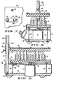
- the vortexer apparatus generally comprises a base 10, a motor 11 mounted to said base, an agitated platform 12 resiliently supported from the base and connected to motor 11 by an eccentric crank and coupling 13. Agitated platform 12 is resiliently supported upon a set of four wires 14, the lower end of each wire being secured in a holder 15 mounted to base 10.
- a housing 16 essentially encloses motor 11, wire 14 and the operating circuitry of the vortexer. This arrangement of apparatus is essentially known and is utilized in connection with other forms of vortexer apparatus.
- the present invention is more especially directed to the means provided for mounting a hold down plate 20 relative to agitated plate 12 and base 10.
- a cylindrical support spindle 21 secured to base 10 by a screw 22, and amintained upright by housing 16.
- a torque arm 23 is fitted to the lower portion of support spindle 21, and made a part thereof either with a force fit or by welding, and the torque arm is secured to the housing 16 by a set screw 24.
- Torque arm 23 is provided with a slot 23a which allows the torque arm to be angularly pivoted relative to the base through small angles of adjustment and then secured by set screw 24 when properly located.
- Slight angular adjustments of the torque arm and support spindle 21 are made by an eccentric 25 threadably received in housing 16.
- the upper end of eccentric 25 carries a pin 25a, said pin being offset relative to the axis of threading and received in an opening 23b of the torque arm. This arrangement is best shown in Fig. 7.
- the angular orientation of support spindle 21 is of importance in locating the hold down plate 20 directly above agitated platform 12.
- the mechanism provided for angularly positioning spindle 21 allows this to be done quite easily at the time of assembly, notwithstanding a manufacture of parts which may vary slightly in size and be built to loose tolerances.
- Support spindle 21 is formed with a pair of splines 21a and 21b, the lower end of upper spline 21a being spaced from the upper end of lower spline 21b by a circumferential groove 21c. It will be further noted that the pair of splines 21a and 21b are formed on opposite sides of support 21 in an axial misalignment relative to each other.
- Plate 20 is adapted to be mounted to and supported from spindle 21 through an elongate sleeve 26, the internal diameter of sleeve 26 being only slightly greater than the outer diameter of support spindle 21.
- a key 27 is secured to sleeve 26, said key being engageable with either of said pair of splines 21a or 21b, or groove 21c, when properly aligned therewith. In the position shown in Figs. 5 and 6, key 27 is engaged with spline 21b, and in that position allows hold down plate 20 to be lowered upon a set of laboratory test tubes T supported in a rack R. Although the weight of plate 20 may be sufficient to hold the upper ends of each tube T in a relatively fixed or steady position, the hold down pressure may be increased.
- a set screw 28 is provided to secure sleeve 26 at a set position along support spindle 21.
- hand pressure is applied to the top of plate 20 with set screw 28 backed off.
- set screw 28 is then threaeded into engagement with the surface of spindle 21.
- indentations may be formed along spindle 21 to receive the end of the set screw in various "set" positions.
- Fig. 1 illustrates in broken line a position for hold down plate 20 allowing removal of rack R and test tubes T. This position is attained simply by backing off set screw 28, lifting table 20 until key 27 extends beyond spline 21b and becomes aligned with groove 21c, and then rotating plate 20. Key 27 will then track within groove 21c supporting table 20 at that position.
- table 20 and sleeve 26 may be removed entirely from spindle 21 by simply rotating plate 20 until key 27 becomes aligned with groove 21a, then lifting the table and sleeve 26 axially from the spindle support.
- Figs. 2, 3 and 4 illustrate various types of racks and vessels which may be utilized in connection with the vortexer. Such racks and vessels are commonly known and used in connection with other vortexers.
- Fig. 8 is a schematic of a preferred embodiment of a control circuit for energizing an electric motor in accordance with this invention.
- motor 11 is adapted to be energized with a pulsating DC current through an energizing circuit, including the rectifying bridge 31, a darlington pair of switches 32 and 33, and a control switch 34.
- the base of control switch 34 is optically coupled to a control circuit through an integrated circuit 35 including an LED.
- both the energizing circuit and the optical coupler 35 are considered part of the prior art.
- This invention more particularly relates to the control circuit for operating the LED of circuit 35, both with respect to time and duration, as to control and energize motor 11.
- control circuit shown comprises a primary control line 36, including a primary control switch 37.
- Control line 36 is connected to a rectifying bridge which serves as a means for applying a direct current thereto.
- a pulsing of the current flow through control line 36 is produced by a speed control circuit, including a secondary control line 38 connected to line 36 through a diode 39, an integrated circuit 40, and a ground line 41.
- the integrated circuit 40 is commercially known and available as a timer circuit, and is currently sold by Signatics, Inc. under the trade designation NE555.
- the functional pin arrangement of this integrated circuit is as follows:
- Integrated circuit 40 operates as a multivibrator in connection with a pair of variable resisters 42 and 43 and a capacitor 44.
- Variable resisters 42 and 43 serve as low and high speed adjustments respectively.
- An adjustment of the variable resistances controls the pulse width of the signal generated by the multivibrator and an adjustment in resistance varies the pulse width or duty cycle. It will be further apparent that this operation also controls the duty cycle and frequency of the current flowing through control line 36, secondary control line 38 and ground line 41.
- the control circuit shown may. be energized either on a time control basis or continuously.
- a manually operated switch 45 having a pair of moveable contacts 45a and 45b, controls the on-off time of switch 37.
- switch 45 When switch 45 is operated to place moveable contacts 45a and 45b to the "on" position, a positive current flows to the base of switch 37 through line'46, resistance 47 and a control line 48.
- switch 45 In the "time" mode of operation, switch 45 is operated to momentarily place the moveable contacts 45a and 45b in their alternate positions. A positive current then flows to the base of switch'37 from an integrated circuit 49 which is identical to the integrated circuit 40. Placing the moveable contact 45b on the fixed contact related to "time” connects pin 2 of the integrated circuit 49 to ground and by reason of its timer configuration a positive current flows to the base of switch 37 through a diode 50. The duration of this condition of operation is determined by the setting of a variable resister 51, a fixed resistance 52 and a capacitor 53. When capacitor 53 becomes charged, pin 3 of integrated circuit 49 and the base of switch 37, assume ground potential. Switch 37 then opens.
- An important feature of the present invention is in providing an initial high starting current for energizing motor 11. This is accomplished with a start-up control line 54, including a diode 55 and a switch 56.
- This start-up control line provides a flow path from primary control line 36 for conducting a current having substantially full pulse width. But the time or duration of the current flow through switch 56 is only momentary or of a period sufficient to overcome the inertia at rest of the vortexer and supported apparatus.
- the base of switch 56 connects to control line 48 through a resistance 57, and a capacitor 58 is provided between resistance 57 and ground. The values of resistance 57 and capacitor 58 are then chosen to close switch 56 after a selected time period. It has been found that 15 to 20 milliseconds is adequate to overcome the energy of rest characteristic of one type of vortexer and its supported apparatus.
Landscapes
- Chemical & Material Sciences (AREA)
- Chemical Kinetics & Catalysis (AREA)
- Devices For Use In Laboratory Experiments (AREA)
- Sampling And Sample Adjustment (AREA)
- Structures Of Non-Positive Displacement Pumps (AREA)
Priority Applications (1)
| Application Number | Priority Date | Filing Date | Title |
|---|---|---|---|
| AT81102413T ATE6130T1 (de) | 1980-04-08 | 1981-03-31 | Mischgeraet. |
Applications Claiming Priority (4)
| Application Number | Priority Date | Filing Date | Title |
|---|---|---|---|
| US13841780A | 1980-04-08 | 1980-04-08 | |
| US06/138,416 US4305668A (en) | 1980-04-08 | 1980-04-08 | Vortexer |
| US138417 | 1980-04-08 | ||
| US138416 | 1980-04-08 |
Publications (3)
| Publication Number | Publication Date |
|---|---|
| EP0037955A2 true EP0037955A2 (fr) | 1981-10-21 |
| EP0037955A3 EP0037955A3 (en) | 1982-01-20 |
| EP0037955B1 EP0037955B1 (fr) | 1984-02-08 |
Family
ID=26836179
Family Applications (1)
| Application Number | Title | Priority Date | Filing Date |
|---|---|---|---|
| EP81102413A Expired EP0037955B1 (fr) | 1980-04-08 | 1981-03-31 | Appareil mélangeur |
Country Status (2)
| Country | Link |
|---|---|
| EP (1) | EP0037955B1 (fr) |
| DE (1) | DE3162153D1 (fr) |
Cited By (6)
| Publication number | Priority date | Publication date | Assignee | Title |
|---|---|---|---|---|
| FR2566908A1 (fr) * | 1984-06-27 | 1986-01-03 | Girolami Antoine | Coagulometre et procede de mesure du temps de coagulation d'echantillons de produits fluides |
| WO1991002585A1 (fr) * | 1989-08-17 | 1991-03-07 | University Of Leicester | Table d'agitation |
| WO1991016127A1 (fr) * | 1990-04-19 | 1991-10-31 | Sanyo Gallenkamp Plc | Plateau orbital pour secoueuses et etuves a incubation de laboratoire |
| DE4442262A1 (de) * | 1994-11-28 | 1996-05-30 | Kaltenbach & Voigt | Rüttler für ein Labor, insbesondere für ein medizinisches oder dentales Labor |
| DE102004021665A1 (de) * | 2004-05-03 | 2005-12-15 | H+P Labortechnik Ag | Schüttelgerät für Probengefäße |
| WO2023166189A1 (fr) * | 2022-03-04 | 2023-09-07 | Infors Ag | Dispositif d'agitation d'échantillons |
Families Citing this family (1)
| Publication number | Priority date | Publication date | Assignee | Title |
|---|---|---|---|---|
| AT397042B (de) * | 1991-11-26 | 1994-01-25 | Seidl Gerald | Eluiergerät |
Family Cites Families (8)
| Publication number | Priority date | Publication date | Assignee | Title |
|---|---|---|---|---|
| US1724759A (en) * | 1927-08-29 | 1929-08-13 | Gravel Oneil | Latch |
| DE831773C (de) * | 1950-12-16 | 1952-02-18 | Hans Skodock Spezialfabrik Fue | Stativ fuer Photoapparate |
| FR1068430A (fr) * | 1952-12-19 | 1954-06-24 | Verrou de sûreté | |
| GB931263A (en) * | 1961-12-27 | 1963-07-17 | Scientific Industries | Improvements in or relating to apparatus for mixing fluent material |
| BE626210A (fr) * | 1962-01-23 | 1963-01-15 | Montage de bras de suspension de roue de véhicule | |
| FR1320156A (fr) * | 1962-01-25 | 1963-03-08 | Dispositif pour la manoeuvre automatique d'organes d'obturation mobiles | |
| GB1240592A (en) * | 1969-03-24 | 1971-07-28 | Endecotts Test Sieves Ltd | Improved mechanical vibrator apparatus |
| US3591303A (en) * | 1969-04-02 | 1971-07-06 | Fred T Conway | Apparatus for positioning piano hammers for drilling |
-
1981
- 1981-03-31 DE DE8181102413T patent/DE3162153D1/de not_active Expired
- 1981-03-31 EP EP81102413A patent/EP0037955B1/fr not_active Expired
Cited By (11)
| Publication number | Priority date | Publication date | Assignee | Title |
|---|---|---|---|---|
| FR2566908A1 (fr) * | 1984-06-27 | 1986-01-03 | Girolami Antoine | Coagulometre et procede de mesure du temps de coagulation d'echantillons de produits fluides |
| EP0169794A1 (fr) * | 1984-06-27 | 1986-01-29 | Antoine Girolami | Coagulomètre et procédé de mesure du temps de coagulation d'échantillons de produits fluides |
| WO1991002585A1 (fr) * | 1989-08-17 | 1991-03-07 | University Of Leicester | Table d'agitation |
| US5259672A (en) * | 1989-08-17 | 1993-11-09 | University Of Leicester | Shaking table having direct electromagnet drive |
| WO1991016127A1 (fr) * | 1990-04-19 | 1991-10-31 | Sanyo Gallenkamp Plc | Plateau orbital pour secoueuses et etuves a incubation de laboratoire |
| DE4442262A1 (de) * | 1994-11-28 | 1996-05-30 | Kaltenbach & Voigt | Rüttler für ein Labor, insbesondere für ein medizinisches oder dentales Labor |
| DE4442262C2 (de) * | 1994-11-28 | 1999-06-24 | Kaltenbach & Voigt | Rütteltisch für ein Labor, insbesondere für ein medizinisches oder dentales Labor |
| DE102004021665A1 (de) * | 2004-05-03 | 2005-12-15 | H+P Labortechnik Ag | Schüttelgerät für Probengefäße |
| DE102004021665B4 (de) * | 2004-05-03 | 2006-06-14 | H+P Labortechnik Ag | Schüttelgerät für Probengefäße und Verfahren zum Schütteln von Probengefäßen |
| WO2023166189A1 (fr) * | 2022-03-04 | 2023-09-07 | Infors Ag | Dispositif d'agitation d'échantillons |
| WO2023165715A1 (fr) * | 2022-03-04 | 2023-09-07 | Infors Ag | Dispositif d'agitation d'échantillons |
Also Published As
| Publication number | Publication date |
|---|---|
| EP0037955A3 (en) | 1982-01-20 |
| EP0037955B1 (fr) | 1984-02-08 |
| DE3162153D1 (en) | 1984-03-15 |
Similar Documents
| Publication | Publication Date | Title |
|---|---|---|
| JPS628207B2 (fr) | ||
| EP0037955A2 (fr) | Appareil mélangeur | |
| KR100283277B1 (ko) | 전자 구성 요소를 적재하기 위한 방법 및 장치 | |
| US5383105A (en) | Lamp for surgical illumination with automatic adjustment of the concentration of light rays on operating field | |
| KR920007959B1 (ko) | 전자석 베이스 부착 드릴 장치 | |
| US4641692A (en) | Beverage dispenser with automatic cup-filling control | |
| WO2008148119A1 (fr) | Appareil et pointe a souder ameliores | |
| EP0361966A2 (fr) | Appareil de soudage de goujons et procédé | |
| EP0058010A1 (fr) | Soudage à haute tension | |
| EP0604562B1 (fr) | Appareil de melange pour eprouvettes | |
| US3411209A (en) | Motorized dental handpiece and control therefor | |
| US4468553A (en) | Automatic chain welding apparatus | |
| US4358044A (en) | Apparatus for soldering solder on ceramic substrate | |
| US5329803A (en) | Diesel fuel injector tuning tool | |
| GB2219890A (en) | Electromagnetic cradle rocking actuator | |
| ES554871A0 (es) | Dispositivo para transformar un aparato de soldadura totalmente mecanica de costuras circulares. | |
| SU1364331A1 (ru) | Устройство дл определени растворимости эмали зуба | |
| JPS6338707Y2 (fr) | ||
| EP0382672A2 (fr) | Perceuse pour gabarits | |
| SU1166937A1 (ru) | Устройство дл распайки | |
| SU996615A1 (ru) | Пенетрометр | |
| RU1785837C (ru) | Головка инструментальна В.В.Барановского к металлорежущим станкам | |
| JP2541208Y2 (ja) | カッティングプロッタに於けるカッターの方向制御装置 | |
| RU2023539C1 (ru) | Устройство для контроля режущего инструмента | |
| SU1423311A1 (ru) | Устройство дл пайки микросхем |
Legal Events
| Date | Code | Title | Description |
|---|---|---|---|
| PUAI | Public reference made under article 153(3) epc to a published international application that has entered the european phase |
Free format text: ORIGINAL CODE: 0009012 |
|
| AK | Designated contracting states |
Designated state(s): AT BE CH DE FR GB IT NL SE |
|
| PUAL | Search report despatched |
Free format text: ORIGINAL CODE: 0009013 |
|
| 17P | Request for examination filed |
Effective date: 19811026 |
|
| AK | Designated contracting states |
Designated state(s): AT BE CH DE FR GB IT NL SE |
|
| ITF | It: translation for a ep patent filed | ||
| ITF | It: translation for a ep patent filed | ||
| GRAA | (expected) grant |
Free format text: ORIGINAL CODE: 0009210 |
|
| AK | Designated contracting states |
Designated state(s): AT BE CH DE FR GB IT LI NL SE |
|
| REF | Corresponds to: |
Ref document number: 6130 Country of ref document: AT Date of ref document: 19840215 Kind code of ref document: T |
|
| REF | Corresponds to: |
Ref document number: 3162153 Country of ref document: DE Date of ref document: 19840315 |
|
| ET | Fr: translation filed | ||
| PGFP | Annual fee paid to national office [announced via postgrant information from national office to epo] |
Ref country code: FR Payment date: 19840613 Year of fee payment: 4 |
|
| PGFP | Annual fee paid to national office [announced via postgrant information from national office to epo] |
Ref country code: DE Payment date: 19840628 Year of fee payment: 4 |
|
| PGFP | Annual fee paid to national office [announced via postgrant information from national office to epo] |
Ref country code: SE Payment date: 19840630 Year of fee payment: 4 Ref country code: BE Payment date: 19840630 Year of fee payment: 4 |
|
| PGFP | Annual fee paid to national office [announced via postgrant information from national office to epo] |
Ref country code: CH Payment date: 19840810 Year of fee payment: 4 |
|
| PLBE | No opposition filed within time limit |
Free format text: ORIGINAL CODE: 0009261 |
|
| STAA | Information on the status of an ep patent application or granted ep patent |
Free format text: STATUS: NO OPPOSITION FILED WITHIN TIME LIMIT |
|
| BECH | Be: change of holder |
Free format text: 840208 *AMERICAN HOSPITAL SUPPLY CORP. |
|
| 26N | No opposition filed | ||
| PGFP | Annual fee paid to national office [announced via postgrant information from national office to epo] |
Ref country code: AT Payment date: 19850227 Year of fee payment: 5 |
|
| PGFP | Annual fee paid to national office [announced via postgrant information from national office to epo] |
Ref country code: NL Payment date: 19850319 Year of fee payment: 5 |
|
| REG | Reference to a national code |
Ref country code: GB Ref legal event code: 732 |
|
| REG | Reference to a national code |
Ref country code: FR Ref legal event code: TP |
|
| REG | Reference to a national code |
Ref country code: CH Ref legal event code: PUE Owner name: AMERICAN HOSPITAL SUPPLY CORPORATION |
|
| ITPR | It: changes in ownership of a european patent |
Owner name: CESSIONE;AMERICAN HOSPITAL SUPPLY CORPORATION |
|
| PG25 | Lapsed in a contracting state [announced via postgrant information from national office to epo] |
Ref country code: LI Effective date: 19860331 Ref country code: CH Effective date: 19860331 Ref country code: BE Effective date: 19860331 Ref country code: AT Effective date: 19860331 |
|
| PG25 | Lapsed in a contracting state [announced via postgrant information from national office to epo] |
Ref country code: SE Effective date: 19860401 |
|
| BERE | Be: lapsed |
Owner name: AMERICAN HOSPITAL SUPPLY CORP. Effective date: 19860331 |
|
| PG25 | Lapsed in a contracting state [announced via postgrant information from national office to epo] |
Ref country code: NL Effective date: 19861001 |
|
| PG25 | Lapsed in a contracting state [announced via postgrant information from national office to epo] |
Ref country code: FR Free format text: LAPSE BECAUSE OF NON-PAYMENT OF DUE FEES Effective date: 19861128 |
|
| REG | Reference to a national code |
Ref country code: CH Ref legal event code: PL |
|
| NLV4 | Nl: lapsed or anulled due to non-payment of the annual fee | ||
| REG | Reference to a national code |
Ref country code: FR Ref legal event code: ST |
|
| REG | Reference to a national code |
Ref country code: GB Ref legal event code: 732 |
|
| PG25 | Lapsed in a contracting state [announced via postgrant information from national office to epo] |
Ref country code: GB Free format text: LAPSE BECAUSE OF NON-PAYMENT OF DUE FEES Effective date: 19881118 |
|
| GBPC | Gb: european patent ceased through non-payment of renewal fee | ||
| PG25 | Lapsed in a contracting state [announced via postgrant information from national office to epo] |
Ref country code: DE Effective date: 19881201 |
|
| EUG | Se: european patent has lapsed |
Ref document number: 81102413.2 Effective date: 19870224 |