EP0604562B1 - Appareil de melange pour eprouvettes - Google Patents
Appareil de melange pour eprouvettes Download PDFInfo
- Publication number
- EP0604562B1 EP0604562B1 EP92920545A EP92920545A EP0604562B1 EP 0604562 B1 EP0604562 B1 EP 0604562B1 EP 92920545 A EP92920545 A EP 92920545A EP 92920545 A EP92920545 A EP 92920545A EP 0604562 B1 EP0604562 B1 EP 0604562B1
- Authority
- EP
- European Patent Office
- Prior art keywords
- mixing
- drive unit
- tray
- test tubes
- mixing tray
- Prior art date
- Legal status (The legal status is an assumption and is not a legal conclusion. Google has not performed a legal analysis and makes no representation as to the accuracy of the status listed.)
- Expired - Lifetime
Links
- 238000012360 testing method Methods 0.000 title claims abstract description 29
- 230000033001 locomotion Effects 0.000 claims abstract description 15
- 230000010355 oscillation Effects 0.000 claims abstract description 7
- 238000000034 method Methods 0.000 claims abstract description 5
- 230000000284 resting effect Effects 0.000 claims description 8
- 238000009534 blood test Methods 0.000 claims 1
- 210000004369 blood Anatomy 0.000 abstract description 9
- 239000008280 blood Substances 0.000 abstract description 9
- 239000003146 anticoagulant agent Substances 0.000 abstract description 6
- 230000001276 controlling effect Effects 0.000 description 2
- 230000001419 dependent effect Effects 0.000 description 2
- 239000007788 liquid Substances 0.000 description 2
- 230000005540 biological transmission Effects 0.000 description 1
- 210000000601 blood cell Anatomy 0.000 description 1
- 238000004140 cleaning Methods 0.000 description 1
- 230000015271 coagulation Effects 0.000 description 1
- 238000005345 coagulation Methods 0.000 description 1
- 230000006866 deterioration Effects 0.000 description 1
- 239000011521 glass Substances 0.000 description 1
- 230000001771 impaired effect Effects 0.000 description 1
- 230000007257 malfunction Effects 0.000 description 1
- 239000000203 mixture Substances 0.000 description 1
- 238000003825 pressing Methods 0.000 description 1
- 230000001105 regulatory effect Effects 0.000 description 1
- 238000005070 sampling Methods 0.000 description 1
- NLJMYIDDQXHKNR-UHFFFAOYSA-K sodium citrate Chemical compound O.O.[Na+].[Na+].[Na+].[O-]C(=O)CC(O)(CC([O-])=O)C([O-])=O NLJMYIDDQXHKNR-UHFFFAOYSA-K 0.000 description 1
- 239000001509 sodium citrate Substances 0.000 description 1
- 230000005236 sound signal Effects 0.000 description 1
- 210000000707 wrist Anatomy 0.000 description 1
Images
Classifications
-
- B—PERFORMING OPERATIONS; TRANSPORTING
- B01—PHYSICAL OR CHEMICAL PROCESSES OR APPARATUS IN GENERAL
- B01F—MIXING, e.g. DISSOLVING, EMULSIFYING OR DISPERSING
- B01F31/00—Mixers with shaking, oscillating, or vibrating mechanisms
- B01F31/20—Mixing the contents of independent containers, e.g. test tubes
- B01F31/23—Mixing the contents of independent containers, e.g. test tubes by pivoting the containers about an axis
Definitions
- the present invention concerns a test tube mixing apparatus according to the preamble of claim 1.
- the blood When obtaining blood samples, the blood is transferred from the patient to a test tube through a cannula and to prevent the blood from being unusable it must immediately be mixed with an anticoagulating agent (as e.g. sodium citrate) which stops the otherwise immediately initiated coagulation of the blood.
- an anticoagulating agent e.g. sodium citrate
- a test tube e.g. a vacuum tube
- the anticoagulating agent contents within the tube then passes and mixes with the blood contents of the tube.
- the mixing is to date accomplished manually, which is carried out in such a way that the sampling personell by hand turns the tube the prescribed at least ten times, controlling at the same time that the air bubble each time passes the whole length of the tube.
- the manual mixing has shown to be an ergonomic problem in that sence that the frequent repeating turning movement is very straining for the wrist and the shoulders.
- the sample personnel is also occupied with looking after the patient and possibly filling further test tubes. Since the quality of the sample is entirely dependent on the mixing being carried out in a correct manner, lack of concentration of the personnel leads to unusability of a large number of samples, which therefore has to be obtained again.
- the reason for this may be that the mixing was initiated too late, that the mixing movement was carried out too fast or that the mixing was not carried out a sufficient number of cycles. Taken together this leads to a deterioration of the quality of the results from the analysis or the unusefulness of the sample.
- rocking mixer devices for test tubes are previously known, c.f. US-A-3 261 594 wherein the rocking frequency and amplitude can be adjusted.
- This rocking device is, however, firstly suited for mixing immediately prior to analysis of blood samples where the blood cells have been compacted at the bottom of the test tube after storing or transport.
- the mixing frequency and durability are not particularly critical, because the known device may be involved with parameters that are unsuitable for the mixing in of an anti-coagulating agent.
- the presence of external means for regulating the frequency, that are present in this device further comprises a risk factor to the extent that the operator may alter a carefully tested adjustment.
- rocking mixer devices of this kind work with an uninterrupted oscillating movement.
- This known rocking device is further because of its design with e.g. traye for the tubes, directly unsuitable for use at the sample collecting occasion.
- the mixing tray for receiving the test tubes being subjected to a rocking motion of an additionally prescribed number of oscillations when started, said frequency, angles of inclination in the end portions and the resting period being adjusted to each other, it is achieved that test tubes that are placed on the mixing tray immediately after the sample collecting occasion are safely subjected to the prescribed mixing process.
- a advantageous mixing movement is achieved with the resting period in the end portions, where a relatively fast rocking phase is combined with a resting period, where the air bubble being present within the tube has the time to pass the entire length of the tube.
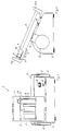
- the mixing device 1 comprises a base 2 within which a driving means in the form of an electric motor is contained. Within the base there are also comprised circuitry for controlling the mixing movement as well as a current source as e.g. a rechargeable battery. Above the base a mixing tray is fastened, which is connected to the drive unit in the base 2 through a driving yoke 4, the substantially horizontal portion of which is fixed to the mixing tray 3. The vertical portions of the driving yoke 4 removably cooperate with slots in driving discs 6 being provided on each side of the base, said discs being connected to the drive unit by means of a drive shaft 5.
- the mixing tray 3 comprises on its upper surface a number of grooves 7 for receiving test tubes 8. The width and the length of the grooves are adjusted so that the mixing device 1 may be used for all test tubes that are available on the market.
- the test tube 8 shown in Figs. 1 and 2 is of vacuum type and consists of a glass tube with a plug 11 in its upper portion. Appropriately filled with blood and anticoagulating agent the tube 8 displays a liquid surface 9 immediately below the plug 11, whereby an air bubble 10 is present between the liquid surface and the plug. As is evident from Fig.
- the mixing tray 3 is comprised with tube stops 12a and 12b at its ends to prevent the tube from gliding off from the mixing tray in its longitudinal direction.
- the grooves 7 end at a portion from the upper tube stop 12a in the figure, whereby a recess 15 is formed, which facilitates putting in and taking out of test tubes from the mixing tray.
- the method of working of the mixing device 1 is as follows. Immediately after that a test tube 8 has been filled with blood from a patient and anticoagulating agent, it is placed on the mixing tray 3 whereafter the sample collector presess the start button 13. The drive unit will then subject the mixing tray 3 to a rocking movement from the position shown in Fig. 2, where the mixing tray is inclined to the left an angle ⁇ to the horizontal plane to a position where the mixing tray is inclined with an angle at the other direction (the angel ⁇ not shown in the figure), which may be different from or equal to ⁇ .
- the angles may be chosen within the area between 15° and 60°, but are preferably between 25° and 45°.
- the rocking frequency may easily be tested concerning e.g.
- the number of oscillations being carried out by the mixing device may also be tested, but is preferably within the area around 8-12.
- the control circuitries of the mixing device are designed in such a way that a start signal leads to the prescribed number of oscillations being carried out thereafter even if the signal is given while the device is already started. In this way it is unnecessary to wait for a completed mixing cycle since there is no risk of sujecting a tube to mixing too long, only by letting it mix for a too short a time.
- the base 2 preferably is comprised with an indicator lamp 14 in the form of e.g. a light diod, for indication of low charging level of the battery in good time before the stand still of the apparatus due to a discharged battery.
- the device may also be provided with a circuit for delivering a light or a sound signal indicating a completed mixing cycle.
- a circuit for delivering a light or a sound signal indicating a completed mixing cycle may be arranged in the circuitry.
- control means delivering e.g. an intermittent light signal when the mixing is not completed.
- the mixing tray 3 may be subjected to a rocking movement of the above mentioned kind by means of any other suitable transmission.
- the removability of the mixing tray can further be achieved in any other suitable manner, e.g. through loosenable connection with respect to the driving yoke, which in itself is permanently fixed to the base.
- the drive unit is started by a test tube 8 being placed in a groove 7 of the mixing tray 3.
- the mixing tray may be provided with any kind of sensing element, which transmits a start signal to the drive unit.
- the test tubes are provided with a detectable, e.g. magnetized, element the presence of which is detected by a detecting unit on the mixing tray, which then sends a start signal to the drive unit.
- Said element may be integral with an identification label or put on the test tube in any other way, e.g. as a piece of magnetic tape.
- the detecting device on the mixing tray may be passive, and thus not consume any energy. If, however, the detecting element is active with a certain current consumption, the device may be provided with control and time circuits aiming to limit the time when the device is in a stand-by position and thereby limit the current consumption.
- a start signal may be given by pressing down of the mixing tray, the driving yoke or corresponding elements in connection with the placing of the test tube on the mixing tray.
Landscapes
- Chemical & Material Sciences (AREA)
- Chemical Kinetics & Catalysis (AREA)
- Investigating Or Analysing Biological Materials (AREA)
- Sampling And Sample Adjustment (AREA)
- Automatic Analysis And Handling Materials Therefor (AREA)
- Mixers With Rotating Receptacles And Mixers With Vibration Mechanisms (AREA)
Abstract
Claims (7)
- Dispositif mélangeur (1) destiné à des éprouvettes pour le sang (8), comprenant un socle (2) avec une unité d'entraînement placée à l'intérieur et, entraîné par celle-ci, un plateau mélangeur (3) destiné à recevoir des éprouvettes, ladite unité d'entraînement étant prévue pour communiquer au plateau mélangeur (3) un mouvement de balancement à une certaine fréquence et selon certains angles d'inclinaison réglés, caractérisé en ce que l'unité d'entraînement est conçue de telle manière qu'au démarrage elle réalise en outre ledit mouvement de balancement avec un nombre déterminé d'oscillations, et que le mouvement de balancement inclut une période de repos à chaque position finale, ladite fréquence, lesdits angles d'inclinaison aux positions finales et la période de repos étant réglés conjointement pour que le processus de mélange prescrit soit réalisé de manière sûre pour chaque éprouvette.
- Dispositif selon la revendication 1, caractérisé en ce que la durée de ladite période de repos est réglable à l'avance et adaptée à ladite fréquence et aux angles d'inclinaison du plateau mélangeur aux positions finales.
- Dispositif selon l'une quelconque des revendications 1 et 2, caractérisé en ce que le plateau mélangeur (3) est fixé à un arceau d'entraînement (4), qui coopère des deux côtés du socle (2) avec des disques d'entraînement (6) pourvus de fentes et s'étendant à partir de l'unité d'entraînement.
- Dispositif selon l'une quelconque des revendications 1 à 3, caractérisé en ce que l'unité d'entraînement est prévue pour réaliser le nombre déterminé d'oscillations après que le signal de départ a été donné, même si elle a déjà démarré.
- Dispositif selon l'une quelconque des revendications 1 à 4, caractérisé en ce qu'un dispositif de détection détecte la mise en place d'une éprouvette (8) sur le plateau mélangeur (3) et délivre ainsi un signal de départ à l'unité d'entraînement.
- Dispositif selon la revendication 5, caractérisé en ce que le dispositif de détection est prévu pour détecter la présence d'un élément détectable par exemple magnétisé qui est fixé à l'éprouvette.
- Dispositif selon l'une quelconque des revendications 1 à 6, caractérisé en ce que le plateau mélangeur (3) est pourvu sur sa surface dirigée vers le haut d'un certain nombre de gorges (7) destinées à recevoir des éprouvettes (8).
Applications Claiming Priority (3)
| Application Number | Priority Date | Filing Date | Title |
|---|---|---|---|
| SE9102736A SE500613C2 (sv) | 1991-09-20 | 1991-09-20 | Blandningsapparat omfattande en för mottagning av provtagningsrör avsedd blandningsplatta, som bibringas en vaggningsrörelse av viss frekvens |
| SE9102736 | 1991-09-20 | ||
| PCT/SE1992/000646 WO1993005874A1 (fr) | 1991-09-20 | 1992-09-18 | Appareil de melange pour eprouvettes |
Publications (2)
| Publication Number | Publication Date |
|---|---|
| EP0604562A1 EP0604562A1 (fr) | 1994-07-06 |
| EP0604562B1 true EP0604562B1 (fr) | 1996-03-20 |
Family
ID=20383786
Family Applications (1)
| Application Number | Title | Priority Date | Filing Date |
|---|---|---|---|
| EP92920545A Expired - Lifetime EP0604562B1 (fr) | 1991-09-20 | 1992-09-18 | Appareil de melange pour eprouvettes |
Country Status (8)
| Country | Link |
|---|---|
| US (1) | US5501521A (fr) |
| EP (1) | EP0604562B1 (fr) |
| JP (1) | JPH06511191A (fr) |
| AU (1) | AU2648992A (fr) |
| DE (1) | DE69209304T2 (fr) |
| ES (1) | ES2085037T3 (fr) |
| SE (1) | SE500613C2 (fr) |
| WO (1) | WO1993005874A1 (fr) |
Families Citing this family (9)
| Publication number | Priority date | Publication date | Assignee | Title |
|---|---|---|---|---|
| US5921477A (en) * | 1996-09-13 | 1999-07-13 | Pioneer Hi-Bred International, Inc. | Apparatus for tissue preparation |
| US7195394B2 (en) * | 2004-07-19 | 2007-03-27 | Vijay Singh | Method for resonant wave mixing in closed containers |
| US8915154B2 (en) | 2011-07-29 | 2014-12-23 | Pioneer Hi Bred International Inc | System and method for preparation of a sample |
| CN103776477A (zh) * | 2014-01-24 | 2014-05-07 | 深圳市华星光电技术有限公司 | 一种摇摆式传感器组件 |
| CN108421470A (zh) * | 2016-01-12 | 2018-08-21 | 梁艳 | 医用旋转式振荡器 |
| FR3090396B1 (fr) * | 2018-12-21 | 2023-03-31 | Seb Sa | Appareil de fabrication, machine à mélange et/ou dispositif de réception pour la fabrication d’une composition à partir d’un mélange de formulations |
| FR3104389B1 (fr) * | 2019-12-12 | 2021-12-10 | Seb Sa | Appareil de fabrication pour la fabrication d’une composition à partir d’un mélange de formulations |
| CN111408300A (zh) * | 2020-04-16 | 2020-07-14 | 河北江驰医疗科技有限公司 | 一种采血管摇匀传输装置 |
| CN114618352B (zh) * | 2022-03-19 | 2023-03-24 | 青岛市中心血站 | 一种采集血液标本用的自动摇摆器 |
Family Cites Families (7)
| Publication number | Priority date | Publication date | Assignee | Title |
|---|---|---|---|---|
| US2834585A (en) * | 1955-12-20 | 1958-05-13 | Oharenko Lubomyra | Retort shaking apparatus |
| US3261594A (en) * | 1964-04-20 | 1966-07-19 | Raymond S Michel | Means for uniformly mixing human blood samples |
| US4673297A (en) * | 1984-07-19 | 1987-06-16 | Cymatics, Inc. | Orbital shaker |
| GB2222997B (en) * | 1988-09-21 | 1992-09-30 | Kubota Ltd | Backhoe implement control system for use in work vehicle |
| JPH0297437U (fr) * | 1989-01-23 | 1990-08-02 | ||
| US4893938A (en) * | 1989-03-08 | 1990-01-16 | Anderson Hilda K | Container shaking device |
| GB2242886B (en) * | 1990-04-11 | 1994-12-07 | Kubota Kk | Backhoe |
-
1991
- 1991-09-20 SE SE9102736A patent/SE500613C2/sv not_active IP Right Cessation
-
1992
- 1992-09-18 EP EP92920545A patent/EP0604562B1/fr not_active Expired - Lifetime
- 1992-09-18 AU AU26489/92A patent/AU2648992A/en not_active Abandoned
- 1992-09-18 US US08/211,248 patent/US5501521A/en not_active Expired - Fee Related
- 1992-09-18 WO PCT/SE1992/000646 patent/WO1993005874A1/fr not_active Ceased
- 1992-09-18 DE DE69209304T patent/DE69209304T2/de not_active Expired - Fee Related
- 1992-09-18 ES ES92920545T patent/ES2085037T3/es not_active Expired - Lifetime
- 1992-09-18 JP JP5505575A patent/JPH06511191A/ja active Pending
Also Published As
| Publication number | Publication date |
|---|---|
| US5501521A (en) | 1996-03-26 |
| JPH06511191A (ja) | 1994-12-15 |
| SE9102736D0 (sv) | 1991-09-20 |
| DE69209304T2 (de) | 1996-09-05 |
| DE69209304D1 (de) | 1996-04-25 |
| SE500613C2 (sv) | 1994-07-25 |
| WO1993005874A1 (fr) | 1993-04-01 |
| ES2085037T3 (es) | 1996-05-16 |
| EP0604562A1 (fr) | 1994-07-06 |
| SE9102736L (sv) | 1993-03-21 |
| AU2648992A (en) | 1993-04-27 |
Similar Documents
| Publication | Publication Date | Title |
|---|---|---|
| EP0604562B1 (fr) | Appareil de melange pour eprouvettes | |
| CN110398596B (zh) | 全自动进样血细胞分析测量方法及装置、对末梢血试管进行混匀操作的方法 | |
| US12174209B2 (en) | Blood sample analyzer with sample agitating structure and blood sample agitating method | |
| US4301412A (en) | Liquid conductivity measuring system and sample cards therefor | |
| US5314825A (en) | Chemical analyzer | |
| JP3677298B2 (ja) | 自動化学分析装置 | |
| EP0434592B1 (fr) | Analyseur et méthode pour tests automatiques sur papier buvard | |
| US20080015623A1 (en) | Electromechanical pricking aid for taking liquid samples | |
| US5624185A (en) | Device for mixing and measuring a quantity of liquid | |
| CA1152772A (fr) | Systeme d'evaluation de la conductivite d'un liquide, et cartes-etalons connexes | |
| EP0516353A1 (fr) | Dispositif de transducteur à ultra-son | |
| EP1010979A1 (fr) | Equipement pour examen clinique | |
| US5680108A (en) | Apparatus and method for monitoring a steeping beverage and for indicating when a desired beverage strength is attained | |
| AU2005203033A1 (en) | Apparatus and method for obtaining rapid creamatocrit and caloric content values of milk | |
| US5680110A (en) | Blood donation monitoring means for monitoring the flow of blood through a receptacle | |
| US3747900A (en) | Blood specimen oscillator | |
| CN209597059U (zh) | 一种医疗检验用自振荡试管 | |
| EP0905506B1 (fr) | Procédé et dispositif de transfert d'un échantillon liquide dans une cuve optique, et polarimètre utilisant ledit dispositif | |
| JPH03115864A (ja) | 液体の流動状態の変化を検出する装置および方法 | |
| US20030029254A1 (en) | Blood analyzer | |
| US6301980B1 (en) | Titration apparatus using a syringe | |
| EP0589528B1 (fr) | Dispositif de mesure du diamètre de tubes à essais | |
| JPH0531566Y2 (fr) | ||
| CN112263733B (zh) | 一种采血信息的监控方法、装置、存储设备及采血仪 | |
| EP1033577A2 (fr) | Support d'échantillon et dispositif pour éliminer un excess d'analyte incorporant un tel support |
Legal Events
| Date | Code | Title | Description |
|---|---|---|---|
| PUAI | Public reference made under article 153(3) epc to a published international application that has entered the european phase |
Free format text: ORIGINAL CODE: 0009012 |
|
| 17P | Request for examination filed |
Effective date: 19940407 |
|
| AK | Designated contracting states |
Kind code of ref document: A1 Designated state(s): BE DE ES FR GB IT NL SE |
|
| RAP1 | Party data changed (applicant data changed or rights of an application transferred) |
Owner name: HJALMARSON, BARBRO HILDA |
|
| RIN1 | Information on inventor provided before grant (corrected) |
Inventor name: HJALMARSON, BARBRO HILDA |
|
| 17Q | First examination report despatched |
Effective date: 19941223 |
|
| GRAA | (expected) grant |
Free format text: ORIGINAL CODE: 0009210 |
|
| AK | Designated contracting states |
Kind code of ref document: B1 Designated state(s): BE DE ES FR GB IT NL SE |
|
| PG25 | Lapsed in a contracting state [announced via postgrant information from national office to epo] |
Ref country code: NL Free format text: LAPSE BECAUSE OF FAILURE TO SUBMIT A TRANSLATION OF THE DESCRIPTION OR TO PAY THE FEE WITHIN THE PRESCRIBED TIME-LIMIT Effective date: 19960320 Ref country code: BE Effective date: 19960320 |
|
| REF | Corresponds to: |
Ref document number: 69209304 Country of ref document: DE Date of ref document: 19960425 |
|
| ET | Fr: translation filed | ||
| REG | Reference to a national code |
Ref country code: ES Ref legal event code: FG2A Ref document number: 2085037 Country of ref document: ES Kind code of ref document: T3 |
|
| ITF | It: translation for a ep patent filed | ||
| PG25 | Lapsed in a contracting state [announced via postgrant information from national office to epo] |
Ref country code: SE Effective date: 19960620 |
|
| NLV1 | Nl: lapsed or annulled due to failure to fulfill the requirements of art. 29p and 29m of the patents act | ||
| PG25 | Lapsed in a contracting state [announced via postgrant information from national office to epo] |
Ref country code: GB Effective date: 19960918 |
|
| PLBE | No opposition filed within time limit |
Free format text: ORIGINAL CODE: 0009261 |
|
| STAA | Information on the status of an ep patent application or granted ep patent |
Free format text: STATUS: NO OPPOSITION FILED WITHIN TIME LIMIT |
|
| 26N | No opposition filed | ||
| GBPC | Gb: european patent ceased through non-payment of renewal fee |
Effective date: 19960918 |
|
| PGFP | Annual fee paid to national office [announced via postgrant information from national office to epo] |
Ref country code: DE Payment date: 20000914 Year of fee payment: 9 |
|
| PGFP | Annual fee paid to national office [announced via postgrant information from national office to epo] |
Ref country code: ES Payment date: 20000920 Year of fee payment: 9 |
|
| PGFP | Annual fee paid to national office [announced via postgrant information from national office to epo] |
Ref country code: FR Payment date: 20000929 Year of fee payment: 9 |
|
| PG25 | Lapsed in a contracting state [announced via postgrant information from national office to epo] |
Ref country code: ES Free format text: LAPSE BECAUSE OF NON-PAYMENT OF DUE FEES Effective date: 20010919 |
|
| PG25 | Lapsed in a contracting state [announced via postgrant information from national office to epo] |
Ref country code: DE Free format text: LAPSE BECAUSE OF NON-PAYMENT OF DUE FEES Effective date: 20020501 |
|
| PG25 | Lapsed in a contracting state [announced via postgrant information from national office to epo] |
Ref country code: FR Free format text: LAPSE BECAUSE OF NON-PAYMENT OF DUE FEES Effective date: 20020531 |
|
| REG | Reference to a national code |
Ref country code: FR Ref legal event code: ST |
|
| REG | Reference to a national code |
Ref country code: ES Ref legal event code: FD2A Effective date: 20021011 |
|
| PG25 | Lapsed in a contracting state [announced via postgrant information from national office to epo] |
Ref country code: IT Free format text: LAPSE BECAUSE OF NON-PAYMENT OF DUE FEES;WARNING: LAPSES OF ITALIAN PATENTS WITH EFFECTIVE DATE BEFORE 2007 MAY HAVE OCCURRED AT ANY TIME BEFORE 2007. THE CORRECT EFFECTIVE DATE MAY BE DIFFERENT FROM THE ONE RECORDED. Effective date: 20050918 |