EP0038054A1 - Dispositif pour la régulation automatique d'un moulin à cylindres, comportant un contrôle d'alimentation de la matière à broyer - Google Patents
Dispositif pour la régulation automatique d'un moulin à cylindres, comportant un contrôle d'alimentation de la matière à broyer Download PDFInfo
- Publication number
- EP0038054A1 EP0038054A1 EP81102782A EP81102782A EP0038054A1 EP 0038054 A1 EP0038054 A1 EP 0038054A1 EP 81102782 A EP81102782 A EP 81102782A EP 81102782 A EP81102782 A EP 81102782A EP 0038054 A1 EP0038054 A1 EP 0038054A1
- Authority
- EP
- European Patent Office
- Prior art keywords
- pneumatic
- control
- control signal
- valve
- roller
- Prior art date
- Legal status (The legal status is an assumption and is not a legal conclusion. Google has not performed a legal analysis and makes no representation as to the accuracy of the status listed.)
- Granted
Links
- 238000000034 method Methods 0.000 claims abstract description 30
- 238000003801 milling Methods 0.000 claims abstract description 19
- 238000000227 grinding Methods 0.000 claims description 61
- 230000008859 change Effects 0.000 claims description 15
- 230000033001 locomotion Effects 0.000 claims description 12
- 230000001960 triggered effect Effects 0.000 claims description 4
- 230000036962 time dependent Effects 0.000 claims 1
- 238000009423 ventilation Methods 0.000 claims 1
- 230000001105 regulatory effect Effects 0.000 abstract description 8
- 238000010276 construction Methods 0.000 abstract description 5
- 239000000523 sample Substances 0.000 description 19
- 230000008569 process Effects 0.000 description 11
- 239000000463 material Substances 0.000 description 8
- 230000008901 benefit Effects 0.000 description 7
- 230000001419 dependent effect Effects 0.000 description 7
- 235000013305 food Nutrition 0.000 description 5
- 230000006835 compression Effects 0.000 description 4
- 238000007906 compression Methods 0.000 description 4
- 230000000694 effects Effects 0.000 description 4
- 239000011521 glass Substances 0.000 description 4
- 230000001276 controlling effect Effects 0.000 description 3
- 238000013461 design Methods 0.000 description 3
- 238000009826 distribution Methods 0.000 description 3
- 238000005516 engineering process Methods 0.000 description 3
- 235000013312 flour Nutrition 0.000 description 3
- 238000005259 measurement Methods 0.000 description 3
- 239000003921 oil Substances 0.000 description 3
- 241000209140 Triticum Species 0.000 description 2
- 235000021307 Triticum Nutrition 0.000 description 2
- 238000006243 chemical reaction Methods 0.000 description 2
- 238000010586 diagram Methods 0.000 description 2
- 238000006073 displacement reaction Methods 0.000 description 2
- 239000012530 fluid Substances 0.000 description 2
- 230000007257 malfunction Effects 0.000 description 2
- 239000000203 mixture Substances 0.000 description 2
- 239000003973 paint Substances 0.000 description 2
- 230000036316 preload Effects 0.000 description 2
- 238000002360 preparation method Methods 0.000 description 2
- 238000005096 rolling process Methods 0.000 description 2
- 230000035939 shock Effects 0.000 description 2
- 230000011664 signaling Effects 0.000 description 2
- 239000000126 substance Substances 0.000 description 2
- 238000012360 testing method Methods 0.000 description 2
- 238000005303 weighing Methods 0.000 description 2
- 241000697035 Heteropriacanthus cruentatus Species 0.000 description 1
- VVQNEPGJFQJSBK-UHFFFAOYSA-N Methyl methacrylate Chemical compound COC(=O)C(C)=C VVQNEPGJFQJSBK-UHFFFAOYSA-N 0.000 description 1
- 229920005372 Plexiglas® Polymers 0.000 description 1
- 206010038743 Restlessness Diseases 0.000 description 1
- 239000006096 absorbing agent Substances 0.000 description 1
- 230000009471 action Effects 0.000 description 1
- 235000008429 bread Nutrition 0.000 description 1
- 238000004140 cleaning Methods 0.000 description 1
- 239000003086 colorant Substances 0.000 description 1
- 238000011109 contamination Methods 0.000 description 1
- 230000006378 damage Effects 0.000 description 1
- 235000013399 edible fruits Nutrition 0.000 description 1
- 230000007613 environmental effect Effects 0.000 description 1
- 238000002474 experimental method Methods 0.000 description 1
- 238000004880 explosion Methods 0.000 description 1
- 230000002349 favourable effect Effects 0.000 description 1
- 238000012423 maintenance Methods 0.000 description 1
- 238000004519 manufacturing process Methods 0.000 description 1
- 239000012528 membrane Substances 0.000 description 1
- 230000003287 optical effect Effects 0.000 description 1
- 235000011837 pasties Nutrition 0.000 description 1
- 239000002994 raw material Substances 0.000 description 1
- 230000004044 response Effects 0.000 description 1
- 238000012216 screening Methods 0.000 description 1
- 238000007873 sieving Methods 0.000 description 1
- 238000012549 training Methods 0.000 description 1
- 238000009827 uniform distribution Methods 0.000 description 1
- 238000003079 width control Methods 0.000 description 1
Images



Classifications
-
- B—PERFORMING OPERATIONS; TRANSPORTING
- B02—CRUSHING, PULVERISING, OR DISINTEGRATING; PREPARATORY TREATMENT OF GRAIN FOR MILLING
- B02C—CRUSHING, PULVERISING, OR DISINTEGRATING IN GENERAL; MILLING GRAIN
- B02C4/00—Crushing or disintegrating by roller mills
- B02C4/28—Details
- B02C4/32—Adjusting, applying pressure to, or controlling the distance between, milling members
- B02C4/38—Adjusting, applying pressure to, or controlling the distance between, milling members in grain mills
-
- B—PERFORMING OPERATIONS; TRANSPORTING
- B02—CRUSHING, PULVERISING, OR DISINTEGRATING; PREPARATORY TREATMENT OF GRAIN FOR MILLING
- B02C—CRUSHING, PULVERISING, OR DISINTEGRATING IN GENERAL; MILLING GRAIN
- B02C4/00—Crushing or disintegrating by roller mills
- B02C4/28—Details
- B02C4/286—Feeding devices
-
- B—PERFORMING OPERATIONS; TRANSPORTING
- B02—CRUSHING, PULVERISING, OR DISINTEGRATING; PREPARATORY TREATMENT OF GRAIN FOR MILLING
- B02C—CRUSHING, PULVERISING, OR DISINTEGRATING IN GENERAL; MILLING GRAIN
- B02C25/00—Control arrangements specially adapted for crushing or disintegrating
-
- B—PERFORMING OPERATIONS; TRANSPORTING
- B02—CRUSHING, PULVERISING, OR DISINTEGRATING; PREPARATORY TREATMENT OF GRAIN FOR MILLING
- B02C—CRUSHING, PULVERISING, OR DISINTEGRATING IN GENERAL; MILLING GRAIN
- B02C4/00—Crushing or disintegrating by roller mills
- B02C4/28—Details
- B02C4/32—Adjusting, applying pressure to, or controlling the distance between, milling members
Definitions
- the invention relates to a method for the automatic control of a mill roller mill provided with a product feed control, in which a mechanical control signal is generated as a function of the control of the setting of the metering slide for the product feed.
- the invention further relates to an automatically controlled milling roller mill provided with a product feed control for carrying out such a method, which has a metering slide for the product feed and a mechanical signal transmitter which is connected to it and acted upon by the product feed.
- Mill grinding or the production of bread, semolina, flour, haze etc. is a special case in grinding technology. Because the quality requirements for the roller mill and its guidance are very high, comparable to, for example, rolling mills for paints or the like.
- a product depot is maintained via two feed rollers, so that the feed rollers can always draw in approximately the same amount of product.
- the supply to the rolling mill is regulated depending on the product status in the depot.
- the milling mill is part of an entire grinding and screening process that is operated fully automatically.
- the grinding preparation is done via one or two lines, which are then led to one to four or even more raw fruit passages.
- the first shot obtained is broken down into plansifters with several fractions, some of which can already be removed from the grinding process as finished products.
- the remaining fractions are continuously fed to a further grinding and sieving process, etc.
- return grinding passages individual outlets from several plan sifters are brought together.
- the amount of flour in each plan sifter varies in shorter and larger intervals.
- the effects of the individual disruptive factors can add up (or even compensate) in the negative sense.
- the performance fluctuations are often less than 10 percent of an average value with the same mixture, but sometimes even in a range of 10 to 30 percent, the upper limit of which can even shift by up to 50 percent from the mean value in the event of an extreme mixture change.
- the grinding rollers In the rear passages as well as in all flat rollers, the grinding rollers must be moved apart if no regrind is fed in, otherwise there is a risk of the grinding rollers running on one another at high relative speeds and at full pressure, and thus the risk of their destruction.
- the task of a product feed control in a milling roller mill is not to ensure constant feed performance, since each roller mill as a link in an entire process chain must be able to fully accept and process incoming product quantities. Rather, the main goal of such a product feed control is to produce a uniform product curtain over the entire length of the grinding rollers.
- DE-C-582 423 describes a combination of electrical and mechanical control means which is also suitable for use by larger control forces, but the structural complexity of which is very considerable, in particular due to the connection of a mechanical and an electrical system.
- Hydraulic controls have also already been used in which large forces can be brought into effect with relatively small hydraulic cylinders, so that the use of mechanical pulse generators is also possible.
- the switching force for the servo control can be very small and the probe construction can thus be kept simple.
- the low switching force offers the advantage that the probes have little resistance to the product flow and can be designed as a self-cleaning construction.
- oil as a foreign substance in the grinding process unnoticed for contamination z. B. can lead the flour; furthermore, the construction effort of such hydraulic constructions is very large and requires an increased constant maintenance. Occasionally, malfunctions were ascertained which were due to changes in the viscosity of the oils used.
- the invention has for its object to improve a method of the type mentioned (with mechanical signal transmitter acted upon by the product supply) in such a way that it is simple and easy to carry out control operations with great effort ge is suitable and, with very good control effects, is particularly reliable in terms of operation and functionality.
- a suitable device for carrying out such a method is also to be found.
- a mechanical control signal derived from the feed product stream is first converted into a pneumatic control signal, which is then passed on via pneumatic servo means to the power-dependent elements of the roller mill, which in turn then apply the desired adjusting forces and the necessary control functions via pneumatic servo support To run.
- the mechanical control signal is advantageously converted into a digi tales pneumatic control signal converted.
- the contact pressure between the grinding rollers can also preferably be controlled with the pneumatic control signal in the method according to the invention.
- a further advantageous embodiment of the invention is that every change in the mechanical control signal is immediately converted into an analog change in the pneumatic control signal, but the changed pneumatic control signal is then, depending on the time, returned to its initial value before the change occurred, with this The process is of course immediately interrupted and initiated again as soon as a further change in the mechanical control signal occurs.
- This enables a time-delayed follow-up of the zero point for the signal change of the pneumatic control signal, which, when using suitable pneumatic servomotors for the actuation of the power-dependent elements (metering gap slide, grinding roller engagement and disengagement), creates favorable conditions for setting a stable equilibrium position, from which then another control impulse can go out. This setting of calm equilibrium positions ultimately results in a very quiet feed to the milling wheat.
- the pneumatic control signal is gradually (digitally) returned as it drops towards the initial value, which means that the sensor of the mechanical feed control signals can be derived by superimposing a partly digital, partly analog pneumatic signal.
- the digital step is then preferably used in that the digital part is used directly for an adjustment function, while the analog part is used to hold a certain position (equilibrium position).
- the method according to the invention allows e.g. B. in the case of a relatively constant product supply also to keep the product level in the dining room constant, but also to smooth it somewhat with strong fluctuations in output due to the product feed control used. Short-term shock loads in the product feed are always passed on with a slight delay due to the system elasticities, even if a time delay, for example during the conversion, is not directly taken into account.
- overrun zero point adjustment
- a first rough setting of the system is made aims, but the fine adjustment is achieved by the constant effect of an analog control signal converted into a pneumatic one.
- the automatically controlled milling mill roll mill provided with a product feed control, on which the method according to the invention can be carried out, is provided with a metering slide for the product feed and with a mechanical signal transmitter connected to it and acted upon by the product feed.
- the mechanical signal transmitter is designed to actuate a pneumatic control valve, the output of which is connected to the input of a servo device for adjusting the metering slide and / or for disengaging and engaging the grinding rollers.
- the pneumatic control valve is operatively connected to the servo device in such a way that it follows every movement of the transmitter element with a delay.
- a particularly simple and effective, advantageous embodiment can be achieved in that the pneumatic control valve can be switched into a switch-on, a switch-off and a zero position between the switch-on and the switch-off position by means of the transmitter element, it being part of the structural unit in each of these three positions can linger.
- the servo device has a pneumatic cylinder with piston and piston rod, which on the one hand attached to the housing of the roller mill and the piston rod to the other directly connected to adjusting elements for the metering slide or the devices for grinding roller engagement and disengagement, the piston rod on one side with a (preferably constant) feed force, which acts as a corresponding feed air pressure or can be applied as a spring force, and the control pressure (outlet pressure) of the pneumatic valve is acted upon on its other side in such a way that when the valve is set to zero, the control-side compressed air is trapped and the last control pressure is maintained.
- This configuration in which the servo device non-positively engages the adjusting means for performance-dependent elements of the roller mill, results in a kind of closed mechanical / pneumatic weighing or taring system from the control device together with the transmitter of the feed control signal.
- a lever arm which is articulated at one end to the frame of the roller mill is provided, which is connected at its free end to the housing of the pneumatic valve and on which the piston rod is directly connected
- Servo device preferably also links for adjusting the metering slide (metering gap) and / or the speed of the feed roller, are attached.
- the servo device forms together a functional unit with the lever arm articulated on one side of the roller mill, the transmitter of the feed control signal controlling the pneumatic control valve attached to the outer end of the lever arm and the pneumatic cylinder acting directly on the lever arm.
- the invention makes it possible to regulate the feed power with little moving parts via the servo device by adjusting the metering slide and / or a feed roller speed.
- an embodiment for a milling mill roller mill for food control alternatively or simultaneously by means of a metering slide on the one hand and a feed roller speed on the other hand could be achieved, which, with good functionality, is characterized by a surprisingly low structural outlay.
- an adjustment of the metering slide can bring optimal results, in other cases when e.g. B. there is a larger proportion of bran (for example in the first passages), however, with the sole adjustment of the metering slide no satisfactory results can be achieved.
- the roller mill according to the invention now offers the possibility, in such cases, of using the servo device in a very simple manner to apply a sufficiently large force also for regulating the speed of the food roller.
- the control signal which is transformed as a pneumatic signal, can now advantageously be used to control the engagement and disengagement of the grinding rollers by applying the control pressure of the pneumatic control valve to a second valve. which in turn controls the engagement and disengagement of the grinding rollers.
- the control pressure of the second valve can also be used to visually indicate the engagement or disengagement of the grinding rollers.
- the pneumatic control valve is designed as a diaphragm valve which is switched by a tappet or roller lever which has a vent opening.
- the structural design of the roller mill according to the invention is surprisingly simple; Tests under practical conditions have shown that the roller mill according to the invention, when used in practice, achieves the object on which the invention is based: task with the best functional reliability.
- Experiments showed that in an investigated case in which the product performance of the roller mill was uniform, the product level in the dining area above the metering rollers also remained constant.
- the metering performance was optimally adapted to the fluctuations in performance by the solution according to the invention, but a strong compensation could also be achieved at the same time.
- FIG 1 is a mill roller mill in double Execution, that is shown with two pairs of grinding rollers 1, 1 'or 2, 2', in which the grinding rollers are widely supported in a stand, the entire roller mill being closed to the outside with a casing 4.
- the regrind is fed through a feed cylinder 5, which is usually made of plexiglass, to an expanded dining room 6, at the lower end of which there is a distribution screw 7 and a food roller 8. Together with a metering slide 9, this feed roller forms the mechanical part of a metering unit.
- a trimelle 10 for ground material is provided below the grinding rollers 1, 1 ', 2, 2'.
- the casing 4 there is also a service door 11 for the feed side of the grinding rollers 1, 1 ', 2, 2' and a control door 12 through which the quality and quality of the ground material can be monitored.
- a probe 13 is arranged in or above the dining area 6 and can move a sensor 15 about an axis of rotation 14.
- the movement of the encoder 15 is influenced on the one hand by the amount of product and on the other hand also by the kinetic energy of the flowing product mass and by a return spring 16. Since the displacement / force behavior of the return spring 16 can be selected or is already known, the encoder 15 therefore has a mechanical signal analogous to the product feed power (as in the case of a mechanical balance).
- the encoder 15 is in direct operative connection with a pneumatic valve 17 or a roller lever and a tappet of this valve.
- the mechanical signal of the encoder 15 is converted into a pneumatic control signal in the pneumatic valve 17, where in which the compressed air supplied to the pneumatic valve 17 is converted by means of the pneumatic valve into a pressure control signal analogous to the product feed power.
- This signal referred to as the "feed control signal” represents the output signal for controlling and regulating individual (or preferably several): ' power-dependent elements of the roller mill.
- the feed control signal can be used for the actual feed control as well as for adjusting the speed of the feed rollers 8 or to adjust a metering gap by adjusting the metering slide 9.
- the feed control signal can also be evaluated by an automatic setting device 19 to adapt the grinding roller setting.
- This setting device 19 can be evaluated.
- This setting device can be combined with a hand setting wheel 20 or, in the case of a further automatic expansion, with a corresponding computer - controlled remote control, as described, for example, in CH-A-418 1791.
- control signal which is present as a pressure signal
- the control signal can be evaluated individually for each individual function, but very particularly with regard to a combination of several control and regulating functions.
- the focus here is on the one hand on the combined regulation of the feed power and the roller engagement and disengagement on the other hand, both of which can be carried out via a common pneumatic / mechanical servo circuit.
- FIG. 2 the individual structural elements of the feed control are shown schematically.
- the left half of the figure shows the zone of the dining area of the mill roller mill according to FIG. 1 'on average, while the right half of the figure shows schematically the assignment of the feed roller to the grinding rollers.
- the ground material is placed in a dining area 31 via a glass cylinder 30, which is closed at the bottom by a metering slide 32 and a feed roller 33.
- a metering gap “Sp" is formed between the feed roller 33 and the metering slide 32.
- the feed roller 33 is directly downstream of a distribution roller 34, which ensures a uniform distribution of the products over the entire length of the roller.
- a probe 35 is articulated to a carrier 36 via a corresponding weighing beam. This carrier, together with the probe 35, can perform a tilting movement about the axis 37, a tension spring 38 counteracting the weight, such as the impulse of the ground material, which loads the carrier 36 in the clockwise direction.
- a mechanically generated control signal is also analogous to FIG. 1 dispensed via the (shown in the figure on the right) arm piece 36 'of the carrier 36 as a transmitter on a pneumatic valve 39 which, for. B. can be constructed as shown in Figure 8.
- the pneumatic valve 39 converts the mechanical control signal into an analog pneumatic pressure signal, which is given via a control line 40 to one side of a pneumatic cylinder 41 as an effective control or pressure force.
- a pressure spring 44 acts on a piston 42 or an associated piston rod 43 arranged in the pneumatic cylinder 41 and the pressure on the other side according to the analog control signal of the pneumatic valve 39.
- the piston rod 43 is articulatedly connected to the metering slide 32, that this is adjusted by the piston rod 43 about a pivot point 45 and thereby the metering gap "Sp" can be set.
- a closed servo feed control circuit is therefore formed above the elements mentioned, in particular the pneumatic valve 39, the pneumatic cylinder 42 as a servo device and the metering slide 32 on the one hand, and the force play of the grinding material probe, on the other hand, for which no additional external energy is required apart from the compressed air.
- the functioning of the device is as follows: is the product level in the dining area 31 below the probe z. B. at the height "A”, no force is applied to the regrind. the probe 35 delivered more.
- the tension spring 38 pulls down the arm piece 36 'or the mechanical transmitter, the plunger 46 of the pneumatic
- the valve 39 is relieved and there is no pressure in the control line 40.
- the force of the compression spring presses the metering regulator 32 against the feed roller or against a stop (not shown), so that the metering gap "Sp" is set to the value 0 or almost 0. Now grist through the glass cylinder. 30 fed to the roller mill, there is a momentum and weight force on the probe 35.
- the encoder pushes the plunger 46 in proportion to the product output supplied, whereby a corresponding pressure signal is formed in the pneumatic valve 39, which in turn via the servo cylinder 41, the metering gap "Sp" enlarged.
- the metering slide 32 is opened or moved until equilibrium is established between the amount of product fed in via the dining area 31 and the metering rate subtracted below. In the case of equilibrium, the regrind level in the dining room remains approximately constant.
- a branch line 41 goes from the control line 40 directly to a second servo cylinder 50 which is fastened on the axis of a vario disc 51.
- One of the grinding rollers 1, 1 ', 2, 2' which is driven by a main motor (not shown), drives the feed roller via a vario belt drive 52. If there is now no pressure on the control line 41, a spring 53 displaces the movable half 51 of the pulley against the fixed half 51 ′′. The distance between the two disc halves is smaller and the A wedge-shaped drive belt is pressed outwards. At the same time, the feed roller speed slows down by increasing the effective diameter of the driven pulley.
- the pneumatic valve 39 acts, as in FIG. 8 on an enlarged scale, like a displacement-pressure converter: a displacement is converted into an analog pneumatic signal.
- the mode of action is as follows:
- the compression spring 62 When the plunger 61 is pushed in, the compression spring 62 is tensioned, the spring shoe 63 presses the ball onto the seat of the pilot nozzle 64, after which (fed by supply air 60) the pressure in the chamber 65 increases proportionally with the spring force or the spring travel.
- the membrane of the attached power amplifier is pressed down and opens the ball valve 67 until an equal pressure has built up in the chamber 66.
- the pilot nozzle 64 opens, as a result of which the pressure in the chamber 65 is reduced.
- the falling pressure in the chamber 65 now causes the diaphragm to be pushed up by the pressure in the chamber 66 and the ball valve 68 is opened.
- the product feed control is shown schematically in FIG. 3: in the left half of the figure, the feed area 70 is shown, which is closed at the bottom by a distribution roller 71, a feed roller 72 and a metering slide 73.
- a probe 74 is arranged in the dining area 70 and is supported on a pivot pin 76 by a support 75.
- the carrier 75 has a transmitter 77 which is operatively connected on the one hand to a tension spring 78 and on the other hand to a roller lever 79 of a pneumatic valve 80.
- the pneumatic valve 80 is connected on the input side to a compressed air line 81; a control line 82 leads from the pneumatic valve 80 to a servo cylinder 83 to act on a piston 84 located therein on one side thereof.
- a piston rod 85 is provided, which is fastened at the end with a hinge pin 86 to a lever arm 87, which in turn is articulated on the fixed frame structure 89 about a swivel joint 88.
- the pneumatic valve is fastened to the other end of the lever arm 87 and follows the movement of the piston rod 85 or the lever arm 87 in accordance with the lever laws.
- a metering slide 90 is also non-positively fastened to the latter via a connecting bracket 91 or via planks 92 and 93 .
- the metering slide 90 can be tilted about a pivot bearing 94, a metering gap “Sp” being established between it and the feed roller 72, depending on its current position.
- the whole system is fed by a pressure supply 95.
- the compressed air for the control side can additionally Lich interrupted by a hand switch 98, for example to perform service work.
- the system supply is kept constantly at a constant pressure by the supply mentioned, which pressure (for example, at a value of 6 bar) is delivered via a line 99 as a counterpressure to the side of the piston 84 which is away from the control pressure.
- a spring 100 or both can also be used together.
- the use of a spring 100 has the advantage that the metering slide closes securely if the compressed air fails.
- FIG. 4 shows the pressure curve of the control signal, as can be determined in the control line 82 using a pressure recorder.
- the values correspond to the measurement on a roller mill, a B passage.
- the pressure is remarkably stable and was only briefly interrupted (at about 29 seconds) by a short pressure increase.
- the essentially horizontal course of the curve shows that very brief power variations are passed on in the control signal.
- the entire control circuit was artificially interrupted by manual disengagement of the grinding rollers 1, 1 ', as a result of which the control signal immediately drops to zero.
- the rapid response of the control to a corresponding malfunction is very advantageous. However, it is particularly important to start the control after the grinding rollers are engaged.
- the control signal runs out for about 1 second.
- the signal starts again occurs almost without delay and the signal, which is particularly interesting from a control point of view, immediately changes to an approximately medium value, then oscillates around this value for about 10 seconds and then immediately changes back to a stable control behavior.
- the quick reaction to the change which takes place with almost no oversteer and no rocking.
- FIG. 4 shows constantly recurring constant control periods of 5 to 10 seconds, all of which lie within a relatively narrow control range. This is very important for the grinding rollers and for the roller bearings, since the feed control device prevents vibrations from fluctuating due to constantly changing grinding forces.
- FIG. 5 shows the control signal for a C passage (ie for a rear passage) in which the amount of product fed to the roller mill almost does not vary over shorter and longer periods. This case is particularly easy to control in terms of control technology. About 5 seconds after the start of the measurement, the product supply was briefly disrupted, which immediately triggered a corresponding drop in the control signal. In terms of control technology, the curve curve that follows is almost a kind of "ideal curve". Here too, the grinding rollers were briefly removed by hand after about 115 seconds and then immediately reinserted without delay. The diagram shown shows astonishingly that after a very slight oversteer Already after about 1 to 2 seconds the same control value as before the artificial disturbance is restored and the original curve continues.
- an encoder 111 is actuated by a probe 110.
- a tension spring 112 acts on the transmitter 111, which, if no product is fed to the roller mill, lifts it from the switch contact 113 of a pneumatic valve 114.
- a control line 115 leads from this pneumatic valve 114 to an booster valve 116.
- the pneumatic valve 114 converts the mechanical control signal of the transmitter 111 into a pneumatic pressure signal.
- a pneumatic control signal is formed in proportion to the incoming feed power to the probe 110.
- the booster valve 116 is set such that it immediately releases the full network pressure (eg 6 bar) from the pressure line 117 into a pneumatic cylinder 118 at a certain pressure value of the pneumatic control signal of the control line 115. If the set threshold value of the pressure signal for the booster valve 116 has not yet been reached, the left surface of the piston 120, which is displaceably arranged within the pneumatic cylinder 118, remains depressurized. In contrast, the full network pressure acts on its right surface, so that the piston 120 remains in the disengaged position. However, if the pressure in the control line 115 exceeds the set threshold value of, for example, 2 bar, then the full network pressure is applied to the left piston surface, causing the piston to extend. By means of a central control valve 96, all can then Rollers Wa 1 , Wa 2 .... can be disengaged using the quick breather 97.
- the full network pressure eg 6 bar
- the piston 120 is coupled via a piston rod 121 to the movable roller 1, 2 or the corresponding roller bearing, so that the movement described is used directly by the control signal to engage or disengage the grinding rollers.
- the compressed air supply can be designed according to that according to FIG. 3 (matching parts are therefore provided with the same reference numbers).
- control function for the feed power is very different from the function of the roller engagement and disengagement.
- the regulation of the feed rate should preferably be carried out gently, whereas the engagement and disengagement of the grinding rollers should take place suddenly (but without the rollers hitting each other).
- a point "S-off” and “S-on” are shown at the pressure level 2 bar as a threshold value for switching the valve 116 for engaging or disengaging the grinding rollers.
- the switching point for valve 116 is deliberately chosen to be significantly lower than the normal working range for the feed power.
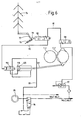
- FIG. 7 shows an embodiment in which the one essentially shown in FIG. 3 is shown. Feed regulation is combined with a roller engagement and disengagement according to FIG. 6.
- FIG. 1 the embodiment for a typical mill roller mill with a double design for the actual grinding unit is shown in FIG.
- the servo cylinder for the roller engagement and disengagement is provided at each roller end, that is to say four times in total.
- the grinding gap of the grinding rollers 1, 1 ', 2, 2' is preselected using a handwheel in accordance with the material to be ground. If no regrind is being fed in above the feed cylinder 5, the probe 13 or 74 is moved via a tension spring 16 or ' 78 pushed up. The transmitter 15 or 77 does not touch the switch contact 79 of the pneumatic valve 17 or 80, so that no pressure is built up in the control line 82. -The spring 100 or the pressure from line 99 (or both, depending on the choice of system) press the lever arm 87 counterclockwise and thus the metering slide 9 or 73 in a closed position. The dosing gap "Sp" is closed, so that no product is metered onto the grinding rollers 1, 1 ', 2, 2'. If there is no control signal in the control line 82 or 115, there is also no control pressure at the booster valve 116, which is why the grinding rollers 1, 1 ', 2, 2' are in the disengaged position via the cylinders 118.
- the probe 13 or 74 is in motion with the transmitter 15 or 77, ie the switching contact 79 is pressed fully onto the pneumatic valve 17 or 80 in one go.
- the transmitter especially when using a very sensitive diaphragm valve for the pneumatic valve 80, releases the maximum control pressure in the control line 82 with the smallest movements.
- the piston rod 85 with the lever 87 and the pneumatic valve 80 in a period of Hundredths or tenths of a second are set in motion, whereby the directly connected metering slide begins to open and product is fed onto the grinding rollers.
- Both the cylinder 118 and the cylinder 83 are designed as pneumatic servo cylinders, as a result of which the workforce is generated quickly but not suddenly.
- the air in the cylinder forms a kind of "shock absorber". It has been shown that a suitable choice of the tension and compression springs of the cross-sections in the pneumatic lines and corresponding preloads of the springs can achieve a perfect synchronization of the control or regulating functions with regard to the machine elements concerned. This applies to both the inlet and outlet.
- the lever arm 87 executes a small swiveling movement clockwise when the product feed is inserted as the first phase. Simultaneously with this, the switching contact 79 also runs away from the transmitter 77. The tension spring 78 tensions in proportion to the distance of the transmitter 77. If only a small amount of product is fed in via the glass cylinder, an equilibrium is very quickly established between the regrind forces on the probe 13 or 74, in which the feed segment 73, the lever arm 87 and the pneumatic valve remains in its position.
- the transmitter 77 and the switching contact 79 which can be inserted into the pneumatic valve 80 via a spring, are in constant mutual operative connection, smallest movements occur, which, however, which is a significant advantage, no longer have a direct influence on the converted pneumatic control signal.
- the pneumatic valve remains in a so-called zero position, in which all inputs and outputs are closed.
- the pressure value of the pneumatic control signal generated in the first phase remains unchanged and the piston 84 remains rigidly clamped with relatively large forces on both piston sides due to the stable pressure conditions.
- the metering slide remains in its position.
- the transmitter 77 or 15 continues to move in the direction of the switching contact 79 or on the pneumatic valve 89, the latter following the transmitter 77 and again emitting a corresponding control signal as an increased pressure value into the control line 82 at a set threshold value.
- a pneumatic control signal is predefined or triggered approximately according to FIG. 4 or FIG. 5.
- a stable balance can be established via a uniform signal curve, such as this can be seen from Figure 5.
- control pressure in line 119 can be used for the optical display of the respective position of the rollers. With the compressed air z. B. a colored buckle behind a glass eye 120 so that the engagement or disengagement of the grinding rollers by appropriate colors, for. B. red and green, is displayed.
- the pneumatic control signal in the control line 82 can be used to set the grinding rollers independently of the power. For example, the grinding gap can be kept constant when the metering capacity is increased by increasing the grinding pressure, or can also be reduced or enlarged.
- the corresponding gap width control device 19 may be made directly from a pneumatic cylinder or other suitable mechanical or electrical means, which at the same time to a remote control (such as a computer or process computer) - to be connected, which then specifies a base value for the respective Mahlaufgabe, which is adjusted depending on the power by the pneumatic control signal of the instantaneous power in the roller mill.
- a remote control such as a computer or process computer
- the pressure between grinding rollers can also be controlled as a function of the feed power or by means of the pneumatic control signal.
- the pneumatic control signal can simultaneously regulate both the feed power and the engagement and disengagement of the grinding rollers.
Landscapes
- Food Science & Technology (AREA)
- Engineering & Computer Science (AREA)
- Crushing And Grinding (AREA)
- Disintegrating Or Milling (AREA)
- Finish Polishing, Edge Sharpening, And Grinding By Specific Grinding Devices (AREA)
- Fluid-Pressure Circuits (AREA)
- Sampling And Sample Adjustment (AREA)
- Devices For Medical Bathing And Washing (AREA)
- Percussion Or Vibration Massage (AREA)
- Adjustment And Processing Of Grains (AREA)
- Steroid Compounds (AREA)
- Ticket-Dispensing Machines (AREA)
- Control Of Metal Rolling (AREA)
Priority Applications (1)
| Application Number | Priority Date | Filing Date | Title |
|---|---|---|---|
| AT81102782T ATE16570T1 (de) | 1980-04-11 | 1981-04-10 | Einrichtung zum automatischen steuern eines mit einer produkt-speiseregelung versehenen muellerei- walzenstuhles. |
Applications Claiming Priority (4)
| Application Number | Priority Date | Filing Date | Title |
|---|---|---|---|
| CH2796/80 | 1980-04-11 | ||
| CH2796/80A CH655251A5 (de) | 1980-04-11 | 1980-04-11 | Muellerei-walzenstuhl mit einer produkt-speiseregelvorrichtung sowie verfahren zum betrieb des muellerei-walzenstuhles. |
| DE3022564 | 1980-06-16 | ||
| DE3022564A DE3022564C2 (de) | 1980-04-11 | 1980-06-16 | Produkt-Speiseregelung für Müllerei-Walzenstuhl |
Publications (3)
| Publication Number | Publication Date |
|---|---|
| EP0038054A1 true EP0038054A1 (fr) | 1981-10-21 |
| EP0038054B1 EP0038054B1 (fr) | 1985-11-21 |
| EP0038054B2 EP0038054B2 (fr) | 1990-01-10 |
Family
ID=4241774
Family Applications (1)
| Application Number | Title | Priority Date | Filing Date |
|---|---|---|---|
| EP81102782A Expired - Lifetime EP0038054B2 (fr) | 1980-04-11 | 1981-04-10 | Dispositif pour la régulation automatique d'un moulin à cylindres, comportant un contrôle d'alimentation de la matière à broyer |
Country Status (19)
| Country | Link |
|---|---|
| US (1) | US4442980A (fr) |
| EP (1) | EP0038054B2 (fr) |
| JP (1) | JPS6112745B2 (fr) |
| KR (1) | KR850000774B1 (fr) |
| AT (1) | ATE16570T1 (fr) |
| BR (1) | BR8108439A (fr) |
| CH (1) | CH655251A5 (fr) |
| CS (1) | CS256368B2 (fr) |
| DD (1) | DD158209A5 (fr) |
| DE (1) | DE3022564C2 (fr) |
| ES (1) | ES501239A0 (fr) |
| HU (1) | HU189976B (fr) |
| LT (1) | LT2539B (fr) |
| LV (1) | LV5593A3 (fr) |
| MX (1) | MX156160A (fr) |
| PL (1) | PL140702B1 (fr) |
| SU (1) | SU1173937A3 (fr) |
| UA (1) | UA6000A1 (fr) |
| WO (2) | WO1984004469A1 (fr) |
Cited By (3)
| Publication number | Priority date | Publication date | Assignee | Title |
|---|---|---|---|---|
| WO1998058738A1 (fr) * | 1997-06-23 | 1998-12-30 | Bühler AG | Systeme de detecteurs pour operations d'alimentation |
| RU2183507C2 (ru) * | 1996-12-13 | 2002-06-20 | Бюлер Аг | Вальцовый станок для получения продуктов размола зерна и питающий модуль для вальцового станка |
| CN108325614A (zh) * | 2018-05-04 | 2018-07-27 | 王小龙 | 齿辊可调的破碎机 |
Families Citing this family (30)
| Publication number | Priority date | Publication date | Assignee | Title |
|---|---|---|---|---|
| CH658202A5 (de) * | 1982-03-16 | 1986-10-31 | Budapesti Elelmiszeripari Gepg | Mahlanlage zum vermahlen von getreide und aehnlichen produkten. |
| IT1160480B (it) * | 1983-02-25 | 1987-03-11 | Sangati Spa | Dispositivo per la regolazione automatica della alimentazione del prodotto in un laminatoio di macinazione per cereali |
| IT1161106B (it) * | 1983-03-10 | 1987-03-11 | Sangati Spa | Dispositivo per la regolazione automatica della alimentazione del prodotto in un laminatoio di macinazione per cereali |
| US4591054A (en) * | 1984-07-23 | 1986-05-27 | Blossom Carolyn S | Combination purse-coupon organizer device, methods of constructing and utilizing same |
| JPS6137629A (ja) * | 1984-07-30 | 1986-02-22 | Asahi Breweries Ltd | 軽粉粒体処理装置における詰り防止方法及びその装置 |
| FR2576223A1 (fr) * | 1985-01-24 | 1986-07-25 | Schneider Jaquet Cie Ets | Dispositif de reglage applicable a l'appareil de distribution quantitatif pour cylindres de broyage et de reduction |
| US5201470A (en) * | 1987-10-06 | 1993-04-13 | Buehler Ag | Method for the production of milled grain products and roller mill |
| GB2214106B (en) * | 1987-12-24 | 1991-06-26 | Smidth & Co As F L | Vertical roller mill |
| CH682809A5 (de) * | 1990-12-12 | 1993-11-30 | Buehler Ag | Produktspeiseautomatik, Verfahren zur Steuerung der Vermahlung eines Müllereiwalzenstuhles. |
| DE4314413C2 (de) * | 1993-05-04 | 1996-05-09 | Heidenauer Maschf Gmbh | Verfahren zum Beschicken einer Walzenreibmaschine |
| US20070051836A1 (en) * | 2005-09-07 | 2007-03-08 | The Coca-Cola Company | Bi-modal roller grinder |
| ITMI20072248A1 (it) * | 2007-11-29 | 2009-05-30 | Ocrim Spa | Apparecchiatura e metodo di controllo di laminatoi a rulli negli impianti per la macinazione di prodotti alimentari |
| RU2449835C1 (ru) * | 2010-08-24 | 2012-05-10 | Государственное образовательное учреждение высшего профессионального образования "Сибирская государственная автомобильно-дорожная академия (СибАДИ)" | Валковая дробилка |
| RU2603727C2 (ru) * | 2011-05-12 | 2016-11-27 | Бюлер Аг | Устройство и способ измельчения частиц в текучем материале |
| DE102012106554A1 (de) * | 2012-07-19 | 2014-05-15 | Thyssenkrupp Resource Technologies Gmbh | Verfahren und Anlage zur Zerkleinerung von Mahlgut mit einer Rollenmühle |
| JP6238044B2 (ja) * | 2013-04-23 | 2017-11-29 | 株式会社サタケ | 製粉用ロール機におけるストックレベル検出器 |
| CN103341392A (zh) * | 2013-06-06 | 2013-10-09 | 吉林市新大科机电技术有限责任公司 | 一种轮式连续自动加料装置 |
| BR102015021252B1 (pt) * | 2015-09-01 | 2019-10-15 | Vale S/A | Prensa de rolos para minérios e método para obtenção de máxima eficiência de uma prensa de rolos |
| CN105170301B (zh) * | 2015-10-27 | 2017-09-01 | 张荣斌 | 一种八辊式破碎机的自动控制方法 |
| CN106732926A (zh) * | 2017-01-23 | 2017-05-31 | 温州市朴红农业科技有限公司 | 一种红薯磨粉机 |
| WO2019093958A1 (fr) * | 2017-11-10 | 2019-05-16 | Metso Sweden Ab | Kit de remontage de distributeur de déviation pour un broyeur à rouleaux, broyeur à rouleaux et procédé de montage d'un tel kit |
| SE541957C2 (en) * | 2017-11-10 | 2020-01-14 | Metso Sweden Ab | A deflection distributor refitting kit, a method for mounting and a roller crusher comprising such kit |
| WO2019093956A1 (fr) * | 2017-11-10 | 2019-05-16 | Metso Sweden Ab | Kit de remontage de distributeur de déviation pour un broyeur à rouleaux, broyeur à rouleaux et procédé de montage d'un tel kit |
| US11246330B2 (en) * | 2018-01-26 | 2022-02-15 | Chris Deakin | System and method for flaking |
| CN112021379A (zh) * | 2018-07-19 | 2020-12-04 | 杨亚洲 | 一种猪头肉用绞碎机构及使用方法 |
| CA3139077A1 (fr) | 2019-05-09 | 2020-11-12 | Metso Outotec USA Inc. | Dispositif de broyage |
| PE20212350A1 (es) | 2019-05-09 | 2021-12-16 | Metso Outotec Usa Inc | Chancador de rodillos |
| AU2019444627B2 (en) * | 2019-05-09 | 2025-09-04 | Metso Usa Inc. | Crushing device |
| DE102020104526B4 (de) * | 2020-02-20 | 2024-03-28 | Maschinenfabrik Köppern Gmbh & Co. Kg | Hochdruck-Walzenpresse |
| CN118320958B (zh) * | 2024-02-20 | 2024-10-11 | 嘉兴市宏宇新材料股份有限公司 | 一种玻璃纤维短切毡废丝回收再利用处理装置及使用方法 |
Citations (6)
| Publication number | Priority date | Publication date | Assignee | Title |
|---|---|---|---|---|
| DE582423C (de) * | 1933-08-15 | Schneider Jaquet & Cie Sa | Speisevorrichtung fuer Walzenstuehle | |
| CH275417A (de) * | 1949-04-14 | 1951-05-31 | Buehler Ag Geb | Schalt- und Regelvorrichtung für Walzenstühle. |
| DE817069C (de) * | 1949-04-14 | 1951-10-15 | Buehler Ag Geb | Regeleinrichtung fuer Walzenstuhlspeisung |
| DE859102C (de) * | 1949-12-01 | 1952-12-11 | Miag Vertriebs Gmbh | Regelvorrichtung fuer Walzenstuehle mit Servomotor |
| GB751464A (en) * | 1954-10-14 | 1956-06-27 | Allis Chalmers Mfg Co | Roller mill feed and roll positioning control apparatus |
| US2984423A (en) * | 1956-08-23 | 1961-05-16 | Buehler Ag Geb | Control device for roller mill |
Family Cites Families (8)
| Publication number | Priority date | Publication date | Assignee | Title |
|---|---|---|---|---|
| CH306619A (de) * | 1942-12-10 | 1955-04-30 | Miag Muehlenbau & Ind Gmbh | Regelvorrichtung für den Mahlgutzulauf bei Walzenstühlen. |
| CH282359A (de) * | 1949-04-14 | 1952-04-30 | Buehler Ag Geb | Selbsttätige Regelungseinrichtung für Walzenstühle. |
| GB698085A (en) * | 1949-04-14 | 1953-10-07 | Buehler Ag Geb | Improved regulator for roller-mills |
| CH286841A (de) * | 1950-12-09 | 1952-11-15 | Buehler Ag Geb | Reguliervorrichtung für die Segmentspeisung eines Walzenstuhles. |
| CH418791A (de) * | 1964-07-03 | 1966-08-15 | Buehler Ag Geb | Müllereiwalzenstuhl |
| US3468488A (en) * | 1965-11-30 | 1969-09-23 | Buehler Ag Geb | Automatic control of feed material in a comminuting mill |
| CH508421A (de) * | 1969-05-09 | 1971-06-15 | Buehler Ag Geb | Verfahren zum Verreiben von pastösem Reibgut und Vorrichtung zur Durchführung des Verfahrens |
| DE2856546A1 (de) * | 1978-12-28 | 1980-07-10 | Rickmeier Pumpen | Druckeinstellventil fuer einen hydraulikkreis |
-
1980
- 1980-04-11 CH CH2796/80A patent/CH655251A5/de not_active IP Right Cessation
- 1980-06-16 DE DE3022564A patent/DE3022564C2/de not_active Expired
- 1980-12-05 WO PCT/CH1980/000151 patent/WO1984004469A1/fr not_active Ceased
- 1980-12-05 US US06/321,165 patent/US4442980A/en not_active Expired - Lifetime
-
1981
- 1981-04-08 CS CS812637A patent/CS256368B2/cs unknown
- 1981-04-10 HU HU811453A patent/HU189976B/hu unknown
- 1981-04-10 BR BR8108439A patent/BR8108439A/pt unknown
- 1981-04-10 EP EP81102782A patent/EP0038054B2/fr not_active Expired - Lifetime
- 1981-04-10 UA UA3362004A patent/UA6000A1/uk unknown
- 1981-04-10 AT AT81102782T patent/ATE16570T1/de not_active IP Right Cessation
- 1981-04-10 WO PCT/EP1981/000028 patent/WO1981002852A1/fr not_active Ceased
- 1981-04-10 KR KR1019810001223A patent/KR850000774B1/ko not_active Expired
- 1981-04-10 ES ES501239A patent/ES501239A0/es active Granted
- 1981-04-10 JP JP56501293A patent/JPS6112745B2/ja not_active Expired
- 1981-04-13 DD DD81229198A patent/DD158209A5/de not_active IP Right Cessation
- 1981-04-13 PL PL1981230664A patent/PL140702B1/pl unknown
- 1981-04-13 MX MX186828A patent/MX156160A/es unknown
- 1981-12-10 SU SU813362004A patent/SU1173937A3/ru active
-
1993
- 1993-09-28 LT LTRP1211A patent/LT2539B/xx not_active IP Right Cessation
- 1993-11-25 LV LV931276A patent/LV5593A3/xx unknown
Patent Citations (6)
| Publication number | Priority date | Publication date | Assignee | Title |
|---|---|---|---|---|
| DE582423C (de) * | 1933-08-15 | Schneider Jaquet & Cie Sa | Speisevorrichtung fuer Walzenstuehle | |
| CH275417A (de) * | 1949-04-14 | 1951-05-31 | Buehler Ag Geb | Schalt- und Regelvorrichtung für Walzenstühle. |
| DE817069C (de) * | 1949-04-14 | 1951-10-15 | Buehler Ag Geb | Regeleinrichtung fuer Walzenstuhlspeisung |
| DE859102C (de) * | 1949-12-01 | 1952-12-11 | Miag Vertriebs Gmbh | Regelvorrichtung fuer Walzenstuehle mit Servomotor |
| GB751464A (en) * | 1954-10-14 | 1956-06-27 | Allis Chalmers Mfg Co | Roller mill feed and roll positioning control apparatus |
| US2984423A (en) * | 1956-08-23 | 1961-05-16 | Buehler Ag Geb | Control device for roller mill |
Cited By (5)
| Publication number | Priority date | Publication date | Assignee | Title |
|---|---|---|---|---|
| RU2183507C2 (ru) * | 1996-12-13 | 2002-06-20 | Бюлер Аг | Вальцовый станок для получения продуктов размола зерна и питающий модуль для вальцового станка |
| WO1998058738A1 (fr) * | 1997-06-23 | 1998-12-30 | Bühler AG | Systeme de detecteurs pour operations d'alimentation |
| CN1128021C (zh) * | 1997-06-23 | 2003-11-19 | 比勒股份公司 | 辊式碾磨机的给料传感器装置和辊式碾磨机的控制方法 |
| CN108325614A (zh) * | 2018-05-04 | 2018-07-27 | 王小龙 | 齿辊可调的破碎机 |
| CN108325614B (zh) * | 2018-05-04 | 2019-10-11 | 唐山冀东发展机械设备制造有限公司 | 齿辊可调的破碎机 |
Also Published As
| Publication number | Publication date |
|---|---|
| CS256368B2 (en) | 1988-04-15 |
| WO1981002852A1 (fr) | 1981-10-15 |
| BR8108439A (pt) | 1982-03-09 |
| ATE16570T1 (de) | 1985-12-15 |
| JPS57500681A (fr) | 1982-04-22 |
| PL140702B1 (en) | 1987-05-30 |
| WO1984004469A1 (fr) | 1984-11-22 |
| US4442980A (en) | 1984-04-17 |
| LT2539B (lt) | 1994-02-15 |
| EP0038054B1 (fr) | 1985-11-21 |
| ES8207442A1 (es) | 1982-09-16 |
| KR830004885A (ko) | 1983-07-20 |
| PL230664A1 (fr) | 1981-12-23 |
| DE3022564C2 (de) | 1987-03-05 |
| UA6000A1 (uk) | 1994-12-29 |
| EP0038054B2 (fr) | 1990-01-10 |
| HU189976B (en) | 1986-08-28 |
| JPS6112745B2 (fr) | 1986-04-09 |
| CH655251A5 (de) | 1986-04-15 |
| ES501239A0 (es) | 1982-09-16 |
| MX156160A (es) | 1988-07-19 |
| DE3022564A1 (de) | 1981-10-15 |
| KR850000774B1 (ko) | 1985-05-31 |
| LV5593A3 (lv) | 1994-05-10 |
| SU1173937A3 (ru) | 1985-08-15 |
| DD158209A5 (de) | 1983-01-05 |
Similar Documents
| Publication | Publication Date | Title |
|---|---|---|
| EP0038054A1 (fr) | Dispositif pour la régulation automatique d'un moulin à cylindres, comportant un contrôle d'alimentation de la matière à broyer | |
| EP0515596B1 (fr) | Dispositif d'alimentation automatique de produits et procede de commande d'un moulin a cylindre de meunerie | |
| EP0383246B1 (fr) | Procédé et appareil pour alimenter les flocons de fibres en quantité donnée | |
| DE2359917A1 (de) | Verfahren und einrichtung zum erzeugen eines kontinuierlichen, gleichmaessigen faserverbandes | |
| DE2604444C3 (de) | Vorrichtung zum Regeln der Füllgutmenge in einer Zigarettenherstellungsmaschine | |
| DE1402710A1 (de) | Schlingenheber | |
| DE2342668C2 (de) | Mengenregler für fließende Produkte, insbesondere Schüttgüter | |
| EP0140196B1 (fr) | Calandre | |
| EP0485772B1 (fr) | Appareil de mouture | |
| DE3702959A1 (de) | Druckminderer mit regelbarem auslassdruck | |
| CH672998A5 (en) | Feed automatic controller for milling roller seating - uses pneumatic servo system in prodn. and transmission of analogue amplified control signal governing rotational speed | |
| EP0470577B1 (fr) | Procédé et dispositif de dosage pour la distribution de quantités prédétermineés de flocons de fibres par unité de temps | |
| DE2611403C2 (fr) | ||
| DE19618077C1 (de) | Verfahren und Einrichtung zur Prozeßführung bei Walzwerken | |
| DE2346821C2 (de) | Einrichtung zur Regelung des Laufes von Bahnen | |
| DE1523576A1 (de) | Selbsttaetige Regeleinrichtung mit Hilfsenergie zur Herstellung und Aufrechterhaltung der Spannung in Baendern,Seilen od.dgl. | |
| DE571817C (de) | Selbsttaetige Foerderbandmischwaage | |
| DE562890C (de) | Vorrichtung zum Einstellen und Aufrechterhalten einer bestimmten Verteilung von Gasen oder Fluessigkeiten, insbesondere bei der elektrischen Gasreinigung | |
| CH686231A5 (de) | Verfahren zum Beschicken einer Walzenreibmaschine | |
| DE950171C (de) | Einrichtung zur Belastung von Steuerungen von am Boden befindlichen Fluguebungsgeraeten | |
| DE866637C (de) | Vorrichtung zum Steuern der Pressgeschwindigkeit bei hydraulischen Strangpressen | |
| DE394404C (de) | Grenzregler | |
| DE3148970A1 (de) | Pruefmaschinen-schaltungsanordnung zur schadfreien einspann- sowie ruecksetz-verfahrbewegung | |
| DE2011580A1 (de) | Stauchkräuselvorriehtung | |
| CH392094A (de) | Vorrichtung zur Steuerung der Zufuhr von Schüttgut |
Legal Events
| Date | Code | Title | Description |
|---|---|---|---|
| PUAI | Public reference made under article 153(3) epc to a published international application that has entered the european phase |
Free format text: ORIGINAL CODE: 0009012 |
|
| AK | Designated contracting states |
Designated state(s): AT BE FR GB IT NL SE |
|
| 17P | Request for examination filed |
Effective date: 19810904 |
|
| GRAA | (expected) grant |
Free format text: ORIGINAL CODE: 0009210 |
|
| AK | Designated contracting states |
Designated state(s): AT BE FR GB IT NL SE |
|
| REF | Corresponds to: |
Ref document number: 16570 Country of ref document: AT Date of ref document: 19851215 Kind code of ref document: T |
|
| ITF | It: translation for a ep patent filed | ||
| ET | Fr: translation filed | ||
| PLBI | Opposition filed |
Free format text: ORIGINAL CODE: 0009260 |
|
| 26 | Opposition filed |
Opponent name: IMAS S.P.A. INDUSTRIA MECCANICA Effective date: 19860814 |
|
| NLR1 | Nl: opposition has been filed with the epo |
Opponent name: IMAS S.P.A. INDUSTRIA MECCANICA |
|
| PUAH | Patent maintained in amended form |
Free format text: ORIGINAL CODE: 0009272 |
|
| STAA | Information on the status of an ep patent application or granted ep patent |
Free format text: STATUS: PATENT MAINTAINED AS AMENDED |
|
| 27A | Patent maintained in amended form |
Effective date: 19900110 |
|
| AK | Designated contracting states |
Kind code of ref document: B2 Designated state(s): AT BE FR GB IT NL SE |
|
| ITF | It: translation for a ep patent filed | ||
| NLR2 | Nl: decision of opposition | ||
| NLR3 | Nl: receipt of modified translations in the netherlands language after an opposition procedure | ||
| ET3 | Fr: translation filed ** decision concerning opposition | ||
| NLT1 | Nl: modifications of names registered in virtue of documents presented to the patent office pursuant to art. 16 a, paragraph 1 |
Owner name: BUEHLER AG TE UZWIL, ZWITSERLAND. |
|
| REG | Reference to a national code |
Ref country code: FR Ref legal event code: CD |
|
| ITTA | It: last paid annual fee | ||
| EAL | Se: european patent in force in sweden |
Ref document number: 81102782.0 |
|
| PGFP | Annual fee paid to national office [announced via postgrant information from national office to epo] |
Ref country code: BE Payment date: 19950320 Year of fee payment: 15 |
|
| PGFP | Annual fee paid to national office [announced via postgrant information from national office to epo] |
Ref country code: SE Payment date: 19950322 Year of fee payment: 15 |
|
| REG | Reference to a national code |
Ref country code: FR Ref legal event code: CL |
|
| PGFP | Annual fee paid to national office [announced via postgrant information from national office to epo] |
Ref country code: NL Payment date: 19960328 Year of fee payment: 16 |
|
| PG25 | Lapsed in a contracting state [announced via postgrant information from national office to epo] |
Ref country code: SE Effective date: 19960411 |
|
| PG25 | Lapsed in a contracting state [announced via postgrant information from national office to epo] |
Ref country code: BE Effective date: 19960430 |
|
| BERE | Be: lapsed |
Owner name: BUHLER A.G. Effective date: 19960430 |
|
| EUG | Se: european patent has lapsed |
Ref document number: 81102782.0 |
|
| PG25 | Lapsed in a contracting state [announced via postgrant information from national office to epo] |
Ref country code: NL Effective date: 19971101 |
|
| NLV4 | Nl: lapsed or anulled due to non-payment of the annual fee |
Effective date: 19971101 |
|
| PGFP | Annual fee paid to national office [announced via postgrant information from national office to epo] |
Ref country code: AT Payment date: 19980324 Year of fee payment: 18 |
|
| PGFP | Annual fee paid to national office [announced via postgrant information from national office to epo] |
Ref country code: GB Payment date: 19990315 Year of fee payment: 19 |
|
| PGFP | Annual fee paid to national office [announced via postgrant information from national office to epo] |
Ref country code: FR Payment date: 19990324 Year of fee payment: 19 |
|
| PG25 | Lapsed in a contracting state [announced via postgrant information from national office to epo] |
Ref country code: AT Free format text: LAPSE BECAUSE OF NON-PAYMENT OF DUE FEES Effective date: 19990410 |
|
| PG25 | Lapsed in a contracting state [announced via postgrant information from national office to epo] |
Ref country code: GB Free format text: LAPSE BECAUSE OF NON-PAYMENT OF DUE FEES Effective date: 20000410 |
|
| GBPC | Gb: european patent ceased through non-payment of renewal fee |
Effective date: 20000410 |
|
| PG25 | Lapsed in a contracting state [announced via postgrant information from national office to epo] |
Ref country code: FR Free format text: LAPSE BECAUSE OF NON-PAYMENT OF DUE FEES Effective date: 20001229 |
|
| REG | Reference to a national code |
Ref country code: FR Ref legal event code: ST |