EP0038232A2 - Verfahren und Anlage zur Leistungserzeugung durch eine Brennkraftmaschine - Google Patents
Verfahren und Anlage zur Leistungserzeugung durch eine Brennkraftmaschine Download PDFInfo
- Publication number
- EP0038232A2 EP0038232A2 EP81400450A EP81400450A EP0038232A2 EP 0038232 A2 EP0038232 A2 EP 0038232A2 EP 81400450 A EP81400450 A EP 81400450A EP 81400450 A EP81400450 A EP 81400450A EP 0038232 A2 EP0038232 A2 EP 0038232A2
- Authority
- EP
- European Patent Office
- Prior art keywords
- compressed air
- turbine
- engine
- flow
- exhaust
- Prior art date
- Legal status (The legal status is an assumption and is not a legal conclusion. Google has not performed a legal analysis and makes no representation as to the accuracy of the status listed.)
- Granted
Links
Images


Classifications
-
- F—MECHANICAL ENGINEERING; LIGHTING; HEATING; WEAPONS; BLASTING
- F02—COMBUSTION ENGINES; HOT-GAS OR COMBUSTION-PRODUCT ENGINE PLANTS
- F02B—INTERNAL-COMBUSTION PISTON ENGINES; COMBUSTION ENGINES IN GENERAL
- F02B37/00—Engines characterised by provision of pumps driven at least for part of the time by exhaust
- F02B37/12—Control of the pumps
- F02B37/20—Control of the pumps by increasing exhaust energy, e.g. using combustion chamber by after-burning
-
- F—MECHANICAL ENGINEERING; LIGHTING; HEATING; WEAPONS; BLASTING
- F01—MACHINES OR ENGINES IN GENERAL; ENGINE PLANTS IN GENERAL; STEAM ENGINES
- F01N—GAS-FLOW SILENCERS OR EXHAUST APPARATUS FOR MACHINES OR ENGINES IN GENERAL; GAS-FLOW SILENCERS OR EXHAUST APPARATUS FOR INTERNAL-COMBUSTION ENGINES
- F01N5/00—Exhaust or silencing apparatus combined or associated with devices profiting by exhaust energy
- F01N5/02—Exhaust or silencing apparatus combined or associated with devices profiting by exhaust energy the devices using heat
-
- F—MECHANICAL ENGINEERING; LIGHTING; HEATING; WEAPONS; BLASTING
- F02—COMBUSTION ENGINES; HOT-GAS OR COMBUSTION-PRODUCT ENGINE PLANTS
- F02B—INTERNAL-COMBUSTION PISTON ENGINES; COMBUSTION ENGINES IN GENERAL
- F02B37/00—Engines characterised by provision of pumps driven at least for part of the time by exhaust
- F02B37/04—Engines with exhaust drive and other drive of pumps, e.g. with exhaust-driven pump and mechanically-driven second pump
- F02B37/10—Engines with exhaust drive and other drive of pumps, e.g. with exhaust-driven pump and mechanically-driven second pump at least one pump being alternatively or simultaneously driven by exhaust and other drive, e.g. by pressurised fluid from a reservoir or an engine-driven pump
- F02B37/105—Engines with exhaust drive and other drive of pumps, e.g. with exhaust-driven pump and mechanically-driven second pump at least one pump being alternatively or simultaneously driven by exhaust and other drive, e.g. by pressurised fluid from a reservoir or an engine-driven pump exhaust drive and pump being both connected through gearing to engine-driven shaft
-
- F—MECHANICAL ENGINEERING; LIGHTING; HEATING; WEAPONS; BLASTING
- F02—COMBUSTION ENGINES; HOT-GAS OR COMBUSTION-PRODUCT ENGINE PLANTS
- F02B—INTERNAL-COMBUSTION PISTON ENGINES; COMBUSTION ENGINES IN GENERAL
- F02B37/00—Engines characterised by provision of pumps driven at least for part of the time by exhaust
- F02B37/12—Control of the pumps
- F02B37/16—Control of the pumps by bypassing charging air
- F02B37/168—Control of the pumps by bypassing charging air into the exhaust conduit
-
- Y—GENERAL TAGGING OF NEW TECHNOLOGICAL DEVELOPMENTS; GENERAL TAGGING OF CROSS-SECTIONAL TECHNOLOGIES SPANNING OVER SEVERAL SECTIONS OF THE IPC; TECHNICAL SUBJECTS COVERED BY FORMER USPC CROSS-REFERENCE ART COLLECTIONS [XRACs] AND DIGESTS
- Y02—TECHNOLOGIES OR APPLICATIONS FOR MITIGATION OR ADAPTATION AGAINST CLIMATE CHANGE
- Y02T—CLIMATE CHANGE MITIGATION TECHNOLOGIES RELATED TO TRANSPORTATION
- Y02T10/00—Road transport of goods or passengers
- Y02T10/10—Internal combustion engine [ICE] based vehicles
- Y02T10/12—Improving ICE efficiencies
Definitions
- the present invention generally relates and essentially relates to an improved process for producing energy by a power generator comprising: a volumetric (or capsulism) engine system with internal combustion, in particular reciprocating pistons, such as in particular but not exclusively a diesel engine; a supercharging air compressor system and a turbomachine system called hereinafter exhaust gas turbine engine system, with mechanical and / or pneumatic (or fluidic) couplings between these three systems.
- the invention also relates to a new power generator system for the execution of the aforementioned method and it finally targets the various applications and uses resulting from the implementation of this method or this system as well as the various assemblies, equipment and installations provided with such systems.
- a bypass duct which is generally open permanently during engine operation and capable of transmitting, from the compressor to the turbine, all the air not absorbed by the engine, which air joins the exhaust gases from the engine exhaust manifold, upstream of the turbine inlet to add heat to that supplied by the exhaust gases.
- This heat supply is provided by air heating (when operating at low power) by means of heat recovery by a heat exchanger between at least most and preferably all of the gas flow leaving the turbine. on the one hand and at least the fraction or major part and preferably the whole of the air flow leaving the compressor and going towards the engine and the bypass duct on the other hand.
- This heat exchanger is thus interposed in the discharge pipe of the compressor, the final air cooler being interposed in the path of the air leaving the heat exchanger and going towards the intake manifold of the engine.
- This bypass duct is thus connected in parallel with the engine and the final air cooler (which is cooled by forced circulation of either atmospheric air or water or coolant. of the motor).
- the aforementioned heat exchanger is of the type without mixing of the respectively heating and heated flows, that is to say with two independent circuits (exchanger for example with plates or tubes).
- the aforementioned bypass duct is provided with throttling means with a gradually variable free cross-section and automatically controlled to provide, between the outlet of the compressor and the inlet of the turbine, a pressure difference which depends practically solely on the prevailing pressure in the bypass duct.
- the turbocharger is adapted to the engine when the latter is operating at its nominal point, so that the compressor then supplies, in addition to the air flow absorbed in the engine, an air flow which is intended in particular to maintain a difference in pressure defined between the compressor outlet and the turbine inlet as well as cooling the hot parts of the engine by air circulation.
- This known installation also comprises an auxiliary combustion chamber placed upstream of the turbine and receiving the air which has passed through the bypass duct as well as, possibly, the engine exhaust gases in order to make it autonomous and to operate the turbo-compressor unit independently of the engine regardless of the latter's speed and in particular when the engine is stopped.
- the invention solves the technical problem posed above by improving this process by the fact that, according to the main or essential characteristic of the invention, this energy supply is exclusively supplied directly to at least the major part of the flow derived from 'pressurized air.
- the flow derived from compressed air joins the exhaust gases of the volumetric engine system before the inlet of the turboshaft system but, according to another characteristic of the invention, this flow derived from compressed air, from at least one compressor of the compressor system and having individually received the energy supply, is added to the exhaust gases of at least one internal combustion engine of the volumetric engine system at a point of at least one confined gas flow path d 'exhaust or at least one exhaust collection path of said engine where the instantaneous maximum pressure is low enough to avoid reversing the predominant direction of the gas stream and, preferably, where the pressure is as constant as possible.
- the invention uses a supply of energy in the form of heat taken from the outlet gases of the turbine engine system by heat exchange heater air enters at least the major part of the gas flow leaving the turboshaft system and part of the compressed air flow leaving the compressor system but, in accordance with yet another characteristic of the invention, this heat exchange takes place with at least most of the flow derived from compressed air.
- the invention offers the important advantage that, the closer we get to the unfavorable operating domain (high torques at low speed) where there is a lack or insufficiency of pressure of air delivered by the turboshaft and compressor systems respectively, the higher the temperature of the gases leaving the turboshaft system, therefore the greater the potential for energy recovery from the exhaust gases.
- the invention therefore makes it possible to considerably simplify the design of the structure of the assembly and of the regulation or enslavement thereof, resulting in significant savings.
- the invention also relates to a power generator system for carrying out the aforementioned method, this system being of the type comprising: a bypass duct connecting the compressed air delivery pipe of the compressor system to the gas flow path d exhaust of the volumetric engine system after their exit from the engine cylinders as well as a device ensuring, on the one hand, energy recovery from the burnt gases of the volumetric engine system and, on the other hand, the transfer of this recovered energy to part of the compressed air flow, this device being traversed by a compressed air passageway.
- This power generator system according to the invention is mainly characterized in that the aforementioned device for recovering and transferring energy is interposed, by its passage of compressed air, exclusively in the single bypass duct.
- the bypass conduit opens downstream in the exhaust gas flow path of the volumetric engine system before the entry of the turboshaft system but, according to another characteristic of the system according to the invention, the bypass duct, connected at its upstream end to the discharge line of at least one compressor of the compressor system, is connected at its downstream end to the exhaust gas flow path of at least an engine of the volumetric engine system, at a point of at least one exhaust gas line or at least one exhaust manifold of this engine where the maximum instantaneous pressure is less than one current limit value determined.
- this comprises, as in the aforementioned known installation, a compressed air heater heat exchange system traversed, on the one hand, by at least the major part of the gas flow leaving the turbine engine system and on the other hand, by a part of the compressed air flow leaving the compressor system but, according to another characteristic of the invention, this heat exchange system comprises at least one aerator of heat interposed exclusively by its path of passage of compressed air, in the bypass duct.
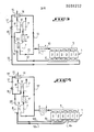
- FIG. 1 summarizing, by an overall functional block diagram, the various cases described below, symbolizing only the various circuits or flow paths of gaseous fluids concerned; solid lines in solid lines denote the permanent or preferably used gas streams while broken lines in dashed, dotted or mixed lines denote gas streams relating to various other embodiments of the invention.
- the reference C designates the supercharging air compressor which can be simple or with several, for example two, stages C, C ′ then comprising a low pressure compressor stage C discharging into a high pressure compressor stage C ′, possibly at through an intermediate air cooler not shown.
- burnt gases heat up in particular by direct contact various parts or parts of the engine such as the valves in particular of exhaust S which they bathe while flowing all around these when they leave the cylinders to be collected in the form of gas exhaust in at least one CE exhaust manifold through which they leave the engine M (delimited in the drawing by a rectangular frame in broken lines) to be brought to at least one gas turbine T intended, in certain special cases but not generally, to drive an air compressor C.
- a turbine can be constituted either by a single unit such as T or by several, for example two, stages, comprising a stage or a high pressure turbine T '(symbolized by a broken circle) and a low pressure stage or turbine T.
- the flow derived from compressed air A taken at the outlet of the compressor C or C 'but before the air cooler R, passes through a heat exchanger E where it is heated by the gases exiting GE from the turbine T and also passing through the heat exchanger E to then escape to the atmosphere.
- the flow derived from heated compressed air A ′ is then injected into the exhaust manifold GE to mix there with the exhaust gases supplying the turbine.
- the heat exchanger E can be replaced by an ejector traversed by a portion of the gases GE leaving the turbine T, which mix with the compressed air thereby giving a hot gas mixture A 'injected into the CE exhaust manifold.
- the flow derivative of compressed air A is taken after the air cooler R then passes, through A 1 , at least one hot exhaust valve S of the engine to be thus heated by simultaneously cooling this valve and this flow of heated air is injected into the CE exhaust manifold.
- the flow derived from compressed air, taken before the air cooler R, is heated by bathing, by A 2 , the hot exhaust manifold CE by flowing all around it. ci then this flow of heated air is injected into this exhaust manifold.
- the exemplary embodiment, shown in FIG. 2, shows an internal combustion engine such as a Diesel engine 1 with at least one row of cylinders in line 2, six in number for example.
- Engine could obviously include several rows of cylinders, for example two rows of cylinders arranged in a V, in which case there would advantageously be one supercharging group per row of cylinders.
- the or each row of cylinders of this engine comprises an air intake manifold 3 and at least one exhaust gas exhaust manifold 4 which, in the case of a row of four to ten cylinders, will advantageously be unique by row and of the so-called modular type with pulse converter composed of identical sections with cross section of constant or uniform free passage over the entire length of the collector.
- Such a type of collector has been described in particular in the main French patent No. 77.01937 and in its first and second certificates of addition No. 78.01782 and No. 79.22234.
- Such an exhaust manifold of the modular type with pulse converter is rigidly fixed and directly at the outlet of the exhaust gases from
- the engine produces a useful power collected on its shaft 5 intended to drive a receiving or use device 6 forming the load of the engine.
- the engine 1, constituting or forming part of the above-mentioned volumetric engine system, is supercharged by a turbocharger system with one or more stages, the air compressor system of which is directly mechanically driven by the turbine engine system.
- the air compressor system comprises an air compressor 7 and the turbine engine system comprises a turbine 8 directly mechanically coupled to the compressor 7 by an intermediate shaft 9.
- the outlet port of the compressor is connected by a return line ment 10 to the intake manifold 3 of the engine 1 through a terminal air cooler 11 for the cooling of the compressed air for boosting the engine and the passage of hot fluid to be cooled is mounted in series in this pipe . of repression.
- the gas inlet port of the turbine 8 is connected by a line 12 to the outlet port of the exhaust manifold 4 of the engine.
- the flow derived from compressed air is taken here before the cooling of compressed air by means of a compressed air bypass pipe 13 connected by its upstream end to the discharge pipe 10 before the compressed air refrigerant 11 and , by its downstream end, on the upstream end for example of the exhaust manifold 4, so that the flow derived from heated compressed air is injected into this manifold at the point of lowest instantaneous pressure of the exhaust gases in that -this.
- This place for recycling compressed air at the upstream end of the exhaust manifold is advantageous, since the first cylinder of the engine may possibly suck in fluid.
- a heat exchanger 14 is interposed in series on the one hand, by its passageway for cold or heated fluid, in the compressed air bypass duct 13 and on the other hand, by its passageway for heating fluid, in the pipe 15 for the gas outlet from the turbine 8. After the exit from the heat exchanger 14, this pipe 15 opens to the atmosphere, preferably after having passed through a silencer.
- the flow derived from compressed air is advantageously adjustable by selective variation, in particular so as to be able to be interrupted or stopped at the start of the volumetric motor system, when operating at a power level high enough for the efficiency of the turboshaft and compressor systems respectively to be good.
- the bypass duct 13 is provided with a valve or the like 16 which can be either of the all-or-nothing type, or with progressive closing and opening (to better increase the flow derived from compressed air with decreasing motor rotation speed 1).
- This valve must be closed beyond a certain power level, for example by having its control controlled by the instantaneous value of the air discharge pressure of the compressor or the air intake pressure to the engine (because the compressed air pressure at the outlet of the compressor is at least approximately proportional to the power of the engine in a relatively wide range of rotational speeds).
- a check valve or a non-return valve is advantageously mounted in the bypass duct 13, preferably before the valve 16.
- the valve 16 When the valve 16 is of the all-or-nothing type, it must be closed especially when starting engine 1 (i.e. when the intake air pressure is zero) and also when the gas pressure in the manifold exhaust 4 becomes greater than the compressed air pressure in the bypass duct 13, in particular in the absence of a check valve or of a non-return valve.
- the heat exchanger 14 can be either a fixed or static heat exchanger, of the type with bundles of coiled tubes or fins, of the plate type or of the heat pipe type, or a rotary regenerative heat exchanger driven in rotation for example by means of a PTO from a rotating shaft of the system.
- the invention is advantageously applicable to a power generator of the so-called compound type which generally consists of an internal combustion piston engine, at least one air compressor and at least one gas turbine with the existence of 'A mechanical coupling between at least two of these three units as well as a gas coupling at least between engine and turbine and between compressor and engine as well as possibly between compressor and turbine.
- the usable mechanical output power can thus be taken either on the motor shaft, or on the turbine shaft, or simultaneously on the two shafts (in which case, the useful powers collected respectively on the two shafts are mutually dependent reverse each other).
- the supercharging air compressor 7 is directly mechanically coupled by a link 18 (represented by a broken line in broken dashed lines in FIG.
- the internal combustion engine could possibly be an engine of the free piston type.
- the supercharging of the engine 1 is ensured by a two-stage turbocharger system comprising, on the one hand, a high pressure turbocharger composed of a high pressure compressor 7 directly mechanically driven by means of an intermediate coupling shaft 9 by a high pressure turbine 8 and, on the other hand, by a low pressure turbocharger composed of a low pressure compressor 7 'directly mechanically driven by the through a delivery tree intermediate placement 9 'by the low pressure turbine 8'.
- the first compression stage or low pressure compressor 7 ' discharges the compressed air through an intermediate air cooler 11' in the second compression stage or high pressure compressor 7 which then discharges the compressed air at high pressure to the engine intake manifold 3.
- the first turbine stage forming a high pressure turbine 8 receives the exhaust gases from the engine and then sends them to the second turbine stage forming the low pressure turbine 8 ′.
- the flow derived from compressed air is heated by heat exchange with at least part of the gases leaving the last turbine stage forming the low pressure turbine 8 '.
- the heating fluid passageway of the heat exchanger 14, interposed in the bypass duct 13 or 13 ′, is mounted in series in the gas outlet pipe 15 of the last stage of turbine forming turbine to low pressure 8 '.
- the variant embodiment according to FIG. 3 differs from the embodiment according to FIG. 2 only by the presence of a turbocharger group blowing in two stages with the aforementioned particular arrangement of the heat exchanger 14 relative to this group.
- the variant according to FIG. 4 differs from that according to FIG. 3 by the fact that the or each row, for example of six cylinders 2 of the engine 1 comprises two exhaust collectors of the pulse type 4a, 4b, respectively common to two different groups of three cylinders each, which collectors supply in parallel, by two separate inlets, the first turbine stage forming the high pressure turbine 8.
- the flow derived from heated air is not recycled to the exhaust manifolds due to the bursts of high pressure exhaust gas occurring in these exhaust manifolds but it will advantageously be injected between the two turbine stages in the gases leaving the first turbine stage forming the high pressure turbine 8, therefore before the entry of the second turbine stage forming the low pressure turbine 8 '.
- the bypass duct 13 ' after the outlet of the heat exchanger 14, is connected, by its downstream end, to the gas pipe 22 connecting the two successive turbine stages 8 and 8'.
- valve 16 with possibly its associated check valve 17 will advantageously be placed, in the bypass duct 13 or 13 ′, after the heat exchanger 14 to avoid fouling of the passageway compressed air in this exchanger by the engine exhaust gases when this valve is closed.
- the flow derived from compressed air is heated by heat taken from at least part of the exhaust gases, collected at the outlet, from the volumetric engine system.
- the heat exchange system comprises at least one heat exchanger interposed respectively by its passage for heating fluid in at least one exhaust gas flow path at the outlet of the volumetric engine system and by its compressed air passage in the bypass duct.
- the supply of energy at the only flow derived from compressed air takes place in the form of heat transferred to the latter by at least a portion of at least one exhaust manifold 4 forming a hot part of the engine 1, which hot part is thus simultaneously cooled by this circulation of compressed air.
- the heat exchanger 14 ' is then mounted around at least a portion of the exhaust manifold 4 which therefore forms an integral part of this exchanger by constituting the heating fluid passageway.
- the passageway for heated fluid (that is to say bypassed compressed air) of this heat exchanger 14 ′ is then constituted for example by an annular tubular enclosure surrounding the exhaust manifold 4.
- the circulation of the fluids respectively heated and heating in this heat exchanger 14 ′ will advantageously be done in a methodical manner, that is to say against the current, so that the bypass duct 13 will lead by its downstream end to the upstream end of the enclosure 14 ′ (that is to say on the side of the downstream end of the manifold 4) while this enclosure will communicate via its hot or downstream end preferably with the opposite end or upstream 23 of said collector.
- This embodiment according to FIG. 5 is in fact advantageous or advantageous only during the period of operation in transient mode of the internal combustion engine 1.
- the supply of energy at the single flow rate derived from compressed air takes place in the form of heat transferred to the latter by at least one hot member, for example mobile of the volumetric motor system, so that this hot member is thus simultaneously cooled by circulation of compressed air.
- the body hot mobile considered has a confined passageway for compressed air inserted in series in the bypass duct 13. It is then advantageous for the flow derived from compressed air to be taken after the compressed air for supercharging has cooled, it that is to say that the bypass duct 13 of compressed air is connected, by its upstream end, after the compressed air refrigerant 11.
- the heat is thus recovered on at least one hot valve in particular of exhaust 24 of the volumetric motor or motor system 1.
- This valve is crossed by at least one compressed air flow path cooler 25 mounted in series in the bypass duct 13, which advantageously joins, by its downstream end, the exhaust manifold 4.
- the supply of energy, at the flow rate derived from compressed air takes place in the form of heat and of mass live force by direct mixing of at least the major part of the flow rate.
- derived from compressed air with at least part of the flow of gas leaving the turbine engine system, in particular by suction suction effect and driving said gas by said compressed air acting in the form of at least one air jet.
- at least one ejector 27 is provided, the drive fluid flow path 27a of which is inserted in series in the compressed air bypass duct 13 and the entrained fluid suction pipe 27b of which is preferably connected by a bypass line 15 'to a gas outlet pipe 15 from the turbine 8.
- the mixture of gas and compressed air is brought through the pipe 13 preferably to the exhaust manifold 4 of motor 1 according to the configuration already described.
- the turbine is usually of the axial type and its gas inlet frame is generally connected to the exhaust gas inlet pipe by a diffuser, more particularly in the case of a manifold of modular type exhaust with pulse converter.
- a diffuser more particularly in the case of a manifold of modular type exhaust with pulse converter.
- At least part of the flow derived from compressed air is injected at an angle c (possibly selectively variable in the volute 28 of direct connection between at least one exhaust manifold 4 of the volumetric engine system 1 and at least one turbine 8 of the turbine engine system, substantially at the tangent connection point of the trajectory of entry of the exhaust gases into the volute with the start of their curved trajectory therein, so as to cause a deviation of said trajectory by fluidic effect in order to favorably influence the triangle of attack speeds of the stage or mobile blading of the turbine wheel, at an angle d, selectively adapted, possibly variable, depending on the current operating point of the turbine, thereby significantly improving the vi profile braids, which further increases the efficiency of hot air recycling.
- angle c possibly selectively variable in the volute 28 of direct connection between at least one exhaust manifold 4 of the volumetric engine system 1 and at least one turbine 8 of the turbine engine system, substantially at the tangent connection point of the trajectory of entry of the exhaust gases into the volute with the start of their curved trajectory therein,
- bypass duct 13 (or another bypass duct of compressed air in particular not previously heated) is connected, by its downstream end, optionally arbitrarily orientable or angularly adjustable, to the volute 28 of direct connection d 'at least one exhaust manifold 4 of the engine 1 with at least one turbine 8, substantially at the connection point of the straight inlet pipe 28a of the volute at the adjacent end of the curved passageway in this volute.
- This connection can be made by means of a tube or the like 29 for example pivotally articulated at 30 to the volute 28.
- the flow derived from compressed air, introduced into the volute 28, may not have received any prior energy report (in particular by reheating) i.e. can come directly from the compressor to the volute without having worked any heat recovery device (such as exchanger etc).
- this flow derived from unheated compressed air can be constituted by a second derived flow independent of the flow derived from compressed air provided with its energy supply (for example by reheating) described first in all previous embodiments according to Figures 1 to 7 and this variant can then be used in combination with the flow derived from heated compressed air, in which case there will be two flows derived from compressed air, one of which will be heated and the another will be unheated.
- This second unheated bypass flow can thus be brought to the volute 28 by another bypass duct separate or independent of the duct 13.
Landscapes
- Engineering & Computer Science (AREA)
- Chemical & Material Sciences (AREA)
- Combustion & Propulsion (AREA)
- Mechanical Engineering (AREA)
- General Engineering & Computer Science (AREA)
- Supercharger (AREA)
Applications Claiming Priority (2)
| Application Number | Priority Date | Filing Date | Title |
|---|---|---|---|
| FR8006439 | 1980-03-21 | ||
| FR8006439A FR2478736A1 (fr) | 1980-03-21 | 1980-03-21 | Procede et systeme de generation de puissance par moteur a combustion interne suralimente |
Publications (3)
| Publication Number | Publication Date |
|---|---|
| EP0038232A2 true EP0038232A2 (de) | 1981-10-21 |
| EP0038232A3 EP0038232A3 (en) | 1982-02-03 |
| EP0038232B1 EP0038232B1 (de) | 1986-02-19 |
Family
ID=9239981
Family Applications (1)
| Application Number | Title | Priority Date | Filing Date |
|---|---|---|---|
| EP81400450A Expired EP0038232B1 (de) | 1980-03-21 | 1981-03-20 | Verfahren und Anlage zur Leistungserzeugung durch eine Brennkraftmaschine |
Country Status (17)
| Country | Link |
|---|---|
| US (1) | US4404805A (de) |
| EP (1) | EP0038232B1 (de) |
| JP (1) | JPS56148617A (de) |
| KR (1) | KR840002482B1 (de) |
| AU (1) | AU6863481A (de) |
| BR (1) | BR8101578A (de) |
| CS (1) | CS247059B2 (de) |
| DD (1) | DD157571A5 (de) |
| DE (1) | DE3173791D1 (de) |
| DK (1) | DK154103B (de) |
| ES (1) | ES500592A0 (de) |
| FI (1) | FI66237C (de) |
| FR (1) | FR2478736A1 (de) |
| NO (1) | NO156764C (de) |
| PL (1) | PL136992B1 (de) |
| SU (1) | SU1111690A3 (de) |
| YU (1) | YU42561B (de) |
Cited By (8)
| Publication number | Priority date | Publication date | Assignee | Title |
|---|---|---|---|---|
| EP0091356A1 (de) * | 1982-04-02 | 1983-10-12 | Societe D'etudes De Machines Thermiques S.E.M.T. | Energierückgewinnungsmethode in einer Kraftanlage und Kraftanlage unter Zuhilfenahme dieser Methode |
| EP0117795B1 (de) * | 1983-02-03 | 1987-04-15 | Office National d'Etudes et de Recherches Aérospatiales (O.N.E.R.A.) | Turboaufgeladene Brennkraftmaschine |
| EP1348849A3 (de) * | 2002-03-26 | 2005-01-05 | General Motors Corporation | Regelbares Bypass-System eines Motor-Abgasturboladers und Verfahren dazu |
| CN102434270A (zh) * | 2011-11-25 | 2012-05-02 | 上海交通大学 | 压气机转速可变换的涡轮增压系统 |
| WO2014155013A1 (fr) * | 2013-03-29 | 2014-10-02 | Vianney Rabhi | Dispositif de suralimentation par turbocompresseur a soutirage d'air et regeneration |
| EP3078824A1 (de) * | 2015-03-30 | 2016-10-12 | AVL List GmbH | Brennkraftmaschine mit abgasenergienutzung und verfahren zum betrieb einer solchen brennkraftmaschine |
| WO2017194252A1 (fr) * | 2016-05-11 | 2017-11-16 | IFP Energies Nouvelles | Methode de controle de la quantite d'air introduit a l'admission d'un moteur a combustion interne suralimente par un turbocompresseur a simple entree |
| CN107923314A (zh) * | 2015-06-25 | 2018-04-17 | 普拉特 - 惠特尼加拿大公司 | 具有直接驱动的发电机的复合发动机组件 |
Families Citing this family (51)
| Publication number | Priority date | Publication date | Assignee | Title |
|---|---|---|---|---|
| FR2512496A1 (fr) * | 1981-09-10 | 1983-03-11 | Semt | Procede d'amenagement des conditions de fonctionnement d'un moteur a combustion interne et moteur ainsi amenage |
| JPS6055733U (ja) * | 1983-09-24 | 1985-04-18 | 三菱自動車工業株式会社 | 過給機付きエンジン |
| JPS6066829U (ja) * | 1983-10-15 | 1985-05-11 | いすゞ自動車株式会社 | 内燃機関の2段過給装置 |
| JPS6158935A (ja) * | 1984-08-30 | 1986-03-26 | Mazda Motor Corp | 過給機付きエンジンの2次空気供給装置 |
| JPS61247868A (ja) * | 1985-04-25 | 1986-11-05 | Mazda Motor Corp | エンジンの点火時期制御装置 |
| FR2585072A1 (fr) * | 1985-07-18 | 1987-01-23 | Melchior Cie | Perfectionnements aux moteurs a combustion interne suralimentes |
| FR2589518B1 (fr) * | 1985-11-06 | 1987-12-24 | Melchior Jean | Perfectionnements aux moteurs a combustion interne a deux temps et procede de mise en oeuvre |
| DE4319380C2 (de) * | 1992-06-12 | 1998-12-17 | Avl Verbrennungskraft Messtech | Brennkraftmaschine mit einem Abgasturbolader |
| JP3053703B2 (ja) * | 1992-08-25 | 2000-06-19 | 三菱電機株式会社 | 2次エア制御装置 |
| DE69813459T2 (de) * | 1997-11-18 | 2004-02-12 | Toyota Jidosha K.K., Toyota | Regelungsanlage eines Verbrennungsgeräts für eine Brennkraftmaschine |
| DE19837978B4 (de) * | 1998-04-16 | 2006-05-18 | Borgwarner Turbo Systems Gmbh | Turboaufgeladene Brennkraftmaschine |
| US6276139B1 (en) * | 2000-03-16 | 2001-08-21 | Ford Global Technologies, Inc. | Automotive engine with controlled exhaust temperature and oxygen concentration |
| FR2864994A1 (fr) * | 2004-01-12 | 2005-07-15 | Remi Curtil | Moteur a combustion interne suralimente par turbocompresseur |
| US20050221036A1 (en) * | 2004-04-01 | 2005-10-06 | The Coca-Cola Company | Polyester composition with enhanced gas barrier, articles made therewith, and methods |
| US20060168958A1 (en) * | 2005-01-02 | 2006-08-03 | Jan Vetrovec | Supercharged internal combustion engine |
| GB2438360B (en) * | 2005-03-09 | 2009-03-04 | Komatsu Mfg Co Ltd | Supercharged engine with egr device |
| US8545952B2 (en) * | 2005-06-07 | 2013-10-01 | The Coca-Cola Company | Polyester container with enhanced gas barrier and method |
| FR2891011A1 (fr) * | 2005-09-21 | 2007-03-23 | Melchior Jean F | Dispositif de suralimentation pour moteur a combustion interne, et vehicule automobile equipe d'un tel dispositif |
| US7820258B2 (en) * | 2005-10-05 | 2010-10-26 | The Coca-Cola Company | Container and composition for enhanced gas barrier properties |
| FR2895454B1 (fr) * | 2005-12-23 | 2011-10-14 | Renault Sas | Systeme a plusieurs etages de suralimentation |
| US8124202B2 (en) * | 2006-09-15 | 2012-02-28 | The Coca-Cola Company | Multilayer container for enhanced gas barrier properties |
| US7790077B2 (en) * | 2006-09-15 | 2010-09-07 | The Coca-Cola Company | Pressurized tooling for injection molding and method of using |
| US8266897B2 (en) | 2006-12-28 | 2012-09-18 | Caterpillar Inc. | Low temperature emission system having turbocharger bypass |
| JP2008202520A (ja) * | 2007-02-21 | 2008-09-04 | Toyota Industries Corp | 予混合圧縮着火機関及びその吸排気装置 |
| US7856825B2 (en) * | 2007-05-16 | 2010-12-28 | Pratt & Whitney Canada Corp. | Redundant mounting system for an internal fuel manifold |
| AT507096B1 (de) * | 2008-12-10 | 2010-02-15 | Man Nutzfahrzeuge Oesterreich | Antriebseinheit mit kühlkreislauf und separatem wärmerückgewinnungskreislauf |
| RU2395698C1 (ru) * | 2009-01-19 | 2010-07-27 | Александр Алексеевич Курбаков | Гидроэлектрическая силовая установка транспортного средства |
| KR101159886B1 (ko) * | 2009-01-30 | 2012-06-26 | 코오롱워터앤에너지 주식회사 | 트로멜 및 이것을 포함하는 폐기물 선별기 |
| AT512073B1 (de) * | 2011-10-20 | 2013-12-15 | Avl List Gmbh | Brennkraftmaschine |
| DE102012223808B4 (de) * | 2012-01-05 | 2019-06-13 | Ford Global Technologies, Llc | Brennkraftmaschine mit Abgasturboaufladung und Abgasrückführung und Verfahren zum Betreiben einer derartigen Brennkraftmaschine |
| WO2015052837A1 (ja) * | 2013-10-11 | 2015-04-16 | 三菱重工業株式会社 | 吸気バイパス装置を備えたエンジンシステム |
| FR3024178B1 (fr) * | 2014-07-24 | 2019-07-26 | IFP Energies Nouvelles | Dispositif de controle de la quantite d'air introduit a l'admission d'un moteur a combustion interne suralimente et procede utilisant un tel dispositif. |
| WO2016051324A1 (en) * | 2014-09-29 | 2016-04-07 | Boost Mechanics (Pty) Limited | A turbomachinery assembly for an internal combustion engine using a venturi apparatus |
| US9581060B2 (en) * | 2014-12-01 | 2017-02-28 | Dayco Ip Holdings, Llc | Evacuator system for supplying high suction vacuum or high suction flow rate |
| US9828953B2 (en) | 2014-12-01 | 2017-11-28 | Dayco Ip Holdings, Llc | Evacuator system having multi-port evacuator |
| FR3035151B1 (fr) | 2015-04-16 | 2017-04-21 | Ifp Energies Now | Dispositif integre a une culasse pour le controle d'une quantite d'air introduit a l'admission d'un moteur a combustion interne suralimente et procede utilisant un tel dispositif. |
| FR3035443B1 (fr) | 2015-04-21 | 2017-04-21 | Ifp Energies Now | Dispositif ameliore de controle de la quantite d'air introduit a l'admission d'un moteur a combustion interne suralimente et procede utilisant un tel dispositif |
| FR3035444B1 (fr) | 2015-04-22 | 2018-10-12 | IFP Energies Nouvelles | Methode de controle de la quantite d'air introduit a l'admission d'un moteur a combustion interne suralimente |
| FR3036738B1 (fr) | 2015-05-28 | 2017-05-26 | Ifp Energies Now | Dispositif pour le controle d'une quantite d'air introduit a l'admission d'un moteur a combustion interne suralimente et le refroidissement a l'echappement - procede utilisant un tel dispositif. |
| FR3037616B1 (fr) * | 2015-06-22 | 2018-11-16 | IFP Energies Nouvelles | Dispositif pour le controle d'une quantite d'air introduit a l'admission d'un moteur a combustion interne a au moins double etage de suralimentation et procede utilisant un tel dispositif. |
| US10710738B2 (en) | 2015-06-25 | 2020-07-14 | Pratt & Whitney Canada Corp. | Auxiliary power unit with intercooler |
| US10696417B2 (en) * | 2015-06-25 | 2020-06-30 | Pratt & Whitney Canada Corp. | Auxiliary power unit with excess air recovery |
| US10590842B2 (en) | 2015-06-25 | 2020-03-17 | Pratt & Whitney Canada Corp. | Compound engine assembly with bleed air |
| DE102015214404A1 (de) * | 2015-07-29 | 2017-02-02 | Robert Bosch Gmbh | Antriebsvorrichtung für ein Kraftfahrzeug, Verfahren zum Betreiben einer Antriebsvorrichtung |
| FR3053397B1 (fr) | 2016-06-30 | 2020-06-19 | IFP Energies Nouvelles | Dispositif et methode de controle de l'introduction d'air et de gaz d'echappement a l'admission d'un moteur a combustion interne suralimente |
| FR3054602A1 (fr) | 2016-07-29 | 2018-02-02 | IFP Energies Nouvelles | Dispositif et methode de controle de l'introduction conjointe d'air et de gaz d'echappement a l'admission d'un moteur a combustion interne suralimente. |
| FR3060655B1 (fr) | 2016-12-15 | 2018-12-07 | IFP Energies Nouvelles | Methode de controle de la quantite d'air comprime introduit a l'admission d'un moteur a combustion interne suralimente |
| FR3063111B1 (fr) * | 2017-02-23 | 2021-07-30 | Ifp Energies Now | Dispositif de controle de l'introduction de la quantite de fluide a l'admission d'un moteur a combustion interne suralimente equipe d'un circuit de recirculation de gaz d'echappement et methode utilisant un tel dispositif |
| FR3074533B1 (fr) * | 2017-12-06 | 2020-11-06 | Safran Aircraft Engines | Circuit de commande hydraulique et pneumatique pour turboreacteur a echangeur de chaleur carburant/air |
| DE102018209698A1 (de) | 2018-06-15 | 2019-12-19 | Robert Bosch Gmbh | Verfahren und Steuergerät zum Betreiben einer Antriebsvorrichtung, Antriebsvorrichtung |
| GB2594058B (en) * | 2020-04-09 | 2023-10-25 | Bowman Power Group Ltd | Turbocharged engine systems and a method of increasing boost pressure |
Family Cites Families (22)
| Publication number | Priority date | Publication date | Assignee | Title |
|---|---|---|---|---|
| US2172809A (en) * | 1935-08-20 | 1939-09-12 | Maschf Augsburg Nuernberg Ag | Method of controlling the supercharging pressure in internal combustion engines |
| US2633698A (en) * | 1948-02-05 | 1953-04-07 | Nettel Frederick | Turbosupercharger means to heat intake of compression-ignition engine for starting |
| DE801596C (de) * | 1948-10-02 | 1951-01-15 | Maschf Augsburg Nuernberg Ag | Aufgeladene Brennkraftmaschine fuer Fahrzeugantrieb |
| US2898731A (en) * | 1953-09-11 | 1959-08-11 | Power Jets Res & Dev Ltd | Power producing equipment incorporating gas turbine plant |
| DE1051069B (de) * | 1956-05-07 | 1959-02-19 | Georg Sonnefeld Dr Ing | Gasturbinenanlage fuer Flugzeugtriebwerke mit Propellerturbinen und Turbostrahlduesen |
| US3102381A (en) * | 1960-08-11 | 1963-09-03 | British Internal Combust Eng | Engine inlet-exhaust bypass means for exhaust driven superchargers |
| US3103780A (en) * | 1960-08-11 | 1963-09-17 | British Internal Combust Eng | Turbocharged internal combustion engines |
| FR1406599A (fr) | 1964-06-09 | 1965-07-23 | Hispano Suiza Sa | Perfectionnements apportés aux moteurs diesel suralimentés |
| FR1406600A (fr) * | 1964-06-09 | 1965-07-23 | Hispano Suiza Sa | Perfectionnements apportés aux moteurs diesel à suralimentation réfrigérée par turbo-refroidissement |
| US3300964A (en) * | 1965-06-14 | 1967-01-31 | Edward R Knopp | Anti-smog device |
| US3513929A (en) * | 1967-08-25 | 1970-05-26 | Exxon Research Engineering Co | Low-polluting engine and drive system |
| SE352136B (de) * | 1971-04-05 | 1972-12-18 | Saab Scania Ab | |
| IT980866B (it) * | 1973-04-18 | 1974-10-10 | Fiat Spa | Dispositivo di sovralimentazione per motori endotermici alternativi |
| SU457813A1 (ru) * | 1974-02-01 | 1975-01-25 | Московское Ордена Ленина И Ордена Трудового Красного Знамени Высшее Техническое Училище Им.Н.Э.Баумана | Комбинированна энергетическа установка |
| DE2438162A1 (de) * | 1974-08-08 | 1976-02-26 | Motoren Turbinen Union | Verfahren zum betrieb einer brennkraftmaschine mit abgasturbolader und einer brennkammer und vorrichtungen zur durchfuehrung des verfahrens |
| US3996738A (en) * | 1975-04-11 | 1976-12-14 | Siegfried Justus | Gas turbine circuit system |
| DE2706696C2 (de) * | 1977-02-17 | 1982-04-29 | Mtu Motoren- Und Turbinen-Union Friedrichshafen Gmbh, 7990 Friedrichshafen | Verfahren zum Anlassen der Brennkammer einer Brennkraftmaschine |
| JPS5419008A (en) * | 1977-07-13 | 1979-02-13 | Nissan Motor Co Ltd | Turbocharger equipment |
| DE2757236C3 (de) * | 1977-12-22 | 1982-02-25 | Dr.Ing.H.C. F. Porsche Ag, 7000 Stuttgart | Antriebsaggregat, insbesondere für Kraftfahrzeuge |
| DE2829150A1 (de) | 1978-07-03 | 1980-01-24 | Barmag Barmer Maschf | Abgasturbolader |
| CH639172A5 (de) * | 1979-01-31 | 1983-10-31 | Bbc Brown Boveri & Cie | Verbrennungsmotor mit turbolader mit einem automatischen bypass. |
| US4367626A (en) * | 1979-07-16 | 1983-01-11 | Schwartzman Everett H | Turbocharger systems |
-
1980
- 1980-03-21 FR FR8006439A patent/FR2478736A1/fr active Granted
-
1981
- 1981-03-16 FI FI810800A patent/FI66237C/fi not_active IP Right Cessation
- 1981-03-17 US US06/244,624 patent/US4404805A/en not_active Expired - Fee Related
- 1981-03-18 DK DK123181AA patent/DK154103B/da not_active Application Discontinuation
- 1981-03-18 BR BR8101578A patent/BR8101578A/pt unknown
- 1981-03-20 SU SU813259054A patent/SU1111690A3/ru active
- 1981-03-20 YU YU740/81A patent/YU42561B/xx unknown
- 1981-03-20 PL PL1981230231A patent/PL136992B1/pl unknown
- 1981-03-20 CS CS812055A patent/CS247059B2/cs unknown
- 1981-03-20 NO NO810955A patent/NO156764C/no unknown
- 1981-03-20 DE DE8181400450T patent/DE3173791D1/de not_active Expired
- 1981-03-20 DD DD81228496A patent/DD157571A5/de unknown
- 1981-03-20 EP EP81400450A patent/EP0038232B1/de not_active Expired
- 1981-03-21 ES ES500592A patent/ES500592A0/es active Granted
- 1981-03-21 KR KR1019810000939A patent/KR840002482B1/ko not_active Expired
- 1981-03-23 AU AU68634/81A patent/AU6863481A/en not_active Abandoned
- 1981-03-23 JP JP4224781A patent/JPS56148617A/ja active Pending
Cited By (15)
| Publication number | Priority date | Publication date | Assignee | Title |
|---|---|---|---|---|
| EP0091356A1 (de) * | 1982-04-02 | 1983-10-12 | Societe D'etudes De Machines Thermiques S.E.M.T. | Energierückgewinnungsmethode in einer Kraftanlage und Kraftanlage unter Zuhilfenahme dieser Methode |
| US4513572A (en) * | 1982-04-02 | 1985-04-30 | Societe D'etudes De Machines Thermiques, S.E.M.T. | Method of recovering energy in a power generator and power generator for carrying out the said method |
| EP0117795B1 (de) * | 1983-02-03 | 1987-04-15 | Office National d'Etudes et de Recherches Aérospatiales (O.N.E.R.A.) | Turboaufgeladene Brennkraftmaschine |
| EP1348849A3 (de) * | 2002-03-26 | 2005-01-05 | General Motors Corporation | Regelbares Bypass-System eines Motor-Abgasturboladers und Verfahren dazu |
| US6912852B2 (en) | 2002-03-26 | 2005-07-05 | Electro-Motive Diesel, Inc. | Method for engine condition control with turbocompressor controllable bypass |
| CN102434270A (zh) * | 2011-11-25 | 2012-05-02 | 上海交通大学 | 压气机转速可变换的涡轮增压系统 |
| WO2014155013A1 (fr) * | 2013-03-29 | 2014-10-02 | Vianney Rabhi | Dispositif de suralimentation par turbocompresseur a soutirage d'air et regeneration |
| FR3003900A1 (fr) * | 2013-03-29 | 2014-10-03 | Vianney Rabhi | Dispositif de suralimentation par turbocompresseur a soutirage d'air et regeneration |
| FR3003901A1 (fr) * | 2013-03-29 | 2014-10-03 | Vianney Rabhi | Dispositif de suralimentation par turbocompresseur a soutirage d'air et regeneration |
| EP3078824A1 (de) * | 2015-03-30 | 2016-10-12 | AVL List GmbH | Brennkraftmaschine mit abgasenergienutzung und verfahren zum betrieb einer solchen brennkraftmaschine |
| CN107923314A (zh) * | 2015-06-25 | 2018-04-17 | 普拉特 - 惠特尼加拿大公司 | 具有直接驱动的发电机的复合发动机组件 |
| WO2017194252A1 (fr) * | 2016-05-11 | 2017-11-16 | IFP Energies Nouvelles | Methode de controle de la quantite d'air introduit a l'admission d'un moteur a combustion interne suralimente par un turbocompresseur a simple entree |
| FR3051225A1 (fr) * | 2016-05-11 | 2017-11-17 | Ifp Energies Now | Methode de controle de la quantite d'air introduit a l'admission d'un moteur a combustion interne suralimente par un turbocompresseur a simple entree |
| US20190128174A1 (en) * | 2016-05-11 | 2019-05-02 | IFP Energies Nouvelles | Method for controlling the quantity of air introduced to the intake of a supercharged internal combustion engine by a single-inlet turbocompressor |
| US10724427B2 (en) | 2016-05-11 | 2020-07-28 | IFP Energies Nouvelles | Method for controlling the quantity of air introduced to the intake of a supercharged internal combustion engine by a single-inlet turbocompressor |
Also Published As
| Publication number | Publication date |
|---|---|
| NO156764B (no) | 1987-08-10 |
| DK123181A (da) | 1981-09-22 |
| DE3173791D1 (en) | 1986-03-27 |
| YU74081A (en) | 1985-08-31 |
| KR840002482B1 (ko) | 1984-12-31 |
| NO156764C (no) | 1987-11-18 |
| EP0038232A3 (en) | 1982-02-03 |
| FR2478736B1 (de) | 1983-07-22 |
| FI66237C (fi) | 1984-09-10 |
| ES8202097A1 (es) | 1982-01-01 |
| DD157571A5 (de) | 1982-11-17 |
| BR8101578A (pt) | 1981-09-22 |
| US4404805A (en) | 1983-09-20 |
| SU1111690A3 (ru) | 1984-08-30 |
| PL230231A1 (de) | 1981-10-30 |
| FI810800L (fi) | 1981-09-22 |
| AU6863481A (en) | 1981-09-24 |
| JPS56148617A (en) | 1981-11-18 |
| ES500592A0 (es) | 1982-01-01 |
| DK154103B (da) | 1988-10-10 |
| YU42561B (en) | 1988-10-31 |
| FI66237B (fi) | 1984-05-31 |
| CS247059B2 (en) | 1986-11-13 |
| KR830005461A (ko) | 1983-08-13 |
| FR2478736A1 (fr) | 1981-09-25 |
| NO810955L (no) | 1981-09-22 |
| EP0038232B1 (de) | 1986-02-19 |
| PL136992B1 (en) | 1986-04-30 |
Similar Documents
| Publication | Publication Date | Title |
|---|---|---|
| EP0038232A2 (de) | Verfahren und Anlage zur Leistungserzeugung durch eine Brennkraftmaschine | |
| US5894719A (en) | Method and apparatus for cold gas reinjection in through-flow and reverse-flow wave rotors | |
| FR2611229A1 (fr) | Turboreacteur a soufflante carenee a cycle compound | |
| EP1483489B1 (de) | Gasturbine mit intermittierender verbrennung | |
| EP0091356B1 (de) | Energierückgewinnungsmethode in einer Kraftanlage und Kraftanlage unter Zuhilfenahme dieser Methode | |
| EP1503061A1 (de) | Verfahren zur Kühlung von heissen Turbinenbauteilen mittels eines teilweise in einem externen Wärmetauscher gekühlten Luftstromes und so gekühltes Turbinentriebwerk | |
| FR2557207A1 (fr) | Systeme de refroidissement pour fournir un tampon d'air a un compartiment de palier | |
| FR2598179A1 (fr) | Dispositif de transfert d'air de refroidissement pour une turbine | |
| FR2920470A1 (fr) | Dispositif pour faciliter le refroidissemnt d'un composant de turbine a vapeur. | |
| FR2875269A1 (fr) | Systeme de refroidissement pour moteur a turbine a gaz ayant un systeme central ameliore | |
| EP2414652B1 (de) | Aufgeladener verbrennungsmotor | |
| EP3303798A1 (de) | Aufgeladener motor mit zwei abgasrohren und regelventil | |
| FR2516169A1 (fr) | Injecteur de carburant pour moteurs a turbines a gaz | |
| FR2482196A1 (fr) | Echangeur de chaleur pour moteur a reaction a double flux | |
| CA3104864A1 (fr) | Procede et dispositif de conversion d'energie thermique | |
| WO2009118471A1 (fr) | Moteur a combustion interne a suralimentation pulsee | |
| WO2006082302A1 (fr) | Moteur alternatif a combustion interne et procede d'elimination des particules des gaz brules pour un tel moteur alternatif | |
| EP1359309B1 (de) | Gasturbine mit einer Loben- und Röhren-Mischvorrichtung | |
| WO2022189712A1 (fr) | Dispositif de turbomachine tritherme et vehicule comprenant un tel dispositif | |
| FR3070725B1 (fr) | Turbopompe cinetique avec un dispositif de variation de vitesse pour un circuit ferme, en particulier de type a cycle de rankine, notamment pour un vehicule automobile | |
| FR2531744A1 (fr) | Turbine a pales croisees | |
| FR2491997A1 (fr) | Installation a turbine a vapeur et a gaz | |
| CH97143A (fr) | Procédé pour la production de force motrice au moyen d'une turbine à combustion. | |
| FR3133404A1 (fr) | Système de suralimentation en air pour système de conditionnement de carburant et procédé d’utilisation | |
| RU2315191C1 (ru) | Газотурбинный двигатель |
Legal Events
| Date | Code | Title | Description |
|---|---|---|---|
| PUAI | Public reference made under article 153(3) epc to a published international application that has entered the european phase |
Free format text: ORIGINAL CODE: 0009012 |
|
| AK | Designated contracting states |
Designated state(s): BE CH DE GB IT NL SE |
|
| PUAL | Search report despatched |
Free format text: ORIGINAL CODE: 0009013 |
|
| AK | Designated contracting states |
Designated state(s): BE CH DE GB IT NL SE |
|
| 17P | Request for examination filed |
Effective date: 19820623 |
|
| GRAA | (expected) grant |
Free format text: ORIGINAL CODE: 0009210 |
|
| AK | Designated contracting states |
Designated state(s): BE CH DE GB IT LI NL SE |
|
| ITF | It: translation for a ep patent filed | ||
| REF | Corresponds to: |
Ref document number: 3173791 Country of ref document: DE Date of ref document: 19860327 |
|
| PLBE | No opposition filed within time limit |
Free format text: ORIGINAL CODE: 0009261 |
|
| STAA | Information on the status of an ep patent application or granted ep patent |
Free format text: STATUS: NO OPPOSITION FILED WITHIN TIME LIMIT |
|
| 26N | No opposition filed | ||
| PGFP | Annual fee paid to national office [announced via postgrant information from national office to epo] |
Ref country code: NL Payment date: 19870331 Year of fee payment: 7 |
|
| PG25 | Lapsed in a contracting state [announced via postgrant information from national office to epo] |
Ref country code: GB Effective date: 19890320 |
|
| PG25 | Lapsed in a contracting state [announced via postgrant information from national office to epo] |
Ref country code: SE Effective date: 19890321 |
|
| PG25 | Lapsed in a contracting state [announced via postgrant information from national office to epo] |
Ref country code: LI Effective date: 19890331 Ref country code: CH Effective date: 19890331 Ref country code: BE Effective date: 19890331 |
|
| BERE | Be: lapsed |
Owner name: SOC. D'ETUDES DE MACHINES THERMIQUES SEMT Effective date: 19890331 |
|
| PG25 | Lapsed in a contracting state [announced via postgrant information from national office to epo] |
Ref country code: NL Effective date: 19891001 |
|
| GBPC | Gb: european patent ceased through non-payment of renewal fee | ||
| NLV4 | Nl: lapsed or anulled due to non-payment of the annual fee | ||
| REG | Reference to a national code |
Ref country code: CH Ref legal event code: PL |
|
| PG25 | Lapsed in a contracting state [announced via postgrant information from national office to epo] |
Ref country code: DE Effective date: 19891201 |
|
| EUG | Se: european patent has lapsed |
Ref document number: 81400450.3 Effective date: 19900124 |