EP3020939B1 - Motorsystem mit einlass-bypassvorrichtung - Google Patents
Motorsystem mit einlass-bypassvorrichtung Download PDFInfo
- Publication number
- EP3020939B1 EP3020939B1 EP13895188.4A EP13895188A EP3020939B1 EP 3020939 B1 EP3020939 B1 EP 3020939B1 EP 13895188 A EP13895188 A EP 13895188A EP 3020939 B1 EP3020939 B1 EP 3020939B1
- Authority
- EP
- European Patent Office
- Prior art keywords
- bypass
- channel
- turbine
- exhaust
- intake
- Prior art date
- Legal status (The legal status is an assumption and is not a legal conclusion. Google has not performed a legal analysis and makes no representation as to the accuracy of the status listed.)
- Active
Links
Images


Classifications
-
- F—MECHANICAL ENGINEERING; LIGHTING; HEATING; WEAPONS; BLASTING
- F02—COMBUSTION ENGINES; HOT-GAS OR COMBUSTION-PRODUCT ENGINE PLANTS
- F02D—CONTROLLING COMBUSTION ENGINES
- F02D41/00—Electrical control of supply of combustible mixture or its constituents
- F02D41/0002—Controlling intake air
- F02D41/0007—Controlling intake air for control of turbo-charged or super-charged engines
-
- F—MECHANICAL ENGINEERING; LIGHTING; HEATING; WEAPONS; BLASTING
- F01—MACHINES OR ENGINES IN GENERAL; ENGINE PLANTS IN GENERAL; STEAM ENGINES
- F01D—NON-POSITIVE DISPLACEMENT MACHINES OR ENGINES, e.g. STEAM TURBINES
- F01D17/00—Regulating or controlling by varying flow
- F01D17/10—Final actuators
- F01D17/105—Final actuators by passing part of the fluid
-
- F—MECHANICAL ENGINEERING; LIGHTING; HEATING; WEAPONS; BLASTING
- F01—MACHINES OR ENGINES IN GENERAL; ENGINE PLANTS IN GENERAL; STEAM ENGINES
- F01D—NON-POSITIVE DISPLACEMENT MACHINES OR ENGINES, e.g. STEAM TURBINES
- F01D17/00—Regulating or controlling by varying flow
- F01D17/10—Final actuators
- F01D17/12—Final actuators arranged in stator parts
- F01D17/14—Final actuators arranged in stator parts varying effective cross-sectional area of nozzles or guide conduits
- F01D17/146—Final actuators arranged in stator parts varying effective cross-sectional area of nozzles or guide conduits by throttling the volute inlet of radial machines or engines
-
- F—MECHANICAL ENGINEERING; LIGHTING; HEATING; WEAPONS; BLASTING
- F01—MACHINES OR ENGINES IN GENERAL; ENGINE PLANTS IN GENERAL; STEAM ENGINES
- F01D—NON-POSITIVE DISPLACEMENT MACHINES OR ENGINES, e.g. STEAM TURBINES
- F01D25/00—Component parts, details, or accessories, not provided for in, or of interest apart from, other groups
- F01D25/08—Cooling; Heating; Heat-insulation
- F01D25/10—Heating, e.g. warming-up before starting
-
- F—MECHANICAL ENGINEERING; LIGHTING; HEATING; WEAPONS; BLASTING
- F01—MACHINES OR ENGINES IN GENERAL; ENGINE PLANTS IN GENERAL; STEAM ENGINES
- F01N—GAS-FLOW SILENCERS OR EXHAUST APPARATUS FOR MACHINES OR ENGINES IN GENERAL; GAS-FLOW SILENCERS OR EXHAUST APPARATUS FOR INTERNAL-COMBUSTION ENGINES
- F01N3/00—Exhaust or silencing apparatus having means for purifying, rendering innocuous, or otherwise treating exhaust
- F01N3/02—Exhaust or silencing apparatus having means for purifying, rendering innocuous, or otherwise treating exhaust for cooling, or for removing solid constituents of, exhaust
- F01N3/0205—Exhaust or silencing apparatus having means for purifying, rendering innocuous, or otherwise treating exhaust for cooling, or for removing solid constituents of, exhaust using heat exchangers
-
- F—MECHANICAL ENGINEERING; LIGHTING; HEATING; WEAPONS; BLASTING
- F01—MACHINES OR ENGINES IN GENERAL; ENGINE PLANTS IN GENERAL; STEAM ENGINES
- F01N—GAS-FLOW SILENCERS OR EXHAUST APPARATUS FOR MACHINES OR ENGINES IN GENERAL; GAS-FLOW SILENCERS OR EXHAUST APPARATUS FOR INTERNAL-COMBUSTION ENGINES
- F01N3/00—Exhaust or silencing apparatus having means for purifying, rendering innocuous, or otherwise treating exhaust
- F01N3/02—Exhaust or silencing apparatus having means for purifying, rendering innocuous, or otherwise treating exhaust for cooling, or for removing solid constituents of, exhaust
- F01N3/05—Exhaust or silencing apparatus having means for purifying, rendering innocuous, or otherwise treating exhaust for cooling, or for removing solid constituents of, exhaust by means of air, e.g. by mixing exhaust with air
- F01N3/055—Exhaust or silencing apparatus having means for purifying, rendering innocuous, or otherwise treating exhaust for cooling, or for removing solid constituents of, exhaust by means of air, e.g. by mixing exhaust with air without contact between air and exhaust gases
-
- F—MECHANICAL ENGINEERING; LIGHTING; HEATING; WEAPONS; BLASTING
- F01—MACHINES OR ENGINES IN GENERAL; ENGINE PLANTS IN GENERAL; STEAM ENGINES
- F01N—GAS-FLOW SILENCERS OR EXHAUST APPARATUS FOR MACHINES OR ENGINES IN GENERAL; GAS-FLOW SILENCERS OR EXHAUST APPARATUS FOR INTERNAL-COMBUSTION ENGINES
- F01N3/00—Exhaust or silencing apparatus having means for purifying, rendering innocuous, or otherwise treating exhaust
- F01N3/08—Exhaust or silencing apparatus having means for purifying, rendering innocuous, or otherwise treating exhaust for rendering innocuous
- F01N3/10—Exhaust or silencing apparatus having means for purifying, rendering innocuous, or otherwise treating exhaust for rendering innocuous by thermal or catalytic conversion of noxious components of exhaust
- F01N3/24—Exhaust or silencing apparatus having means for purifying, rendering innocuous, or otherwise treating exhaust for rendering innocuous by thermal or catalytic conversion of noxious components of exhaust characterised by constructional aspects of converting apparatus
- F01N3/28—Construction of catalytic reactors
- F01N3/2882—Catalytic reactors combined or associated with other devices, e.g. exhaust silencers or other exhaust purification devices
- F01N3/2889—Catalytic reactors combined or associated with other devices, e.g. exhaust silencers or other exhaust purification devices with heat exchangers in a single housing
-
- F—MECHANICAL ENGINEERING; LIGHTING; HEATING; WEAPONS; BLASTING
- F01—MACHINES OR ENGINES IN GENERAL; ENGINE PLANTS IN GENERAL; STEAM ENGINES
- F01N—GAS-FLOW SILENCERS OR EXHAUST APPARATUS FOR MACHINES OR ENGINES IN GENERAL; GAS-FLOW SILENCERS OR EXHAUST APPARATUS FOR INTERNAL-COMBUSTION ENGINES
- F01N5/00—Exhaust or silencing apparatus combined or associated with devices profiting by exhaust energy
- F01N5/02—Exhaust or silencing apparatus combined or associated with devices profiting by exhaust energy the devices using heat
-
- F—MECHANICAL ENGINEERING; LIGHTING; HEATING; WEAPONS; BLASTING
- F02—COMBUSTION ENGINES; HOT-GAS OR COMBUSTION-PRODUCT ENGINE PLANTS
- F02B—INTERNAL-COMBUSTION PISTON ENGINES; COMBUSTION ENGINES IN GENERAL
- F02B33/00—Engines characterised by provision of pumps for charging or scavenging
- F02B33/32—Engines with pumps other than of reciprocating-piston type
- F02B33/34—Engines with pumps other than of reciprocating-piston type with rotary pumps
- F02B33/40—Engines with pumps other than of reciprocating-piston type with rotary pumps of non-positive-displacement type
-
- F—MECHANICAL ENGINEERING; LIGHTING; HEATING; WEAPONS; BLASTING
- F02—COMBUSTION ENGINES; HOT-GAS OR COMBUSTION-PRODUCT ENGINE PLANTS
- F02B—INTERNAL-COMBUSTION PISTON ENGINES; COMBUSTION ENGINES IN GENERAL
- F02B37/00—Engines characterised by provision of pumps driven at least for part of the time by exhaust
- F02B37/12—Control of the pumps
- F02B37/16—Control of the pumps by bypassing charging air
- F02B37/162—Control of the pumps by bypassing charging air by bypassing, e.g. partially, intake air from pump inlet to pump outlet
-
- F—MECHANICAL ENGINEERING; LIGHTING; HEATING; WEAPONS; BLASTING
- F02—COMBUSTION ENGINES; HOT-GAS OR COMBUSTION-PRODUCT ENGINE PLANTS
- F02B—INTERNAL-COMBUSTION PISTON ENGINES; COMBUSTION ENGINES IN GENERAL
- F02B37/00—Engines characterised by provision of pumps driven at least for part of the time by exhaust
- F02B37/12—Control of the pumps
- F02B37/16—Control of the pumps by bypassing charging air
- F02B37/168—Control of the pumps by bypassing charging air into the exhaust conduit
-
- F—MECHANICAL ENGINEERING; LIGHTING; HEATING; WEAPONS; BLASTING
- F02—COMBUSTION ENGINES; HOT-GAS OR COMBUSTION-PRODUCT ENGINE PLANTS
- F02B—INTERNAL-COMBUSTION PISTON ENGINES; COMBUSTION ENGINES IN GENERAL
- F02B37/00—Engines characterised by provision of pumps driven at least for part of the time by exhaust
- F02B37/12—Control of the pumps
- F02B37/20—Control of the pumps by increasing exhaust energy, e.g. using combustion chamber by after-burning
-
- F—MECHANICAL ENGINEERING; LIGHTING; HEATING; WEAPONS; BLASTING
- F02—COMBUSTION ENGINES; HOT-GAS OR COMBUSTION-PRODUCT ENGINE PLANTS
- F02B—INTERNAL-COMBUSTION PISTON ENGINES; COMBUSTION ENGINES IN GENERAL
- F02B39/00—Component parts, details, or accessories relating to, driven charging or scavenging pumps, not provided for in groups F02B33/00 - F02B37/00
- F02B39/005—Cooling of pump drives
-
- F—MECHANICAL ENGINEERING; LIGHTING; HEATING; WEAPONS; BLASTING
- F02—COMBUSTION ENGINES; HOT-GAS OR COMBUSTION-PRODUCT ENGINE PLANTS
- F02C—GAS-TURBINE PLANTS; AIR INTAKES FOR JET-PROPULSION PLANTS; CONTROLLING FUEL SUPPLY IN AIR-BREATHING JET-PROPULSION PLANTS
- F02C3/00—Gas-turbine plants characterised by the use of combustion products as the working fluid
- F02C3/04—Gas-turbine plants characterised by the use of combustion products as the working fluid having a turbine driving a compressor
- F02C3/13—Gas-turbine plants characterised by the use of combustion products as the working fluid having a turbine driving a compressor having variable working fluid interconnections between turbines or compressors or stages of different rotors
-
- F—MECHANICAL ENGINEERING; LIGHTING; HEATING; WEAPONS; BLASTING
- F02—COMBUSTION ENGINES; HOT-GAS OR COMBUSTION-PRODUCT ENGINE PLANTS
- F02C—GAS-TURBINE PLANTS; AIR INTAKES FOR JET-PROPULSION PLANTS; CONTROLLING FUEL SUPPLY IN AIR-BREATHING JET-PROPULSION PLANTS
- F02C6/00—Plural gas-turbine plants; Combinations of gas-turbine plants with other apparatus; Adaptations of gas-turbine plants for special use
- F02C6/04—Gas-turbine plants providing heated or pressurised working fluid for other apparatus, e.g. without mechanical power output
- F02C6/10—Gas-turbine plants providing heated or pressurised working fluid for other apparatus, e.g. without mechanical power output supplying working fluid to a user, e.g. a chemical process, which returns working fluid to a turbine of the plant
- F02C6/12—Turbochargers, i.e. plants for augmenting mechanical power output of internal-combustion piston engines by increase of charge pressure
-
- F—MECHANICAL ENGINEERING; LIGHTING; HEATING; WEAPONS; BLASTING
- F02—COMBUSTION ENGINES; HOT-GAS OR COMBUSTION-PRODUCT ENGINE PLANTS
- F02C—GAS-TURBINE PLANTS; AIR INTAKES FOR JET-PROPULSION PLANTS; CONTROLLING FUEL SUPPLY IN AIR-BREATHING JET-PROPULSION PLANTS
- F02C9/00—Controlling gas-turbine plants; Controlling fuel supply in air- breathing jet-propulsion plants
- F02C9/16—Control of working fluid flow
- F02C9/18—Control of working fluid flow by bleeding, bypassing or acting on variable working fluid interconnections between turbines or compressors or their stages
-
- F—MECHANICAL ENGINEERING; LIGHTING; HEATING; WEAPONS; BLASTING
- F02—COMBUSTION ENGINES; HOT-GAS OR COMBUSTION-PRODUCT ENGINE PLANTS
- F02D—CONTROLLING COMBUSTION ENGINES
- F02D41/00—Electrical control of supply of combustible mixture or its constituents
- F02D41/24—Electrical control of supply of combustible mixture or its constituents characterised by the use of digital means
- F02D41/26—Electrical control of supply of combustible mixture or its constituents characterised by the use of digital means using computer, e.g. microprocessor
-
- F—MECHANICAL ENGINEERING; LIGHTING; HEATING; WEAPONS; BLASTING
- F04—POSITIVE - DISPLACEMENT MACHINES FOR LIQUIDS; PUMPS FOR LIQUIDS OR ELASTIC FLUIDS
- F04D—NON-POSITIVE-DISPLACEMENT PUMPS
- F04D27/00—Control, e.g. regulation, of pumps, pumping installations or pumping systems specially adapted for elastic fluids
- F04D27/02—Surge control
- F04D27/0207—Surge control by bleeding, bypassing or recycling fluids
- F04D27/0223—Control schemes therefor
-
- F—MECHANICAL ENGINEERING; LIGHTING; HEATING; WEAPONS; BLASTING
- F02—COMBUSTION ENGINES; HOT-GAS OR COMBUSTION-PRODUCT ENGINE PLANTS
- F02B—INTERNAL-COMBUSTION PISTON ENGINES; COMBUSTION ENGINES IN GENERAL
- F02B37/00—Engines characterised by provision of pumps driven at least for part of the time by exhaust
- F02B37/12—Control of the pumps
- F02B2037/125—Control for avoiding pump stall or surge
-
- F—MECHANICAL ENGINEERING; LIGHTING; HEATING; WEAPONS; BLASTING
- F05—INDEXING SCHEMES RELATING TO ENGINES OR PUMPS IN VARIOUS SUBCLASSES OF CLASSES F01-F04
- F05D—INDEXING SCHEME FOR ASPECTS RELATING TO NON-POSITIVE-DISPLACEMENT MACHINES OR ENGINES, GAS-TURBINES OR JET-PROPULSION PLANTS
- F05D2270/00—Control
- F05D2270/01—Purpose of the control system
- F05D2270/10—Purpose of the control system to cope with, or avoid, compressor flow instabilities
- F05D2270/101—Compressor surge or stall
-
- F—MECHANICAL ENGINEERING; LIGHTING; HEATING; WEAPONS; BLASTING
- F05—INDEXING SCHEMES RELATING TO ENGINES OR PUMPS IN VARIOUS SUBCLASSES OF CLASSES F01-F04
- F05D—INDEXING SCHEME FOR ASPECTS RELATING TO NON-POSITIVE-DISPLACEMENT MACHINES OR ENGINES, GAS-TURBINES OR JET-PROPULSION PLANTS
- F05D2270/00—Control
- F05D2270/30—Control parameters, e.g. input parameters
- F05D2270/301—Pressure
- F05D2270/3013—Outlet pressure
-
- Y—GENERAL TAGGING OF NEW TECHNOLOGICAL DEVELOPMENTS; GENERAL TAGGING OF CROSS-SECTIONAL TECHNOLOGIES SPANNING OVER SEVERAL SECTIONS OF THE IPC; TECHNICAL SUBJECTS COVERED BY FORMER USPC CROSS-REFERENCE ART COLLECTIONS [XRACs] AND DIGESTS
- Y02—TECHNOLOGIES OR APPLICATIONS FOR MITIGATION OR ADAPTATION AGAINST CLIMATE CHANGE
- Y02T—CLIMATE CHANGE MITIGATION TECHNOLOGIES RELATED TO TRANSPORTATION
- Y02T10/00—Road transport of goods or passengers
- Y02T10/10—Internal combustion engine [ICE] based vehicles
- Y02T10/12—Improving ICE efficiencies
Definitions
- the present disclosure relates to an engine system including an intake bypass device for guiding a part of compressed intake air compressed by a compressor to an upstream side of a turbine bypassing an engine body.
- a known technique to widen the operation range of a compressor while avoiding occurrence of surging is an intake bypass device which guides a part of compressed intake air compressed by a compressor to flow to an upstream side of a turbine bypassing an engine body, as disclosed in Patent Document 1, for instance.
- the intake bypass device of Patent Document 1 includes a bypass channel connecting a downstream side of the compressor in an intake channel and an upstream side of the turbine in an exhaust channel, and a flow-rate adjustment valve disposed in the bypass channel.
- the flow-rate adjustment valve is controlled so that the valve opening degree increases when the operation point of the compressor enters the vicinity of a surge region.
- the valve opening degree of the flow-rate adjustment valve increases, the flow rate of the compressed intake air guided to flow to the upstream side of the turbine via the bypass channel increases.
- the turbine output increases and the operation flow rate of the compressor increases, which makes it possible to prevent surging.
- Document US 4,404,805 relates to a turbo charger including a bypass duct to lead compressed air into the feed line of the turbine.
- a heat exchanger is provided to heat the flow of compressed air.
- Patent Document 1 JP2000-64844A ; US 4,404,805
- At least one embodiment of the present invention was made in view of the above conventional problem, and an object of the at least one embodiment is to provide an engine system including an intake bypass device whereby it is possible to widen an operation range of a compressor without causing an output of a turbine to become insufficient.
- An engine system comprises: an engine body; an intake channel for supplying intake air to the engine body; an exhaust channel through which exhaust gas discharged from the engine body flows; a turbocharger including a turbine disposed in the exhaust channel and driven by energy of the exhaust gas discharged from the engine body, and a compressor disposed in the intake channel and driven coaxially with the turbine; and an intake bypass device for guiding a part of compressed intake air compressed by the compressor to flow to an upstream side of the turbine bypassing the engine body.
- the intake bypass device includes a bypass channel connecting a downstream side of the compressor in the intake channel and an upstream side of the turbine in the exhaust channel, a bypass valve disposed in the bypass channel and configured to control a flow of the compressed intake air in the bypass channel, and a heating unit for heating the compressed intake air flowing through the bypass channel.
- the intake bypass device includes the heating unit for heating the compressed intake air flowing through the bypass channel, and is configured so that the compressed intake air having been heated is guided to flow to the upstream side of the turbine.
- the heating unit is configured to utilize the exhaust gas discharged from the engine body as a heat source for heating the compressed intake air flowing through the bypass channel.
- the heating unit comprises a turbine housing of the turbine forming at least a part of an inner wall surface of the bypass channel, in a partial section of the bypass channel.
- At least a part of the turbine housing has a dual structure including an inner housing formed of sheet metal and an outer housing formed of sheet metal covering the inner housing. Further, the space defined by the inner housing and the outer housing forms a partial section of the bypass channel in the above embodiment.
- the space defined by the inner housing and the outer housing constitutes a partial section of the bypass channel in the above embodiment, and the compressed intake air flows through this space, which makes it possible to heat the compressed intake air and cool the turbine housing efficiently.
- the engine system further comprises an exhaust-gas purification device for purifying the exhaust gas discharged from the engine body.
- the exhaust-gas purification device is disposed on a downstream side of the turbine in the exhaust channel.
- the heating unit comprises the exhaust channel on a downstream side of the exhaust-gas purification device forming at least a part of an inner wall surface of the bypass channel, in a partial section of the bypass channel.
- At least a part of the exhaust channel on the downstream side of the exhaust-gas purification device has a dual structure including an inner exhaust duct through which the exhaust gas flows and an outer exhaust duct covering the inner exhaust duct. Further, a space defined by the inner exhaust duct and the outer exhaust duct forms a partial section of the bypass channel.
- the space defined by the inner exhaust duct and the outer exhaust duct constitutes a partial section of the bypass channel in the above embodiment, and the compressed intake air flows through this space, which makes it possible to heat the compressed intake air efficiently.
- the heating unit comprises an exhaust manifold connecting the engine body and the exhaust channel forming at least a part of an inner wall surface of the bypass channel, in a partial section of the bypass channel.
- At least a part of the exhaust manifold has a dual structure including an inner exhaust manifold through which the exhaust gas flows and an outer exhaust manifold covering the inner exhaust manifold. Further, a space defined by the inner exhaust manifold and the outer exhaust manifold forms a partial section of the bypass channel.
- the space defined by the inner exhaust manifold and the outer exhaust manifold constitutes a partial section of the bypass channel in the above reference embodiment, and the compressed intake air flows through this space, which makes it possible to heat the compressed intake air and cool the exhaust manifold efficiently.
- the intake bypass device includes a turbo control unit including a control part and a signal input part separate and independent from an engine control unit for controlling an operation state of the engine body, and the turbo control unit includes a bypass-valve control part for controlling a valve opening degree of the bypass valve.
- the turbo control unit includes a turbo signal input part into which a sensor signal related to an operation state of the engine such as a boost pressure, an intake flow rate, an engine rotation speed, and a turbo rotation speed is inputted, and a turbo control part including an operation-point computing part and the bypass-valve control part, the operation-point computing part being configured to compute an operation point of the compressor on the basis of the sensor signal inputted into the turbo signal input part.
- the bypass-valve control part is configured to control the valve opening degree of the bypass valve to increase when the operation point computed by the operation-point computing part is in the vicinity of a surge region.
- the turbo control unit since the turbo control unit itself computes the operation point of the compressor and controls the valve opening degree of the bypass valve on the basis of the computed operation point, it is possible to control the bypass valve quickly while avoiding an influence of communication delay as compared to a case where the engine control unit controls the valve opening degree of the bypass valve.
- the sensor signal comprises a sensor signal related to a boost pressure of the compressed intake air compressed by the compressor and to an intake flow rate of the intake air flowing through the compressor.
- a DPF regeneration control device whereby it is possible to prevent clogging of a DOC more efficiently than the conventional technique, and to recover the DOC securely from the clogging even if the DOC is actually clogged.
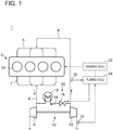
- FIG. 1 is an overall configuration diagram of an engine system including an intake bypass device according to the first embodiment of the present invention.
- the engine system 1 of the present embodiment at least includes an engine body 2, an intake channel 4 for supplying intake air to cylinders 2a of the engine body 2, an exhaust channel 6 for carrying exhaust gas discharged from the cylinders 2a of the engine body 2, a turbocharger 12 for compressing intake air to be supplied to the engine body 2, and an intake bypass device 20 for guiding a part of the compressed intake air compressed by the turbocharger 12 to the exhaust channel 6 bypassing the engine body 2.
- the engine body 2 includes a plurality of cylinders 2a.
- the engine body 2 and the intake channel 4 are connected to each other via an intake manifold 5, and the intake manifold 5 distributes the intake air flowing through the intake channel 4 to each of the plurality of cylinders 2a.
- the engine body 2 and the exhaust channel 6 are connected to each other via an exhaust manifold 7, and the exhaust manifold 7 collects the exhaust air discharged from the plurality of cylinders 2a into the exhaust channel 6.
- the turbocharger 12 includes a turbine 8 disposed in the exhaust channel 6, and a compressor 10 disposed in the intake channel 4 and coupled to the turbine 8 via a rotor to be driven coaxially with the turbine 8.
- the turbine 8 is driven by exhaust energy of the exhaust gas discharged from the engine body 2, and thereby the compressor 10 is coaxially driven, so as to compress the intake air flowing through the intake channel 4.
- an airflow meter 31 for measuring an intake flow rate is disposed on the upstream side of the compressor 10 of the intake channel 4. Further, on the downstream side of the compressor 10 of the intake channel 4, a pressure sensor 33 for measuring a boost pressure of the compressed intake air is disposed.
- the intake bypass device 20 includes a bypass channel 14 connecting the downstream side of the compressor 10 in the intake channel 4 and the upstream side of the turbine 8 in the exhaust channel 6, a bypass valve 16 disposed in the bypass channel 14, and a heating unit 18 for heating the compressed intake air flowing through the bypass channel 14.
- the bypass valve 16 of the present embodiment is configured as a flow-rate control valve for controlling the flow rate of the compressed intake air guided to flow to the exhaust channel 6 from the intake channel 4.
- the valve opening degree of the bypass valve 16 is controlled by a turbo ECU (turbo control unit) 24 described below, so that surging does not occur in the compressor 10.
- the type of the bypass valve 16 is not limited to a flow-rate control valve. It is sufficient if the bypass valve 16 can at least prevent a backward flow of the exhaust gas from the exhaust channel 6 to the intake channel 4, and the bypass valve 16 may be a check valve or the like.
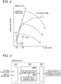
- FIG. 2 is a compressor map showing the operation characteristics of a compressor.
- x-axis is the flow rate and y-axis is the pressure ratio of the pressure at the inlet to that at the outlet of the compressor 10.
- the reference signs N1, N2, N3 in the drawing each represent the rotation speed of the compressor.
- the operating point PI when the compressor 10 is operating at a small flow rate and at a high pressure ratio, the operating point PI may shift to the left side of the surge line to enter the surge region.
- the operating point (operation line) of the compressor 10 entering the surge region represents occurrence of surging in the compressor 10.
- the bypass valve 16 is controlled to have a large valve-opening degree, to increase the flow rate of the compressed intake air guided to flow to the exhaust channel 6 from the intake channel 4.
- the turbine output increases and the operation flow rate of the compressor 10 increases (Q1 to Q2), and thereby the operation point P2 shifts out of the surge region.
- surging is prevented.
- FIG. 3 is a block diagram for describing the function of a turbo ECU.
- the turbo ECU 24 is a control unit independent from an engine electronic control unit (ECU) 22 for controlling the operation state of the engine body 2, and includes a control part 24B and a signal input part 24A separate and independent from the engine ECU 22.
- the turbo ECU 24 and the engine ECU 22 are configured as a microcomputer including a central processing unit (CPU), a random access memory (RAM), a read only memory (ROM), and an I/O interface.
- the turbo ECU 24 includes the signal input part 24A, the turbo control part 24B, and a signal output part 24C.
- signals related to an intake flow rate measured by the airflow meter 31 and a boost pressure measured by the pressure sensor 33 are inputted.
- the turbo control part 24B includes an operation-point computing part 24B1 and a bypass-valve control part 24B2.
- the operation-point computing part 24B1 computes the operation point of the compressor 10 from the compressor map illustrated in FIG. 2 , from the intake flow rate and the boost pressure inputted into the signal input part 24A.
- the bypass-valve control part 24B2 generates a bypass-valve opening degree command value such that increases the valve opening degree of the bypass valve 16, when the operation point computed by the operation-point computing part 24B1 is in the vicinity of the surge region.
- the signal related to the generated bypass-valve opening degree command value is outputted to the bypass valve 16 from the signal output part 24C, and thereby the valve opening degree of the bypass valve 16 is controlled.
- the control logic and hardware configuration of the engine ECU 22 have become increasingly complicated.
- the bypass-valve control part 24B2 for controlling the valve opening degree of the bypass valve 16 is mounted to the engine ECU 22, the control logic and hardware configuration of the engine ECU 22 would become even more complicated.
- communication delay of the engine ECU may be a problem.
- the turbo ECU 24 itself computes the operation point of the compressor 10 and controls the valve opening degree of the bypass valve 16 on the basis of the computed operation point, it is possible to control the bypass valve 16 quickly while avoiding an influence of communication delay as compared to a case where the engine ECU 22 controls the valve opening degree of the bypass valve 16.
- the heating unit 18 is to heat the compressed intake air flowing through the bypass channel 14.
- a heater may be provided, for instance, to be used as a heat source, or exhaust gas discharged from the engine body 2 may be used as a heat source as in the embodiments described below.
- the intake bypass device 20 includes the heating unit 18 for heating the compressed intake air flowing through the bypass channel 14, and is configured so that the compressed intake air having been heated is guided to flow to the upstream side of the turbine 8.
- the heating unit 18 for heating the compressed intake air flowing through the bypass channel 14, and is configured so that the compressed intake air having been heated is guided to flow to the upstream side of the turbine 8.
- FIG. 4 is an overall configuration diagram of an engine system including an intake bypass device according to the second embodiment of the present invention.
- the engine system 1a of the present embodiment basically has a similar configuration to that of the engine system 1 of the above described embodiment, except for the above described heating unit 18.
- the same components are associated with the same reference numerals and not described in detail.
- FIG. 5 is a schematic cross-sectional view illustrating an example of a heating unit of the second embodiment.
- the heating unit 18 of the embodiment illustrated in FIGs. 5A and 5B is constituted by a turbine housing 8A of the turbine 8 forming at least a part of an inner wall surface of the bypass channel 14, at least in a partial section of the bypass channel 14.
- a part of an outer wall surface of a scroll portion 8a forming a scroll channel 8d forms a part of the inner wall surface of the bypass channel 14.
- the part of the outer wall surface of the scroll portion 8a indicated by the reference numeral 14a in the drawing corresponds to the heating unit 18 of the present embodiment.
- a through hole formed inside a shroud portion 8e of the turbine housing 8A constitutes the bypass channel 14, and an inner section of the shroud portion 8e of the turbine housing 8A forms the inner wall surface of the bypass channel 14.
- the entire inner wall surface indicated by the reference numeral 14a in the drawing corresponds to the heating unit 18 of the present embodiment.
- the reference numeral 8b indicates a hub
- 8c indicates an impeller
- 9 indicates a bearing housing.
- FIG. 6 is a schematic cross-sectional view illustrating another example of a heating unit of the second embodiment.
- a part of the turbine housing 8A has a dual structure including an inner housing 8A1 formed of sheet metal forming the scroll channel 8d and an outer housing 8A2 formed of sheet metal covering the inner housing 8A1.
- the space defined by the inner housing 8A1 and the outer housing 8A2 forms a partial section of the above described bypass channel 14.
- an outer wall surface of the inner housing 8A1 forms a part of the inner wall surface of the bypass channel 14, and the outer wall surface (indicated by the reference numeral 14a in the drawing) of the inner housing 8A1 corresponds to the heating unit 18 of the present embodiment.
- the space defined by the inner housing 8A1 and the outer housing 8A2 constitutes a partial section of the above described bypass channel, and the compressed intake air flows through this space, which makes it possible to heat the compressed intake air and cool the turbine housing 8A efficiently.
- FIG. 7 is an overall configuration diagram of an engine system including an intake bypass device according to the third embodiment of the present invention.
- the engine system 1b of the present embodiment further includes an exhaust-gas purification device 26 for purifying exhaust gas discharged from the engine body 2.
- the exhaust-gas purification device 26 is disposed on the downstream side of the turbine 8 in the exhaust channel 6.
- the above described heating unit 18 is disposed on the downstream side of the exhaust-gas purification device 26.
- the engine system 1b of the present embodiment has a similar configuration to that of the above described embodiment, and thus the same components are associated with the same reference numerals and not described in detail.
- FIG. 8 is a schematic cross-sectional view illustrating an example of a heating unit of the third embodiment.
- the heating unit 18 of the embodiment illustrated in FIG. 8 is constituted by a part of an outer surface of an exhaust duct 6a of the exhaust channel 6 at the downstream side of the exhaust-gas purification device 26 forming at least a part of the inner wall surface of the bypass channel 14, in a partial section of the bypass channel 14.
- the part of the outer surface of the exhaust duct 6a indicated by the reference numeral 14a in the drawing corresponds to the heating unit 18 of the present embodiment.
- FIG. 9 is a schematic cross-sectional view illustrating another example of a heating unit of the third embodiment.
- the exhaust channel 6 at the downstream side of the exhaust-gas purification device 26 has a dual structure including an inner exhaust duct 6b through which the exhaust gas flows and an outer exhaust duct 6c covering the inner exhaust duct.
- the space defined by the inner exhaust duct 6b and the outer exhaust duct 6c forms a partial section of the above described bypass channel 14.
- an outer surface of the inner exhaust duct 6b forms a part of the inner wall surface of the bypass channel 14, and the outer surface (indicated by the reference numeral 14a in the drawing) of the inner exhaust duct 6b corresponds to the heating unit 18 of the present embodiment.
- the space defined by the inner exhaust duct 6b and the outer exhaust duct 6c constitutes a partial section of the above described bypass channel, and the compressed intake air flows through this space, which makes it possible to heat the compressed intake air efficiently.
- FIG. 10 is an overall configuration diagram of an engine system including an intake bypass device according to a reference embodiment.
- the engine system 1c of the present embodiment basically has a similar configuration to that of the engine system 1 of the above described embodiment, except for the above described heating unit 18.
- the same components are associated with the same reference numerals and not described in detail.
- FIG. 11 is a schematic cross-sectional view illustrating an example of a heating unit of the reference embodiment.
- the heating unit 18 of the reference embodiment illustrated in FIG. 11 is constituted by a part of an outer wall surface of an exhaust manifold 7 forming a part of the inner wall surface of the bypass channel 14, in a partial section of the bypass channel 14.
- the part of the outer surface of the exhaust manifold 7 indicated by the reference numeral 14a in the drawing corresponds to the heating unit 18 of the present embodiment.
- FIG. 12 is a schematic cross-sectional view illustrating another example of a heating unit of the reference embodiment.
- the exhaust manifold 7 has a dual structure including an inner exhaust manifold 7a through which the exhaust gas flows and an outer exhaust manifold 7b covering the inner exhaust manifold 7a.
- the space defined by the inner exhaust manifold 7a and the outer exhaust manifold 7b forms a partial section of the above described bypass channel 14.
- an outer surface of the inner exhaust manifold 7a forms a part of the inner wall surface of the bypass channel 14, and the outer surface (indicated by the reference numeral 14a in the drawing) of the inner exhaust manifold 7a corresponds to the heating unit 18 of the present embodiment.
- the space defined by the inner exhaust manifold 7a and the outer exhaust manifold 7b constitutes a partial section of the above described bypass channel 14, and the compressed intake air flows through this space, which makes it possible to heat the compressed intake air and cool the exhaust manifold 7 efficiently.
- At least one embodiment of the present invention can be suitably used in an engine including a turbocharger for not only automobiles but also for ships and other industrial usages.
Landscapes
- Engineering & Computer Science (AREA)
- Chemical & Material Sciences (AREA)
- Mechanical Engineering (AREA)
- General Engineering & Computer Science (AREA)
- Combustion & Propulsion (AREA)
- Chemical Kinetics & Catalysis (AREA)
- Health & Medical Sciences (AREA)
- Toxicology (AREA)
- Sustainable Development (AREA)
- Life Sciences & Earth Sciences (AREA)
- Physics & Mathematics (AREA)
- Fluid Mechanics (AREA)
- General Chemical & Material Sciences (AREA)
- Computer Hardware Design (AREA)
- Microelectronics & Electronic Packaging (AREA)
- Supercharger (AREA)
Claims (5)
- Motorsystem (1, 1a, 1c), umfassend:eine Motorkörper (2);einen Einlasskanal (4) zum Zuführen von Einlassluft zu dem Motorkörper (2);einen Abgaskanal (6), durch den das aus dem Motorkörper (2) austretende Abgas strömt;einen Turbolader (12) mit einer Turbine (8), die in dem Abgaskanal (6) angeordnet ist und durch die Energie des aus dem Motorkörper (2) abgegebenen Abgases angetrieben wird, und einem Verdichter (10), der in dem Einlasskanal (4) angeordnet ist und koaxial zu der Turbine (8) angetrieben wird; undeine Einlass-Überbrückungsvorrichtung (20) zum Führen eines Teils der Druckluft, die durch den Verdichter (10) komprimiert wird, um zu einer stromaufwärts gelegenen Seite der Turbine (8) zu strömen unter Überbrückung des Motorkörpers (2),wobei die Einlass-Überbrückungsvorrichtung (20) beinhaltet:einen Überbrückungskanal (14), der eine stromabwärtige Seite des Verdichters (10) im Einlasskanal (4) und eine stromaufwärtige Seite der Turbine (8) im Abgaskanal (6) verbindet,ein Überbrückungsventil (16), das im Überbrückungskanal (14) angeordnet ist und eingerichtet ist, um einen Strom der Druckluft in dem Überbrückungskanal (14) zu steuern, undeine Heizeinheit (18) zum Erwärmen der durch den Überbrückungskanal (14) strömenden Druckluft, wobei die Heizeinheit (18) auf einer stromabwärts gelegenen Seite des Überbrückungsventils (16) im Überbrückungskanal angeordnet ist,wobei die Heizeinheit (18) eingerichtet ist, um das Abgas, das aus dem Motorkörper (2) abgegeben wird, als eine Wärmequelle zum Erwärmen der durch den Überbrückungskanal (14) strömenden komprimierten Einlassluft zu nutzen, dadurch gekennzeichnet, dass die Heizeinheit (18) ein Turbinengehäuse (8A) der Turbine (8) umfasst, das mindestens einen Teil einer inneren Wandfläche des Überbrückungskanals (14) in einem Teilabschnitt des Überbrückungskanals ausbildet.
- Motorsystem gemäß Anspruch 1,
wobei mindestens ein Teil des Turbinengehäuses (8A) eine Doppelstruktur aufweist, die ein aus Blech gebildetes Innengehäuse (8A1) und ein aus Blech gebildetes Außengehäuse (8A2), das das Innengehäuse abdeckt, beinhaltet, und ein Raum, der durch das Innengehäuse und das Außengehäuse definiert ist, einen Teilabschnitt des Überbrückungskanals (14) bildet. - Motorsystem gemäß Anspruch 1,
wobei die Einlass-Überbrückungsvorrichtung (20) eine Turbosteuereinheit (24) beinhaltet, die einen Steuerteil und einen Signaleingangsteil getrennt und unabhängig von einer Motorsteuereinheit (22) zum Steuern eines Betriebszustandes des Motorkörpers (2) beinhaltet, und die Turbosteuereinheit einen Überbrückungsventil-Steuerteil zum Steuern eines Ventilöffnungsgrades des Überbrückungsventils beinhaltet. - Motorsystem gemäß Anspruch 3,
wobei die Turbosteuereinheit (24) beinhaltet:einen Turbosignaleingangsteil, in das ein Sensorsignal eingegeben wird, das sich auf einen Betriebszustand des Motors bezieht, undeinen Turbosteuerteil, das einen Betriebspunkt-Berechnungsteil und den Überbrückungsventil-Steuerteil beinhaltet, wobei der Betriebspunkt-Berechnungsteil eingerichtet ist, um einen Betriebspunkt des Verdichters auf der Grundlage des Sensorsignals zu berechnen, das in den Turbosignaleingangsteil eingegeben wird,wobei der Überbrückungsventil-Steuerteil eingerichtet ist, um den Ventilöffnungsgrad des Überbrückungsventils zu steuern, um zu vergrößern, wenn sich der von dem Betriebspunkt-Berechnungsteil berechnete Betriebspunkt in der Nähe eines Surge-Bereichs befindet. - Das Motorensystem gemäß Anspruch 4,
wobei das Sensorsignal ein Sensorsignal umfasst, das sich auf einen Ladedruck der durch den Kompressor (10) verdichteten Einlassluft und eine Einlass-Durchflussmenge der durch den Kompressor (10) strömenden Druckluft bezieht.
Applications Claiming Priority (1)
| Application Number | Priority Date | Filing Date | Title |
|---|---|---|---|
| PCT/JP2013/077786 WO2015052837A1 (ja) | 2013-10-11 | 2013-10-11 | 吸気バイパス装置を備えたエンジンシステム |
Publications (3)
| Publication Number | Publication Date |
|---|---|
| EP3020939A1 EP3020939A1 (de) | 2016-05-18 |
| EP3020939A4 EP3020939A4 (de) | 2016-10-26 |
| EP3020939B1 true EP3020939B1 (de) | 2019-12-04 |
Family
ID=52812684
Family Applications (1)
| Application Number | Title | Priority Date | Filing Date |
|---|---|---|---|
| EP13895188.4A Active EP3020939B1 (de) | 2013-10-11 | 2013-10-11 | Motorsystem mit einlass-bypassvorrichtung |
Country Status (5)
| Country | Link |
|---|---|
| US (1) | US9797320B2 (de) |
| EP (1) | EP3020939B1 (de) |
| JP (1) | JP6072277B2 (de) |
| CN (1) | CN105324558B (de) |
| WO (1) | WO2015052837A1 (de) |
Families Citing this family (13)
| Publication number | Priority date | Publication date | Assignee | Title |
|---|---|---|---|---|
| EP3121432B1 (de) * | 2014-03-20 | 2019-08-07 | Nissan Motor Co., Ltd | Steuerungsvorrichtung und steuerungsverfahren für dieselmotor |
| FR3035443B1 (fr) * | 2015-04-21 | 2017-04-21 | Ifp Energies Now | Dispositif ameliore de controle de la quantite d'air introduit a l'admission d'un moteur a combustion interne suralimente et procede utilisant un tel dispositif |
| DK178780B1 (en) * | 2015-06-19 | 2017-01-23 | Man Diesel & Turbo Filial Af Man Diesel & Turbo Se Tyskland | Large two-stroke turbocharged compression ignited internal combustion engine with an exhaust gas purification system |
| EP3176397A1 (de) * | 2015-12-04 | 2017-06-07 | Winterthur Gas & Diesel Ltd. | Verbrennungsmotor und verfahren zum optimieren der abgasnachbehandlung eines verbrennungsmotors |
| EP3176396A1 (de) * | 2015-12-04 | 2017-06-07 | Winterthur Gas & Diesel Ltd. | Verbrennungsmotor und verfahren zum optimieren eine abgasnachbehandlung |
| FR3051225B1 (fr) * | 2016-05-11 | 2019-09-13 | IFP Energies Nouvelles | Methode de controle de la quantite d'air introduit a l'admission d'un moteur a combustion interne suralimente par un turbocompresseur a simple entree |
| DK201670345A1 (en) * | 2016-05-24 | 2017-12-11 | Man Diesel & Turbo Filial Af Man Diesel & Turbo Se Tyskland | Method for operating a two-stroke engine system |
| US10934979B2 (en) * | 2017-05-30 | 2021-03-02 | Ford Global Technologies, Llc | Methods and system diagnosing a variable geometry compressor for an internal combustion engine |
| AT522942A2 (de) * | 2019-12-16 | 2021-03-15 | Avl List Gmbh | Brennkraftmaschine |
| DE102020004716B8 (de) * | 2020-08-05 | 2022-06-09 | Mercedes-Benz Group AG | Verbrennungskraftmaschine für ein Kraftfahrzeug sowie Kraftfahrzeug |
| CN114233473B (zh) * | 2021-09-19 | 2025-04-29 | 江鹏 | 一种发动机进气旁通装置 |
| CN114458440B (zh) * | 2021-12-28 | 2023-04-25 | 中国北方发动机研究所(天津) | 一种交叉补燃废气涡轮增压系统 |
| GB2629424A (en) * | 2023-04-28 | 2024-10-30 | Jaguar Land Rover Ltd | Turbomachine housing with heating system inlet and valve |
Citations (1)
| Publication number | Priority date | Publication date | Assignee | Title |
|---|---|---|---|---|
| US20050132705A1 (en) * | 2003-12-18 | 2005-06-23 | Caterpillar Inc. | Engine turbocharger control management system |
Family Cites Families (26)
| Publication number | Priority date | Publication date | Assignee | Title |
|---|---|---|---|---|
| ES390639A1 (es) | 1970-05-02 | 1974-05-01 | Kuehnle Kopp Kausch Ag | Un procedimiento para quitar toxicidad a los gases de esca-pe de motores. |
| US4122673A (en) * | 1973-09-28 | 1978-10-31 | J. Eberspacher | Internal combustion engine with afterburning and catalytic reaction in a supercharger turbine casing |
| FR2478736A1 (fr) * | 1980-03-21 | 1981-09-25 | Semt | Procede et systeme de generation de puissance par moteur a combustion interne suralimente |
| JP2527559B2 (ja) * | 1987-06-16 | 1996-08-28 | ヤマハ発動機株式会社 | タ−ボ過給式エンジン |
| DE3818230A1 (de) | 1988-05-28 | 1989-12-07 | Johann Wimmer | Aggregat zur steigerung des ladedruckes an aufgeladenen verbrennungsmotoren, im teillast- und unteren drehzahlbereich |
| JP2921434B2 (ja) * | 1995-03-24 | 1999-07-19 | トヨタ自動車株式会社 | 車両用縦置き式エンジンの冷却構造 |
| US6003315A (en) * | 1997-03-31 | 1999-12-21 | Caterpillar Inc. | Exhaust gas recirculation system for an internal combustion engine |
| US5987885A (en) | 1998-01-29 | 1999-11-23 | Chrysler Corporation | Combination catalytic converter and heat exchanger that maintains a catalyst substrate within an efficient operating temperature range for emmisions reduction |
| JP2000064844A (ja) | 1998-08-12 | 2000-02-29 | Mitsubishi Heavy Ind Ltd | 内燃機関の過給装置 |
| US6358109B1 (en) * | 1999-12-08 | 2002-03-19 | Bombardier Motor Corporation Of America | Air cooled marine engine exhaust |
| DE10062377B4 (de) * | 2000-12-14 | 2005-10-20 | Siemens Ag | Vorrichtung und Verfahren zum Beheizen eines Abgaskatalysators für eine aufgeladene Brennkraftmaschine |
| JP2004346776A (ja) | 2003-05-20 | 2004-12-09 | Komatsu Ltd | 給気バイパス制御装置を備えた内燃機関 |
| JP4098712B2 (ja) * | 2003-12-25 | 2008-06-11 | 本田技研工業株式会社 | 排気マニホールド一体型エンジンの冷却構造 |
| DE102004009109A1 (de) * | 2004-02-25 | 2005-09-15 | Borgwarner Turbo Systems Gmbh | Verfahren zum Verbinden eines Blechbauteils wie ein Rohr mit einem Gussmetallbauteil wie eine Öffnung eines Gehäuses, insbesondere für Abgasanlage |
| JP4389739B2 (ja) * | 2004-09-29 | 2009-12-24 | 三菱自動車工業株式会社 | 過給機付き内燃機関 |
| SE0501177L (sv) * | 2005-05-25 | 2007-01-25 | Gm Global Tech Operations Inc | Kontrollenhet vid en förbränningsmotor försedd med ett överladdarsystem samt ett system, ett fordon och en metod innefattande en sådan kontrollenhet |
| JP2007085266A (ja) | 2005-09-22 | 2007-04-05 | Toyota Motor Corp | 排気系熱交換装置 |
| JP2007162545A (ja) | 2005-12-13 | 2007-06-28 | Isuzu Motors Ltd | エンジンの過給器システム |
| JP4940927B2 (ja) | 2006-12-15 | 2012-05-30 | トヨタ自動車株式会社 | ターボチャージャの制御装置 |
| JP4803059B2 (ja) | 2007-02-07 | 2011-10-26 | トヨタ自動車株式会社 | 内燃機関のシリンダヘッド |
| JP2010038201A (ja) | 2008-08-01 | 2010-02-18 | Aisan Ind Co Ltd | 中空流体通路部品及びその製造方法 |
| US8677751B2 (en) * | 2009-07-24 | 2014-03-25 | Vandyne Superturbo, Inc. | Rich fuel mixture super-turbocharged engine system |
| US8042335B2 (en) * | 2010-06-03 | 2011-10-25 | Ford Global Technologies, Llc | Intake air heating and exhaust cooling |
| DK177388B1 (en) | 2011-01-31 | 2013-03-04 | Man Diesel & Turbo Deutschland | Large turbocharged two-stroke diesel engine with exhaust gas recirculation |
| US8627662B2 (en) * | 2011-10-19 | 2014-01-14 | General Electric Company | Exhaust gas recirculation heat recovery system and method |
| JP5903917B2 (ja) | 2012-02-08 | 2016-04-13 | トヨタ自動車株式会社 | 内燃機関の冷却装置 |
-
2013
- 2013-10-11 EP EP13895188.4A patent/EP3020939B1/de active Active
- 2013-10-11 CN CN201380077737.7A patent/CN105324558B/zh not_active Expired - Fee Related
- 2013-10-11 JP JP2015541405A patent/JP6072277B2/ja not_active Expired - Fee Related
- 2013-10-11 US US14/911,591 patent/US9797320B2/en not_active Expired - Fee Related
- 2013-10-11 WO PCT/JP2013/077786 patent/WO2015052837A1/ja not_active Ceased
Patent Citations (1)
| Publication number | Priority date | Publication date | Assignee | Title |
|---|---|---|---|---|
| US20050132705A1 (en) * | 2003-12-18 | 2005-06-23 | Caterpillar Inc. | Engine turbocharger control management system |
Also Published As
| Publication number | Publication date |
|---|---|
| CN105324558B (zh) | 2018-10-09 |
| US9797320B2 (en) | 2017-10-24 |
| EP3020939A4 (de) | 2016-10-26 |
| EP3020939A1 (de) | 2016-05-18 |
| JP6072277B2 (ja) | 2017-02-01 |
| US20160215712A1 (en) | 2016-07-28 |
| WO2015052837A1 (ja) | 2015-04-16 |
| CN105324558A (zh) | 2016-02-10 |
| JPWO2015052837A1 (ja) | 2017-03-09 |
Similar Documents
| Publication | Publication Date | Title |
|---|---|---|
| EP3020939B1 (de) | Motorsystem mit einlass-bypassvorrichtung | |
| US8522547B2 (en) | Exhaust gas turbocharger for an internal combustion engine of a motor vehicle | |
| JP5853403B2 (ja) | 内燃機関の制御装置 | |
| CN105822379B (zh) | 发动机制动装置和用于操作发动机制动装置的方法 | |
| CN101675223A (zh) | 控制涡轮增压器的方法 | |
| US20120192557A1 (en) | Engine System | |
| JP2010516945A (ja) | 燃焼機関吸排気システム用の補助空気システム | |
| CN103930656A (zh) | 窜气换气装置 | |
| CN103392058A (zh) | 多级涡轮增压器安排 | |
| JP2013515207A (ja) | 内燃機関 | |
| US20120152214A1 (en) | Turbocharger system | |
| EP2843235B1 (de) | Strukturell asymmetrisches doppelflutiges Turboladerrad | |
| US9546569B2 (en) | Turbocharger with cooled turbine housing, cooled bearing housing, and a common coolant supply | |
| CN102562264A (zh) | 用于运行具有两个涡轮增压器的汽车的方法 | |
| JP5596709B2 (ja) | タービン効率をコントロールするための方法および装置 | |
| CN103032108A (zh) | 用于涡轮机的流控制模块 | |
| CN105705745B (zh) | 排气结构 | |
| CN103195555B (zh) | 用于超涡轮增压发动机的控制系统和方法 | |
| KR101472910B1 (ko) | 볼텍스 튜브를 이용한 흡입공기 냉각장치 | |
| JP2013047523A (ja) | プレッシャウェーブスーパーチャージャを備えた内燃機関における過給圧調整方法 | |
| JP2010138787A (ja) | 内燃機関のegr装置 | |
| CN1982670A (zh) | 双级增压系统 | |
| CN102220896A (zh) | 增压内燃机进气的装置、交通工具和增压内燃机进气的方法 | |
| JP5964260B2 (ja) | エンジンの排ガスエネルギー回収装置 | |
| CN106050401B (zh) | 具有双流道涡轮机和分组汽缸的增压内燃发动机 |
Legal Events
| Date | Code | Title | Description |
|---|---|---|---|
| PUAI | Public reference made under article 153(3) epc to a published international application that has entered the european phase |
Free format text: ORIGINAL CODE: 0009012 |
|
| 17P | Request for examination filed |
Effective date: 20160210 |
|
| AK | Designated contracting states |
Kind code of ref document: A1 Designated state(s): AL AT BE BG CH CY CZ DE DK EE ES FI FR GB GR HR HU IE IS IT LI LT LU LV MC MK MT NL NO PL PT RO RS SE SI SK SM TR |
|
| AX | Request for extension of the european patent |
Extension state: BA ME |
|
| A4 | Supplementary search report drawn up and despatched |
Effective date: 20160922 |
|
| RIC1 | Information provided on ipc code assigned before grant |
Ipc: F01N 5/02 20060101ALI20160916BHEP Ipc: F01D 25/26 20060101ALI20160916BHEP Ipc: F02B 33/00 20060101AFI20160916BHEP Ipc: F01N 3/02 20060101ALI20160916BHEP Ipc: F01D 25/12 20060101ALI20160916BHEP Ipc: F02B 39/00 20060101ALI20160916BHEP Ipc: F01N 3/05 20060101ALI20160916BHEP Ipc: F02B 37/16 20060101ALI20160916BHEP Ipc: F01N 3/28 20060101ALI20160916BHEP Ipc: F02B 37/20 20060101ALI20160916BHEP Ipc: F01D 25/14 20060101ALI20160916BHEP |
|
| DAX | Request for extension of the european patent (deleted) | ||
| STAA | Information on the status of an ep patent application or granted ep patent |
Free format text: STATUS: EXAMINATION IS IN PROGRESS |
|
| 17Q | First examination report despatched |
Effective date: 20181018 |
|
| RIC1 | Information provided on ipc code assigned before grant |
Ipc: F01D 25/12 20060101ALI20190220BHEP Ipc: F02B 37/20 20060101ALI20190220BHEP Ipc: F02B 37/16 20060101AFI20190220BHEP Ipc: F01N 3/05 20060101ALI20190220BHEP |
|
| REG | Reference to a national code |
Ref country code: DE Ref legal event code: R079 Ref document number: 602013063769 Country of ref document: DE Free format text: PREVIOUS MAIN CLASS: F02B0033000000 Ipc: F02B0037160000 |
|
| GRAP | Despatch of communication of intention to grant a patent |
Free format text: ORIGINAL CODE: EPIDOSNIGR1 |
|
| STAA | Information on the status of an ep patent application or granted ep patent |
Free format text: STATUS: GRANT OF PATENT IS INTENDED |
|
| RIC1 | Information provided on ipc code assigned before grant |
Ipc: F02B 37/16 20060101AFI20190709BHEP Ipc: F01D 25/12 20060101ALI20190709BHEP Ipc: F02C 9/18 20060101ALI20190709BHEP Ipc: F01D 17/10 20060101ALI20190709BHEP Ipc: F01N 3/05 20060101ALI20190709BHEP Ipc: F02B 37/20 20060101ALI20190709BHEP Ipc: F02C 6/12 20060101ALI20190709BHEP Ipc: F02B 39/00 20060101ALI20190709BHEP |
|
| INTG | Intention to grant announced |
Effective date: 20190730 |
|
| GRAS | Grant fee paid |
Free format text: ORIGINAL CODE: EPIDOSNIGR3 |
|
| GRAA | (expected) grant |
Free format text: ORIGINAL CODE: 0009210 |
|
| STAA | Information on the status of an ep patent application or granted ep patent |
Free format text: STATUS: THE PATENT HAS BEEN GRANTED |
|
| AK | Designated contracting states |
Kind code of ref document: B1 Designated state(s): AL AT BE BG CH CY CZ DE DK EE ES FI FR GB GR HR HU IE IS IT LI LT LU LV MC MK MT NL NO PL PT RO RS SE SI SK SM TR |
|
| REG | Reference to a national code |
Ref country code: GB Ref legal event code: FG4D |
|
| REG | Reference to a national code |
Ref country code: CH Ref legal event code: EP |
|
| REG | Reference to a national code |
Ref country code: AT Ref legal event code: REF Ref document number: 1209680 Country of ref document: AT Kind code of ref document: T Effective date: 20191215 |
|
| REG | Reference to a national code |
Ref country code: DE Ref legal event code: R096 Ref document number: 602013063769 Country of ref document: DE |
|
| REG | Reference to a national code |
Ref country code: IE Ref legal event code: FG4D |
|
| REG | Reference to a national code |
Ref country code: NL Ref legal event code: FP |
|
| REG | Reference to a national code |
Ref country code: LT Ref legal event code: MG4D |
|
| PG25 | Lapsed in a contracting state [announced via postgrant information from national office to epo] |
Ref country code: FI Free format text: LAPSE BECAUSE OF FAILURE TO SUBMIT A TRANSLATION OF THE DESCRIPTION OR TO PAY THE FEE WITHIN THE PRESCRIBED TIME-LIMIT Effective date: 20191204 Ref country code: BG Free format text: LAPSE BECAUSE OF FAILURE TO SUBMIT A TRANSLATION OF THE DESCRIPTION OR TO PAY THE FEE WITHIN THE PRESCRIBED TIME-LIMIT Effective date: 20200304 Ref country code: LT Free format text: LAPSE BECAUSE OF FAILURE TO SUBMIT A TRANSLATION OF THE DESCRIPTION OR TO PAY THE FEE WITHIN THE PRESCRIBED TIME-LIMIT Effective date: 20191204 Ref country code: GR Free format text: LAPSE BECAUSE OF FAILURE TO SUBMIT A TRANSLATION OF THE DESCRIPTION OR TO PAY THE FEE WITHIN THE PRESCRIBED TIME-LIMIT Effective date: 20200305 Ref country code: NO Free format text: LAPSE BECAUSE OF FAILURE TO SUBMIT A TRANSLATION OF THE DESCRIPTION OR TO PAY THE FEE WITHIN THE PRESCRIBED TIME-LIMIT Effective date: 20200304 Ref country code: SE Free format text: LAPSE BECAUSE OF FAILURE TO SUBMIT A TRANSLATION OF THE DESCRIPTION OR TO PAY THE FEE WITHIN THE PRESCRIBED TIME-LIMIT Effective date: 20191204 Ref country code: LV Free format text: LAPSE BECAUSE OF FAILURE TO SUBMIT A TRANSLATION OF THE DESCRIPTION OR TO PAY THE FEE WITHIN THE PRESCRIBED TIME-LIMIT Effective date: 20191204 |
|
| PG25 | Lapsed in a contracting state [announced via postgrant information from national office to epo] |
Ref country code: HR Free format text: LAPSE BECAUSE OF FAILURE TO SUBMIT A TRANSLATION OF THE DESCRIPTION OR TO PAY THE FEE WITHIN THE PRESCRIBED TIME-LIMIT Effective date: 20191204 Ref country code: RS Free format text: LAPSE BECAUSE OF FAILURE TO SUBMIT A TRANSLATION OF THE DESCRIPTION OR TO PAY THE FEE WITHIN THE PRESCRIBED TIME-LIMIT Effective date: 20191204 |
|
| PG25 | Lapsed in a contracting state [announced via postgrant information from national office to epo] |
Ref country code: AL Free format text: LAPSE BECAUSE OF FAILURE TO SUBMIT A TRANSLATION OF THE DESCRIPTION OR TO PAY THE FEE WITHIN THE PRESCRIBED TIME-LIMIT Effective date: 20191204 |
|
| PG25 | Lapsed in a contracting state [announced via postgrant information from national office to epo] |
Ref country code: EE Free format text: LAPSE BECAUSE OF FAILURE TO SUBMIT A TRANSLATION OF THE DESCRIPTION OR TO PAY THE FEE WITHIN THE PRESCRIBED TIME-LIMIT Effective date: 20191204 Ref country code: RO Free format text: LAPSE BECAUSE OF FAILURE TO SUBMIT A TRANSLATION OF THE DESCRIPTION OR TO PAY THE FEE WITHIN THE PRESCRIBED TIME-LIMIT Effective date: 20191204 Ref country code: ES Free format text: LAPSE BECAUSE OF FAILURE TO SUBMIT A TRANSLATION OF THE DESCRIPTION OR TO PAY THE FEE WITHIN THE PRESCRIBED TIME-LIMIT Effective date: 20191204 Ref country code: CZ Free format text: LAPSE BECAUSE OF FAILURE TO SUBMIT A TRANSLATION OF THE DESCRIPTION OR TO PAY THE FEE WITHIN THE PRESCRIBED TIME-LIMIT Effective date: 20191204 Ref country code: PT Free format text: LAPSE BECAUSE OF FAILURE TO SUBMIT A TRANSLATION OF THE DESCRIPTION OR TO PAY THE FEE WITHIN THE PRESCRIBED TIME-LIMIT Effective date: 20200429 |
|
| PG25 | Lapsed in a contracting state [announced via postgrant information from national office to epo] |
Ref country code: SM Free format text: LAPSE BECAUSE OF FAILURE TO SUBMIT A TRANSLATION OF THE DESCRIPTION OR TO PAY THE FEE WITHIN THE PRESCRIBED TIME-LIMIT Effective date: 20191204 Ref country code: IS Free format text: LAPSE BECAUSE OF FAILURE TO SUBMIT A TRANSLATION OF THE DESCRIPTION OR TO PAY THE FEE WITHIN THE PRESCRIBED TIME-LIMIT Effective date: 20200404 Ref country code: SK Free format text: LAPSE BECAUSE OF FAILURE TO SUBMIT A TRANSLATION OF THE DESCRIPTION OR TO PAY THE FEE WITHIN THE PRESCRIBED TIME-LIMIT Effective date: 20191204 |
|
| REG | Reference to a national code |
Ref country code: DE Ref legal event code: R097 Ref document number: 602013063769 Country of ref document: DE |
|
| REG | Reference to a national code |
Ref country code: AT Ref legal event code: MK05 Ref document number: 1209680 Country of ref document: AT Kind code of ref document: T Effective date: 20191204 |
|
| PLBE | No opposition filed within time limit |
Free format text: ORIGINAL CODE: 0009261 |
|
| STAA | Information on the status of an ep patent application or granted ep patent |
Free format text: STATUS: NO OPPOSITION FILED WITHIN TIME LIMIT |
|
| PG25 | Lapsed in a contracting state [announced via postgrant information from national office to epo] |
Ref country code: DK Free format text: LAPSE BECAUSE OF FAILURE TO SUBMIT A TRANSLATION OF THE DESCRIPTION OR TO PAY THE FEE WITHIN THE PRESCRIBED TIME-LIMIT Effective date: 20191204 |
|
| 26N | No opposition filed |
Effective date: 20200907 |
|
| PG25 | Lapsed in a contracting state [announced via postgrant information from national office to epo] |
Ref country code: SI Free format text: LAPSE BECAUSE OF FAILURE TO SUBMIT A TRANSLATION OF THE DESCRIPTION OR TO PAY THE FEE WITHIN THE PRESCRIBED TIME-LIMIT Effective date: 20191204 Ref country code: AT Free format text: LAPSE BECAUSE OF FAILURE TO SUBMIT A TRANSLATION OF THE DESCRIPTION OR TO PAY THE FEE WITHIN THE PRESCRIBED TIME-LIMIT Effective date: 20191204 Ref country code: PL Free format text: LAPSE BECAUSE OF FAILURE TO SUBMIT A TRANSLATION OF THE DESCRIPTION OR TO PAY THE FEE WITHIN THE PRESCRIBED TIME-LIMIT Effective date: 20191204 |
|
| PG25 | Lapsed in a contracting state [announced via postgrant information from national office to epo] |
Ref country code: IT Free format text: LAPSE BECAUSE OF FAILURE TO SUBMIT A TRANSLATION OF THE DESCRIPTION OR TO PAY THE FEE WITHIN THE PRESCRIBED TIME-LIMIT Effective date: 20191204 |
|
| REG | Reference to a national code |
Ref country code: CH Ref legal event code: PL |
|
| PG25 | Lapsed in a contracting state [announced via postgrant information from national office to epo] |
Ref country code: MC Free format text: LAPSE BECAUSE OF FAILURE TO SUBMIT A TRANSLATION OF THE DESCRIPTION OR TO PAY THE FEE WITHIN THE PRESCRIBED TIME-LIMIT Effective date: 20191204 Ref country code: LU Free format text: LAPSE BECAUSE OF NON-PAYMENT OF DUE FEES Effective date: 20201011 |
|
| REG | Reference to a national code |
Ref country code: BE Ref legal event code: MM Effective date: 20201031 |
|
| PG25 | Lapsed in a contracting state [announced via postgrant information from national office to epo] |
Ref country code: LI Free format text: LAPSE BECAUSE OF NON-PAYMENT OF DUE FEES Effective date: 20201031 Ref country code: BE Free format text: LAPSE BECAUSE OF NON-PAYMENT OF DUE FEES Effective date: 20201031 Ref country code: CH Free format text: LAPSE BECAUSE OF NON-PAYMENT OF DUE FEES Effective date: 20201031 |
|
| PG25 | Lapsed in a contracting state [announced via postgrant information from national office to epo] |
Ref country code: IE Free format text: LAPSE BECAUSE OF NON-PAYMENT OF DUE FEES Effective date: 20201011 |
|
| PG25 | Lapsed in a contracting state [announced via postgrant information from national office to epo] |
Ref country code: TR Free format text: LAPSE BECAUSE OF FAILURE TO SUBMIT A TRANSLATION OF THE DESCRIPTION OR TO PAY THE FEE WITHIN THE PRESCRIBED TIME-LIMIT Effective date: 20191204 Ref country code: MT Free format text: LAPSE BECAUSE OF FAILURE TO SUBMIT A TRANSLATION OF THE DESCRIPTION OR TO PAY THE FEE WITHIN THE PRESCRIBED TIME-LIMIT Effective date: 20191204 Ref country code: CY Free format text: LAPSE BECAUSE OF FAILURE TO SUBMIT A TRANSLATION OF THE DESCRIPTION OR TO PAY THE FEE WITHIN THE PRESCRIBED TIME-LIMIT Effective date: 20191204 |
|
| PG25 | Lapsed in a contracting state [announced via postgrant information from national office to epo] |
Ref country code: MK Free format text: LAPSE BECAUSE OF FAILURE TO SUBMIT A TRANSLATION OF THE DESCRIPTION OR TO PAY THE FEE WITHIN THE PRESCRIBED TIME-LIMIT Effective date: 20191204 |
|
| PGFP | Annual fee paid to national office [announced via postgrant information from national office to epo] |
Ref country code: NL Payment date: 20220916 Year of fee payment: 10 Ref country code: GB Payment date: 20220901 Year of fee payment: 10 |
|
| PGFP | Annual fee paid to national office [announced via postgrant information from national office to epo] |
Ref country code: FR Payment date: 20220908 Year of fee payment: 10 |
|
| PGFP | Annual fee paid to national office [announced via postgrant information from national office to epo] |
Ref country code: DE Payment date: 20220621 Year of fee payment: 10 |
|
| REG | Reference to a national code |
Ref country code: DE Ref legal event code: R119 Ref document number: 602013063769 Country of ref document: DE |
|
| REG | Reference to a national code |
Ref country code: NL Ref legal event code: MM Effective date: 20231101 |
|
| GBPC | Gb: european patent ceased through non-payment of renewal fee |
Effective date: 20231011 |
|
| PG25 | Lapsed in a contracting state [announced via postgrant information from national office to epo] |
Ref country code: GB Free format text: LAPSE BECAUSE OF NON-PAYMENT OF DUE FEES Effective date: 20231011 |
|
| PG25 | Lapsed in a contracting state [announced via postgrant information from national office to epo] |
Ref country code: NL Free format text: LAPSE BECAUSE OF NON-PAYMENT OF DUE FEES Effective date: 20231101 |
|
| PG25 | Lapsed in a contracting state [announced via postgrant information from national office to epo] |
Ref country code: NL Free format text: LAPSE BECAUSE OF NON-PAYMENT OF DUE FEES Effective date: 20231101 Ref country code: GB Free format text: LAPSE BECAUSE OF NON-PAYMENT OF DUE FEES Effective date: 20231011 Ref country code: FR Free format text: LAPSE BECAUSE OF NON-PAYMENT OF DUE FEES Effective date: 20231031 Ref country code: DE Free format text: LAPSE BECAUSE OF NON-PAYMENT OF DUE FEES Effective date: 20240501 |