EP0038516A1 - Tube d'image en couleur avec blindage magnétique intérieur - Google Patents
Tube d'image en couleur avec blindage magnétique intérieur Download PDFInfo
- Publication number
- EP0038516A1 EP0038516A1 EP81102858A EP81102858A EP0038516A1 EP 0038516 A1 EP0038516 A1 EP 0038516A1 EP 81102858 A EP81102858 A EP 81102858A EP 81102858 A EP81102858 A EP 81102858A EP 0038516 A1 EP0038516 A1 EP 0038516A1
- Authority
- EP
- European Patent Office
- Prior art keywords
- side sections
- electron beams
- picture tube
- color picture
- inner shield
- Prior art date
- Legal status (The legal status is an assumption and is not a legal conclusion. Google has not performed a legal analysis and makes no representation as to the accuracy of the status listed.)
- Granted
Links
- 230000005291 magnetic effect Effects 0.000 title claims abstract description 32
- 238000010894 electron beam technology Methods 0.000 claims abstract description 52
- OAICVXFJPJFONN-UHFFFAOYSA-N Phosphorus Chemical compound [P] OAICVXFJPJFONN-UHFFFAOYSA-N 0.000 claims abstract description 15
- 238000005452 bending Methods 0.000 claims abstract description 4
- 239000000696 magnetic material Substances 0.000 claims abstract description 4
- 230000005389 magnetism Effects 0.000 abstract description 17
- 239000013598 vector Substances 0.000 abstract description 10
- 239000000306 component Substances 0.000 description 34
- 238000006073 displacement reaction Methods 0.000 description 3
- 230000000694 effects Effects 0.000 description 2
- 230000002542 deteriorative effect Effects 0.000 description 1
- 239000003302 ferromagnetic material Substances 0.000 description 1
- 238000004519 manufacturing process Methods 0.000 description 1
Images



Classifications
-
- H—ELECTRICITY
- H01—ELECTRIC ELEMENTS
- H01J—ELECTRIC DISCHARGE TUBES OR DISCHARGE LAMPS
- H01J29/00—Details of cathode-ray tubes or of electron-beam tubes of the types covered by group H01J31/00
- H01J29/02—Electrodes; Screens; Mounting, supporting, spacing or insulating thereof
- H01J29/06—Screens for shielding; Masks interposed in the electron stream
Definitions
- This invention relates to color picture tube provided with an inner magnetic sheild.
- An object of the invention is to provide a color. picture tube provided with an inner shield which can prevent or minimize the mislanding of the electron beams, particularly at the corners of the face plate, due to the earth magnetism.
- a color picture tube which comprises phosphor stripes provided on the face plate in a regular arrangement and an inner shield made of a magnetic material and provided at the four corners with portions of increased magnetic . reluctance.
- the increased magnetic reluctance portions correspond in locality to the four corners of the face plate where mislanding of the electron beams is most liable to result, and in one embodiment of the invention they are gaps.
- a first subcomponent directed in the direction parallel to the tube axis, a second subcomponent directed in the direction perpendicular to the first subcomponent and substantially parallel to the phosphor .stripes and a third subcomponent directed in the direction perpendicular to the first and second subcomponents are produced from the horizontal component of the earth magnetic field.
- the first, second and third subcomponents produced in the space adjacent to the four corners of the inner shield can be adjusted by adjusting the width and shape of the magnetic reluctance portions, and in effect the magnitude of the electromagnetic forces acting upon the electron beam can be adjusted for preventing the mislanding thereof.
- an embodiment of the color picture tube according to the invention is shown.
- an electron gun assembly 4 for producing three electron beams is received in a neck 2 of the color picture tube, and an adjustment member 6 including a color purity magnet and a convergence yoke are provided on the outer periphery of the neck 2.
- a deflection yoke 10 for deflecting the electron beams is secured to the outer periphery of an yoke section 8 of the tube extending from the neck 2.
- a funnel section 12 extending.from the yoke section 8 has its front opening hermetically sealed with a face plate 14, thus forming a color picture tube envelope which is held evacuated.
- a phosphor layer which is constituted by a number of red, green and blue phosphor stripes respectively emitting red, green and blue light when corresponding electron beams are landed on them, these phosphor stripes being in a parallel and regular arrangement.
- a shadow mask 18 provided with a number of regularly arranged apertures or slits is disposed to face the inner surface of the face plate 14.
- the shadow mask 18 is supported in a substantially rectangular mask frame 20, which is in turn fixed to the face plate 12 via a spring 24 secured to pannel pins 20 part of which are embeded in the face plate 24.
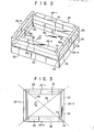
- the inner shield 26 which is made of a magnetic material, preferably a ferro-magnetic material, as shown in Figs. 2 and 3.
- the inner shield 26 is constituted by two long side sections 26-1 and 26-2 having substantially the same shape and corresponding to the long sides of the rectangular mask frame 20 and two short side sections 26-3 and 26-4 also having substantially the same shape and corresponding to the short sides of the mask frame 20.
- the short side sections 26-3 and 26-4 are each formed from a magnetic plate by bending opposite edge portions thereof, and they each have a side portion 28 and front and rear portions 30 and 32 extending from the side portion 28 substantially at right angles thereto and in the-same direction.
- the long side sections 26-1 and 26-2 are each formed from a magnetic plate by bending opposite edge portions thereof, and they each have a side portion 34 and front and rear portions 36 and 38. extending from the side portion 38 substantially at right angles thereto and in the same direction.
- the side portions 28 and 34 of the long and short side sections 26-1, 26-2, 26-3 and 26-4 substantially have the same height H, but the widths W 1 , W 2 , W 3 and W 4 of the rear and front portions 30, 32, 36 and 38 are set to appropriate values as will be described hereinafter.
- the front portions 30 and 36 of the short and long side sections are secured to a rear supporting face 40 of the mask frame 20, with first gaps 42 provided between the side portions 34 of the long side section 26-1 and 26-2 on one hand and the corresponding side portions 28 of the short side sections 26-3 and 26-4 on the other hand and second gaps 44 provided between the rear portions 38 of the long side sections 26-1 and 26-2 on one hand and the corresponding rear portions 32 of the short side sections 26-3 and 26-4 on the other hand.
- the first and second gaps 42 and 44 are found on the diagonals of the mask frame 26, i.e., on the diagonals 46 and 48 of the face plate 14, and the second gaps 44 extend substantially parallel to the short sides of the face plate 14. In any event, the first and second gaps 42 and 44 are provided substantially on the four corners of the face plate 14.
- the inner shield 26 consisting of the four sections 26-1 to 26-4 provided inside the funnel section 12 near the shadow mask 18 such as to surround an electron beam passage space and the gaps 42 and 44 provided in the inner shield 26 at portions thereof corresponding to the four corners of the face plate 14, the mislanding of the electron beams that may otherwise be caused as they are greatly bent by the earth magnetism can be prevented under the following principles.
- the electron beams emitted from the electron gun 4 are deflected by the deflection yoke 10 as they proceed therethrough to be directed through the sapce in the funnel section 12 toward the shadow mask 18, and after passing through the slits or apertures of the shadow mask 18 they land on corresponding phosphor stripes of the phosphor layer 16.
- the extent to which the electron beams are bent by the earth magnetism acting upon these electron beams at various passing points within the funnel section 12 is smaller for electron beams proceeding in directions closer to the center of the shadow mask 18 and is greater for electron beams proceeding in directions closer to the four corners of the shadow mask 18. Also, it is greater in the electron beams passing area closer to the shadow mask 18 and is smaller in the electron beam passing area closer to the deflection yoke 10.
- the inner shield 26 need not magnetically shield the entire inner surface of the funnel section 12 but is required to magnetically shield only the inner surface of the funnel section 12 close to the shadow mask 18.
- the magnetic force lines of the earth magnetism extending from the South pole to the North pole are parallel to the earth surface substantially on the equator while at the South and North poles they are substantially perpendicular to the earth surface. In areas between the equator and each pole, they are inclined with respect to the earth surface and have vertical and holizontal components M z and My perpendicular and parallel to the earth surface respectively.
- the electron beams deflected by the deflection yoke 10 have a current component Eyextending in the direction y of the tube axis, a current component Ex extending in the direction x parallel to the long side of the face plate 14 and perpendicular to the direction y and a current component E z extending in the direction z parallel to the short side of the face plate 14 and perpendicular to the directions x and y.
- the vertical components M z of earth magnetic field vectors are concentrated into the inner shield 26 and pass therethrough, and they hardly pass through the space enclosed within the inner shield 26 as shown in Fig. 4. Thus, within the inner shield 26 the electron beams are rarely displaced by the vertical component M z of the earth magnetism.
- the horizontal components My of the earth magnetism vectors are also concentrated into the inner shield 26 and pass therethrough as shown in Fig. 6.
- no horizontal component of the earth magnetism passes through the space inside the inner shield 26, and the electron beams passing through this space are not displaced by the horizontal component M y.
- the horizontal component My of the earth magnetism passes through the space within the funnel section 12 between the inner shield 26 and deflection yoke 10, the electron beams are not displaced by this horizontal component My so much as to. cause their mislanding.
- the current component Ey of the electron beams passing through the central zone in a direction y is great while its z and x directional current components E z and E x are small so that no external force F is exerted to the electron beams as is obvious from the Fleming's left hand law.
- the electron beams are also not displaced by the horizontal components My. 1 that pass straight through the inner shield 26. This is because the electron beams are not deflected by the deflection yoke 10 up to the area where the horizontal components M y-1 are present. However, in the space close to the inner surface of the inner shield 26, particularly to the corners thereof, the horizontal components My -2 are bent toward the inner shield 26 as shown at 48, 50, 52 and 54 in Figs.
- forces fx and F x are exerted to the electron beams according to the Fleming's law as shown in Fig. 9. While in Fig. 9 the forces f x and F x are shown to be exerted to different points for the sake of the clarity of the illustration, actually they all act upon the same electron beam. Although not shown in Fig. 9, the forces Fy, F z , fy and f z are produced by the current vectors E x , Ey and E z and field vectors m x , my and m z . The forces fy and Fy are directed in the direction of the tube axis, so that they are not effective to cause mislanding of the electron beams.
- the forces f z and F z are directed in the direction parallel to the phosphor stripes and are thus ineffective to cause mislanding of the electron beams. If the force vectors f x and F x are equal in the scalar, they cancel each other, and in this case the mislanding of the electron beams will not result.
- high magnetic reluctance portions i.e., gaps 42 and 44, are provided at the four corners of the inner shield 26.
- the proportions of the scalars of the field subcomponents m x , my and m z of the vectors 48, 50, 52 and 54 that are obtained from the horizontal magnetic field components M y-2 passing through the space near the four corners may be s,uitably selected by appropriately setting the gaps 42 and 44. More particularly, by increasing the gaps 42 and 44 the subcomponent m x and my are reduced while the subcomponent m x is increased. On the other hand, by reducing the gaps 42 and 44 the subcomponents m x and my are increased while the subcomponent m z are reduced.
- the magnitudes of the forces f x and F x may be made equal to prevent the mislanding and improve the color purity at the corners of the f-ace plate 14.
- the electron beams were displaced substantially by 17.5 ⁇ m when the face plate 14 was directed from the South to the North and also turned the same amount when the face plate 14 was directed from the east to the west. This value of displacement was sufficiently small to prevent the mislanding. Also, the displacement was small and equal when the direction of the face plate was changed.
- the gaps 42 and 44 in the inner shield 26 it is possible to adjust the electromagnetic force acting upon the electron beams due to the horizontal component of the earth magnetic field. Also, by suitably selecting the width W 3 of the rear portion 32 of the short side section, it is possible to shield the electron beams against leakage through the gaps 42. Further, by suitably selecting the widths W 3 and W 4 of the rear portions 32 and 38 of the long and short side sections, it is possible to the landing of overdeflected electron beams upon phosphor strips.
- the widths W 1 and W 2 of the front portions 36 and 30 it is possible to shield unnecessary-electron beams adjacent to the effective electron beams, that is, the landing area on the phosphor layer 16 can be defined by the front portions 36 and 30.
- the height H of the side portions 28 and 34 it is possible to prevent the electron beams from being reflected between the front and rear portions 30, 32, 36 and 38 of the inner shield 26.
- the inner shield 26 may be provided with not only the function as a magnetic shield but also the function as an electron shield.
- Fig. 13 shows a different embodiment of the inner shield 56 according to the invention.
- This inner shield 56 is not box-like in shape as shown in Fig. 2, but has a substantially trapezoidal sectional profile.
- this.inner shield 56 includes four sections 56-1, 56-2, 56-3 and 56-4, and gaps 58-1, 58-2, 58-3 and 58-4 are defined by these sections.
- These individual sections of the inner shield 56 extend along the inner surface of the funnel sections 12, so that they have a substantially trapezoidal sectional profile.
- the gaps 58-1 to 58-4 are all provided to be found on the diagonals of the face plate 16 to minimize the effect of the earth magnetism as mentioned earlier.
- this embodiment not only the magnetic field passing through the space inside the funnel sec- .tion 12 in the neighborhood of the shadow mask 18 but also the magnetic field passing through the space in the neighborhood of the deflection yoke 10 can be shielded.
- gaps have been provided as high magnetic reluctance zones at the four corners of the inner shield, these gaps may be replaced with non-magnetic members.
- the inner shield can be assembled from four sections, and in this case it is possible to improve the effeciency of manufacture of the inner shield and reduce the cost thereof.
Landscapes
- Electrodes For Cathode-Ray Tubes (AREA)
Applications Claiming Priority (4)
| Application Number | Priority Date | Filing Date | Title |
|---|---|---|---|
| JP4958480A JPS56147345A (en) | 1980-04-17 | 1980-04-17 | Color picture tube |
| JP49583/80 | 1980-04-17 | ||
| JP4958380A JPS56147344A (en) | 1980-04-17 | 1980-04-17 | Color picture tube |
| JP49584/80 | 1980-04-17 |
Publications (2)
| Publication Number | Publication Date |
|---|---|
| EP0038516A1 true EP0038516A1 (fr) | 1981-10-28 |
| EP0038516B1 EP0038516B1 (fr) | 1984-02-08 |
Family
ID=26390001
Family Applications (1)
| Application Number | Title | Priority Date | Filing Date |
|---|---|---|---|
| EP81102858A Expired EP0038516B1 (fr) | 1980-04-17 | 1981-04-14 | Tube d'image en couleur avec blindage magnétique intérieur |
Country Status (3)
| Country | Link |
|---|---|
| US (1) | US4385256A (fr) |
| EP (1) | EP0038516B1 (fr) |
| DE (1) | DE3162156D1 (fr) |
Cited By (4)
| Publication number | Priority date | Publication date | Assignee | Title |
|---|---|---|---|---|
| EP0118959A1 (fr) * | 1983-03-14 | 1984-09-19 | North American Philips Consumer Electronics Corp. | Tube cathodique |
| GB2208034A (en) * | 1987-08-13 | 1989-02-15 | Ibm | Reducing magnetic radiation in front of a cathode ray tube screen |
| EP0595405A1 (fr) * | 1992-10-28 | 1994-05-04 | Koninklijke Philips Electronics N.V. | Tube à rayons cathodiques couleurs |
| CN103668913A (zh) * | 2012-09-20 | 2014-03-26 | 广东美芝精密制造有限公司 | 热泵干衣机的控制方法 |
Families Citing this family (11)
| Publication number | Priority date | Publication date | Assignee | Title |
|---|---|---|---|---|
| US4556821A (en) * | 1984-03-15 | 1985-12-03 | Rca Corporation | Color image display system having an improved external magnetic shield |
| US4563612A (en) * | 1984-06-25 | 1986-01-07 | Rca Corporation | Cathode-ray tube having antistatic silicate glare-reducing coating |
| GB2190239B (en) * | 1986-05-02 | 1990-02-21 | Philips Electronic Associated | Cathode ray display tube |
| JPH07107831B2 (ja) * | 1986-12-26 | 1995-11-15 | ソニー株式会社 | 陰極線管 |
| JP2544543B2 (ja) * | 1991-06-11 | 1996-10-16 | 東北学院大学 | カラ―陰極線管 |
| JP2762328B2 (ja) * | 1992-07-16 | 1998-06-04 | 東洋鋼鈑株式会社 | インナーシールド用素材およびその製造法 |
| JPH0636701A (ja) * | 1992-07-21 | 1994-02-10 | Tohoku Gakuin Univ | カラー陰極線管 |
| SG98404A1 (en) * | 2000-06-01 | 2003-09-19 | Sony Electronics Singapore Pte | A magnetic shield for a cathode ray tube |
| KR100339365B1 (ko) * | 2000-06-13 | 2002-06-03 | 구자홍 | 음극선관의 텐션 새도우마스크의 조립체 구조 |
| US6710527B2 (en) * | 2000-08-04 | 2004-03-23 | Matsushita Electric Industrial Co., Ltd. | Cathode ray tube with slit in dead space of shadow mask |
| JP5170232B2 (ja) * | 2008-02-28 | 2013-03-27 | 日本電気株式会社 | 電磁シールド構造およびそれを用いた無線装置、電磁シールドの製造方法 |
Citations (2)
| Publication number | Priority date | Publication date | Assignee | Title |
|---|---|---|---|---|
| GB1327364A (en) * | 1970-12-07 | 1973-08-22 | Rca Corp | Cathode ray tubes and shields therefor |
| US4019085A (en) * | 1973-05-02 | 1977-04-19 | Mitsubishi Denki Kabushiki Kaisha | Internal magnetic shield for cathode ray tube |
Family Cites Families (2)
| Publication number | Priority date | Publication date | Assignee | Title |
|---|---|---|---|---|
| JPS5413253A (en) * | 1977-07-01 | 1979-01-31 | Hitachi Ltd | Color receiving tube |
| JPS6032304B2 (ja) * | 1978-02-17 | 1985-07-27 | 日本電気株式会社 | カラ−受像管 |
-
1981
- 1981-04-14 DE DE8181102858T patent/DE3162156D1/de not_active Expired
- 1981-04-14 EP EP81102858A patent/EP0038516B1/fr not_active Expired
- 1981-04-15 US US06/254,492 patent/US4385256A/en not_active Expired - Lifetime
Patent Citations (2)
| Publication number | Priority date | Publication date | Assignee | Title |
|---|---|---|---|---|
| GB1327364A (en) * | 1970-12-07 | 1973-08-22 | Rca Corp | Cathode ray tubes and shields therefor |
| US4019085A (en) * | 1973-05-02 | 1977-04-19 | Mitsubishi Denki Kabushiki Kaisha | Internal magnetic shield for cathode ray tube |
Cited By (5)
| Publication number | Priority date | Publication date | Assignee | Title |
|---|---|---|---|---|
| EP0118959A1 (fr) * | 1983-03-14 | 1984-09-19 | North American Philips Consumer Electronics Corp. | Tube cathodique |
| GB2208034A (en) * | 1987-08-13 | 1989-02-15 | Ibm | Reducing magnetic radiation in front of a cathode ray tube screen |
| EP0595405A1 (fr) * | 1992-10-28 | 1994-05-04 | Koninklijke Philips Electronics N.V. | Tube à rayons cathodiques couleurs |
| CN103668913A (zh) * | 2012-09-20 | 2014-03-26 | 广东美芝精密制造有限公司 | 热泵干衣机的控制方法 |
| CN103668913B (zh) * | 2012-09-20 | 2015-11-18 | 广东美芝精密制造有限公司 | 热泵干衣机的控制方法 |
Also Published As
| Publication number | Publication date |
|---|---|
| US4385256A (en) | 1983-05-24 |
| DE3162156D1 (en) | 1984-03-15 |
| EP0038516B1 (fr) | 1984-02-08 |
Similar Documents
| Publication | Publication Date | Title |
|---|---|---|
| US4385256A (en) | Color picture tube provided with an inner magnetic shield | |
| CA1210803A (fr) | Tube cathodique avec masque perfore a contour ameliore | |
| EP0090643B1 (fr) | Tube cathodique en couleur | |
| CA1124304A (fr) | Collier de deviation avec des aimants pour diminuer la sensibilite de convergence a la position du collier | |
| US4229675A (en) | Color picture tube with internal funnel shaped magnetic shield | |
| GB2136198A (en) | Cathode-ray tube faceplate panel | |
| EP0212934B1 (fr) | Tube à rayons cathodiques en couleur | |
| US5170094A (en) | Magnetic field compensation apparatus | |
| CA1213303A (fr) | Tube image couleur a canon electronique en ligne avec elements de correction du coma | |
| US5773924A (en) | Color cathode ray tube with an internal magnetic shield | |
| EP0247793B1 (fr) | Tube à rayons cathodiques muni d'un blindage magnétique interne | |
| US6124668A (en) | Color cathode ray tube | |
| JP2588513B2 (ja) | カラ−陰極線管 | |
| EP0292944B1 (fr) | Appareil à rayons cathodiques couleur comprenant des moyens de convergence dynamique | |
| US4274031A (en) | Color tube having shield correcting for terrestrial magnetism | |
| US4949008A (en) | Color cathode ray tube assembly with magnetic shield | |
| EP0283904B1 (fr) | Dispositif de tube à rayons cathodiques en couleurs | |
| US5336963A (en) | Color cathode-ray tube | |
| EP0203765B1 (fr) | Tube image couleur | |
| US6809466B2 (en) | Cathode ray tube with structure for preventing electron beam mis-landing caused by geomagnetism | |
| GB1250408A (fr) | ||
| EP0749146B1 (fr) | Procédé de démagnétisation d'un tube à rayons cathodiques | |
| US3889217A (en) | Convergence means for inline-type cathode ray tube | |
| EP0310242B1 (fr) | Système d'affichage en couleurs comprenant une culasse de déviation autoconvergente produisant une correction de distorsion d'image | |
| US3892996A (en) | Self-converging color television display system |
Legal Events
| Date | Code | Title | Description |
|---|---|---|---|
| PUAI | Public reference made under article 153(3) epc to a published international application that has entered the european phase |
Free format text: ORIGINAL CODE: 0009012 |
|
| 17P | Request for examination filed |
Effective date: 19810414 |
|
| AK | Designated contracting states |
Designated state(s): DE FR GB |
|
| GRAA | (expected) grant |
Free format text: ORIGINAL CODE: 0009210 |
|
| AK | Designated contracting states |
Designated state(s): DE FR GB |
|
| REF | Corresponds to: |
Ref document number: 3162156 Country of ref document: DE Date of ref document: 19840315 |
|
| ET | Fr: translation filed | ||
| RAP2 | Party data changed (patent owner data changed or rights of a patent transferred) |
Owner name: KABUSHIKI KAISHA TOSHIBA |
|
| PLBE | No opposition filed within time limit |
Free format text: ORIGINAL CODE: 0009261 |
|
| STAA | Information on the status of an ep patent application or granted ep patent |
Free format text: STATUS: NO OPPOSITION FILED WITHIN TIME LIMIT |
|
| REG | Reference to a national code |
Ref country code: FR Ref legal event code: CD |
|
| 26N | No opposition filed | ||
| REG | Reference to a national code |
Ref country code: GB Ref legal event code: 746 |
|
| REG | Reference to a national code |
Ref country code: FR Ref legal event code: D6 |
|
| PGFP | Annual fee paid to national office [announced via postgrant information from national office to epo] |
Ref country code: DE Payment date: 20000410 Year of fee payment: 20 |
|
| PGFP | Annual fee paid to national office [announced via postgrant information from national office to epo] |
Ref country code: FR Payment date: 20000411 Year of fee payment: 20 |
|
| PGFP | Annual fee paid to national office [announced via postgrant information from national office to epo] |
Ref country code: GB Payment date: 20000412 Year of fee payment: 20 |
|
| PG25 | Lapsed in a contracting state [announced via postgrant information from national office to epo] |
Ref country code: GB Free format text: LAPSE BECAUSE OF EXPIRATION OF PROTECTION Effective date: 20010413 |
|
| REG | Reference to a national code |
Ref country code: GB Ref legal event code: PE20 Effective date: 20010413 |