EP0118959A1 - Tube cathodique - Google Patents
Tube cathodique Download PDFInfo
- Publication number
- EP0118959A1 EP0118959A1 EP84200335A EP84200335A EP0118959A1 EP 0118959 A1 EP0118959 A1 EP 0118959A1 EP 84200335 A EP84200335 A EP 84200335A EP 84200335 A EP84200335 A EP 84200335A EP 0118959 A1 EP0118959 A1 EP 0118959A1
- Authority
- EP
- European Patent Office
- Prior art keywords
- cathode ray
- shielding
- ray tube
- clock
- members
- Prior art date
- Legal status (The legal status is an assumption and is not a legal conclusion. Google has not performed a legal analysis and makes no representation as to the accuracy of the status listed.)
- Ceased
Links
- 238000005728 strengthening Methods 0.000 claims abstract description 4
- 238000009432 framing Methods 0.000 claims description 28
- 238000007493 shaping process Methods 0.000 claims description 8
- 230000015572 biosynthetic process Effects 0.000 claims description 4
- 230000009286 beneficial effect Effects 0.000 claims description 3
- 238000010276 construction Methods 0.000 abstract description 2
- 230000000694 effects Effects 0.000 description 4
- 238000004519 manufacturing process Methods 0.000 description 3
- 239000000463 material Substances 0.000 description 3
- 230000010354 integration Effects 0.000 description 2
- OAICVXFJPJFONN-UHFFFAOYSA-N Phosphorus Chemical compound [P] OAICVXFJPJFONN-UHFFFAOYSA-N 0.000 description 1
- 230000004308 accommodation Effects 0.000 description 1
- 230000002411 adverse Effects 0.000 description 1
- 239000010960 cold rolled steel Substances 0.000 description 1
- 238000010894 electron beam technology Methods 0.000 description 1
- 230000000873 masking effect Effects 0.000 description 1
- 230000013011 mating Effects 0.000 description 1
- 239000007769 metal material Substances 0.000 description 1
- 230000004048 modification Effects 0.000 description 1
- 238000012986 modification Methods 0.000 description 1
- 238000003825 pressing Methods 0.000 description 1
- 230000001737 promoting effect Effects 0.000 description 1
- 230000003252 repetitive effect Effects 0.000 description 1
Images

Classifications
-
- H—ELECTRICITY
- H01—ELECTRIC ELEMENTS
- H01J—ELECTRIC DISCHARGE TUBES OR DISCHARGE LAMPS
- H01J29/00—Details of cathode-ray tubes or of electron-beam tubes of the types covered by group H01J31/00
- H01J29/02—Electrodes; Screens; Mounting, supporting, spacing or insulating thereof
- H01J29/06—Screens for shielding; Masks interposed in the electron stream
Definitions
- the invention relates to a cathode ray tube having internal magnetic shielding means and more particularly to tubes utilized in color display applications.
- Cathode ray tubes such as those used in color television and related display applications, are often individually provided with a magnetic shielding arrangement to protect them from numerous stray voltages, currents, and magnetic fields, including the earth's magnetic field, which tend to adversely effect the desired performance of the tube. While shielding means oriented to externally encompass the funnel portion of the tube have been extensively utilized, it has been found that magnetic shielding means internally disposed within the tube envelope provide better shielding thereby promoting marked improvement in tube performance.
- substantially infundibular (funnel)-shaped internal shields have been positioned rearward of the screen masking member and affixed to the frame thereof. These shields are relatively expensive to fabricate and install, and represent the addition of considerable bulk and weight to the host mask-frame assembly.
- a lighter and less bulky type of internal shielding means is also evidenced in the art as a pair of elongated open metallic channel-like members each having planar sides and a flat bottom intermediate thereto. These members are affixed to the top and bottom portions of the mask framing member in facing relationship. The terminal portions of these channel members are cut, bent, and welded to provide closed ends for the structure. The manufacture of these box-like closed-ended members represents several fabrication steps which are reflected in the final cost of such structures.
- a cathode ray tube having internal magnetic shielding means and a substantially rectangular multi-opening member spatially encompassed by the panel portion of said tube, said member having a perimetrical supporting frame integrally formed of two substantially horizontal framing elements of substantially twelve and six o' clock orientations and two substantially vertical elements of substantially three and nine o'clock orientations, is characterized in that said magnetic shielding means comprise at least two substantially longitudinal open through-like metallic shielding members of substantially arcuate cross-section, each of said members being formed free of angular bends as a continuous one-piece structure; a first of said shielding members being affixed horizontally to said twelve o'clock framing element and oriented with the longitudinal opening thereof facing said six o' clock framing element; and a second of said shielding members being affixed horizontally to said six o'clock framing element and oriented with the longitudinal opening thereof facing said twelve o'clock framing element.
- Each of these members is fabricated as a continuous one-piece drawn structure free of angular bends and having rounded closed ends.
- Such shaping is preferably obtained by a stamping-shaping operation wherein some of the metallic material is slightly shifted and disposed as minute pressed folds to effect the arcuate channel while additionally imparting beneficial rigidity to the structure.
- Each channel member also evidences at least two pedestal-like protuberances on one curved side thereof to seat upon and be affixed to the ledge of the mask-framing member.
- a first of these longitudinal shielding members is affixed horizontally to the twelve o'clock element of the mask-framing member and oriented with the opening thereof facing the six o'clock framing element.
- the second of these shielding members is affixed horizontally to the six-o'clock framing element and oriented with the opening thereof facing the twelve o'clock framing element.
- Similar trough-like shielding members can also be affixed to the vertically oriented three and nine o'clock framing elements.
- each shielding member approximates the length dimension of the framing element to which it is attached.
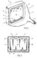
- FIG. 1 an exemplary color cathode ray tube (CRT) 11 having an envelope enclosure comprised of an integration of neck 13, funnel 15, and viewing panel 17 portions.
- CRT color cathode ray tube
- a multi-opening structure 21, such as an apertured shadow mask, is oriented within the viewing panel, in spatial relationship to the patterned screen, by a plurality of cooperating support means 23 and mating panel-embedded studs 25.
- an electron gun assembly 27 Encompassed within the forward region of the neck portion 13 is an electron gun assembly 27 from which electron beams are directed toward the screen 19.
- the multi-opening or mask-like member 21 in this instance being substantially rectangular, is comprised of a multi- apertured portion 29 attached to a perimetrical supporting frame 31.
- This framing member is formed of an integration of four framing elements, two of which are substantially horizontal elements 33 and 35 of substantially twelve and six o'clock orientations; and two substantially vertical elements 37 and 39 of substantially three and nine o'clock orientations.
- These integrated elements evidence a continuous rear-oriented instanding ledge 41 formed perimetrically thereabout. It is with this ledge that the improved shielding means of the invention are associated.
- the invention in its simplest form utilizes two substantially longitudinal open trough-like metallic shielding members of the type illustrated in Fig. 2 and denoted as 43.
- Each of these members is formed free of angular bends as a continuous one-piece structure of substantially arcuate cross-section, as shown in Fig. 3.
- the terminii of each member are advantageously formed as rounded closed ends 45 and 47.
- Such end shapings may be formed in an efficient stamping-shaping operation wherein some of the material is disposed as a multiplicity of minutely pressed strengthening folds or crimps, such as 49 and 51. These conform to the arcuate shaping and provide beneficial rigidity to the structure.
- each member the formation of suitable pedestal-like protuberances is effected as by shaped pressing during fabrication.
- two such pedestals 53 and 55 are formed in spaced relationship.
- Each of these pedestals evidences a seating area 57 and 59 for placement against a respective framing element, and apertures 58 and 60 may be fabricated in the respective seating areas for the accommodation of suitable attachment means to effect subsequent affixation to the supporting frame 31.
- the pressed formation of these respective protuberances produces additional crimps or folds of material adjacent thereto, such as 61 and 63 which further augment the rigidity of the shielding member.
- at least two arcuate strengthening ribs, such as 62 and 64 may be formed in the structure, preferably between the pedestals.
- a first shielding member 65 is seated against and affixed, by suitable means, in a horizontal position on the instanding ledge of the twelve o'clock framing element 33 of the supporting frame 31.
- the longitudinal opening of this first shielding member is oriented to face downward toward the six o'clock framing element 35.
- the second or cooperating shielding member 67 is seated on and affixed to the six o'clock framing element 35, with the shield opening facing upward toward the opposed first shielding member 65.
- shielding members 69 and 71 are seated on and suitably attached to the three and nine o'clock vertically oriented framing elements 37 and 39, as denoted in phantom in Fig. 5.
- a typical shielding member 43 is fabricated of, for example, 6 mil cold rolled steel material.
- the longitudinal dimension L of each such structure approximates the length dimension of the respective framing element to which it is subsequently attached.
- the L dimension is in the order of 9.66 inches (245.36 mm) and the depth D of the arcuate cross-section is in the order of 0.657 inches (16.b9 mm).
- the arcuate cross-sectional formation of the member is shown as being of substantially semi-circular shaping having a width W, the width may be flared somewhat as phantomed in Fig. 3 and denoted as W 2 .
- the exemplary width of the arcuate channel for a 13V CRT is in the order of being 1.046 inches (26.57 mm).
- the members comprising the improved shielding means of the invention may be expeditiously and inexpensively fabricated in a one draw forming and stamping operation in a manner to effect a ruggedized construction. Each shielding member is thus free of welds or constructional jointures and extra forming steps.
- the respective shielding members may be longitudinally formed to substantially conform therewith.
Landscapes
- Electrodes For Cathode-Ray Tubes (AREA)
- Vessels, Lead-In Wires, Accessory Apparatuses For Cathode-Ray Tubes (AREA)
Applications Claiming Priority (2)
| Application Number | Priority Date | Filing Date | Title |
|---|---|---|---|
| US06/475,266 US4517487A (en) | 1983-03-14 | 1983-03-14 | Cathode ray tube internal shielding means |
| US475266 | 1983-03-14 |
Publications (1)
| Publication Number | Publication Date |
|---|---|
| EP0118959A1 true EP0118959A1 (fr) | 1984-09-19 |
Family
ID=23886857
Family Applications (1)
| Application Number | Title | Priority Date | Filing Date |
|---|---|---|---|
| EP84200335A Ceased EP0118959A1 (fr) | 1983-03-14 | 1984-03-09 | Tube cathodique |
Country Status (4)
| Country | Link |
|---|---|
| US (1) | US4517487A (fr) |
| EP (1) | EP0118959A1 (fr) |
| JP (1) | JPS59177836A (fr) |
| CA (1) | CA1206509A (fr) |
Families Citing this family (3)
| Publication number | Priority date | Publication date | Assignee | Title |
|---|---|---|---|---|
| FR2555807B1 (fr) * | 1983-11-25 | 1986-04-11 | Videocolor | Masque d'ombre pour tube d'image en couleurs et tube d'image le comportant |
| JPS63231843A (ja) * | 1987-03-20 | 1988-09-27 | Hitachi Ltd | シヤドウマスク形カラ−受像管 |
| US5180947A (en) * | 1991-04-23 | 1993-01-19 | Alliant Techsystems Inc. | Shielded cathode ray tube |
Citations (3)
| Publication number | Priority date | Publication date | Assignee | Title |
|---|---|---|---|---|
| US4274031A (en) * | 1978-02-17 | 1981-06-16 | Nippon Electric Co., Ltd. | Color tube having shield correcting for terrestrial magnetism |
| EP0038516A1 (fr) * | 1980-04-17 | 1981-10-28 | Kabushiki Kaisha Toshiba | Tube d'image en couleur avec blindage magnétique intérieur |
| US4310779A (en) * | 1980-01-28 | 1982-01-12 | North American Philips Consumer Electronics Corporation | Cathode ray tube shield-funnel connective means |
Family Cites Families (3)
| Publication number | Priority date | Publication date | Assignee | Title |
|---|---|---|---|---|
| JPS5218165A (en) * | 1975-08-01 | 1977-02-10 | Hitachi Ltd | Production method of internal magnetic shield of color-image receiving tube |
| DE2549732A1 (de) * | 1975-11-06 | 1977-05-26 | Licentia Gmbh | Farbwahlmaskenanordnung fuer eine farbbildkathodenstrahlroehre |
| US4327307A (en) * | 1979-03-19 | 1982-04-27 | North American Philips Consumer Electronics Corp. | Shadow mask for color cathode ray tube |
-
1983
- 1983-03-14 US US06/475,266 patent/US4517487A/en not_active Expired - Fee Related
-
1984
- 1984-03-08 CA CA000449109A patent/CA1206509A/fr not_active Expired
- 1984-03-09 EP EP84200335A patent/EP0118959A1/fr not_active Ceased
- 1984-03-12 JP JP59046972A patent/JPS59177836A/ja active Pending
Patent Citations (3)
| Publication number | Priority date | Publication date | Assignee | Title |
|---|---|---|---|---|
| US4274031A (en) * | 1978-02-17 | 1981-06-16 | Nippon Electric Co., Ltd. | Color tube having shield correcting for terrestrial magnetism |
| US4310779A (en) * | 1980-01-28 | 1982-01-12 | North American Philips Consumer Electronics Corporation | Cathode ray tube shield-funnel connective means |
| EP0038516A1 (fr) * | 1980-04-17 | 1981-10-28 | Kabushiki Kaisha Toshiba | Tube d'image en couleur avec blindage magnétique intérieur |
Also Published As
| Publication number | Publication date |
|---|---|
| CA1206509A (fr) | 1986-06-24 |
| US4517487A (en) | 1985-05-14 |
| JPS59177836A (ja) | 1984-10-08 |
Similar Documents
| Publication | Publication Date | Title |
|---|---|---|
| US5534746A (en) | Color picture tube having shadow mask with improved aperture spacing | |
| US5644192A (en) | Color picture having a tensioned mask and compliant support frame assembly | |
| US4580076A (en) | Color cathode ray tube | |
| GB2136200A (en) | Cathode-ray tube shadow mask contour | |
| US3549932A (en) | Color television tube with shadow mask assembly provided with shield for reducing x-ray radiation and the effect of stray magnetic fields | |
| GB2136198A (en) | Cathode-ray tube faceplate panel | |
| TW346636B (en) | Color picture tube | |
| US4517487A (en) | Cathode ray tube internal shielding means | |
| US5434470A (en) | Colour display tube having an internal magnetic shield | |
| JP2588513B2 (ja) | カラ−陰極線管 | |
| JP2589611B2 (ja) | カラー映像管 | |
| US4310779A (en) | Cathode ray tube shield-funnel connective means | |
| JPH0660822A (ja) | 陰極線管 | |
| US4433267A (en) | CRT Internal contactor positioning means | |
| JPH06243794A (ja) | 陰極線管の内部磁気シールド | |
| US4280077A (en) | Cathode-ray tube having corrugated shadow mask with varying waveform | |
| CN1276652C (zh) | 安装在机箱内的阴极射线管 | |
| US4259611A (en) | Segmented shadow mask | |
| US3973162A (en) | Cathode support means for a CRT electron generating assembly | |
| US6731055B2 (en) | Color picture tube having a low expansion tension mask attached to a higher expansion frame | |
| EP0365686A1 (fr) | Tube d'affichage fluorescent | |
| US6873096B2 (en) | Mask support blade structure having an insert | |
| JP3452377B2 (ja) | 内部磁気シールドを有する陰極線管 | |
| JP3480977B2 (ja) | 内部磁気シールド及びそれを用いた陰極線管 | |
| JPH06338273A (ja) | 画像表示素子 |
Legal Events
| Date | Code | Title | Description |
|---|---|---|---|
| PUAI | Public reference made under article 153(3) epc to a published international application that has entered the european phase |
Free format text: ORIGINAL CODE: 0009012 |
|
| AK | Designated contracting states |
Designated state(s): DE FR GB |
|
| 17P | Request for examination filed |
Effective date: 19841220 |
|
| 17Q | First examination report despatched |
Effective date: 19860213 |
|
| D17Q | First examination report despatched (deleted) | ||
| STAA | Information on the status of an ep patent application or granted ep patent |
Free format text: STATUS: THE APPLICATION HAS BEEN REFUSED |
|
| 18R | Application refused |
Effective date: 19861031 |
|
| RIN1 | Information on inventor provided before grant (corrected) |
Inventor name: TAMBURRINO, RICHARD ANDREW |