EP0038547A2 - Schwingungsdämpfer für Kraftfahrzeug - Google Patents
Schwingungsdämpfer für Kraftfahrzeug Download PDFInfo
- Publication number
- EP0038547A2 EP0038547A2 EP81102974A EP81102974A EP0038547A2 EP 0038547 A2 EP0038547 A2 EP 0038547A2 EP 81102974 A EP81102974 A EP 81102974A EP 81102974 A EP81102974 A EP 81102974A EP 0038547 A2 EP0038547 A2 EP 0038547A2
- Authority
- EP
- European Patent Office
- Prior art keywords
- rubber member
- vibration absorber
- automotive vehicle
- set forth
- vibration
- Prior art date
- Legal status (The legal status is an assumption and is not a legal conclusion. Google has not performed a legal analysis and makes no representation as to the accuracy of the status listed.)
- Granted
Links
Images


Classifications
-
- F—MECHANICAL ENGINEERING; LIGHTING; HEATING; WEAPONS; BLASTING
- F16—ENGINEERING ELEMENTS AND UNITS; GENERAL MEASURES FOR PRODUCING AND MAINTAINING EFFECTIVE FUNCTIONING OF MACHINES OR INSTALLATIONS; THERMAL INSULATION IN GENERAL
- F16F—SPRINGS; SHOCK-ABSORBERS; MEANS FOR DAMPING VIBRATION
- F16F1/00—Springs
- F16F1/36—Springs made of rubber or other material having high internal friction, e.g. thermoplastic elastomers
- F16F1/373—Springs made of rubber or other material having high internal friction, e.g. thermoplastic elastomers characterised by having a particular shape
- F16F1/377—Springs made of rubber or other material having high internal friction, e.g. thermoplastic elastomers characterised by having a particular shape having holes or openings
-
- F—MECHANICAL ENGINEERING; LIGHTING; HEATING; WEAPONS; BLASTING
- F16—ENGINEERING ELEMENTS AND UNITS; GENERAL MEASURES FOR PRODUCING AND MAINTAINING EFFECTIVE FUNCTIONING OF MACHINES OR INSTALLATIONS; THERMAL INSULATION IN GENERAL
- F16F—SPRINGS; SHOCK-ABSORBERS; MEANS FOR DAMPING VIBRATION
- F16F1/00—Springs
- F16F1/36—Springs made of rubber or other material having high internal friction, e.g. thermoplastic elastomers
- F16F1/38—Springs made of rubber or other material having high internal friction, e.g. thermoplastic elastomers with a sleeve of elastic material between a rigid outer sleeve and a rigid inner sleeve or pin, i.e. bushing-type
- F16F1/387—Springs made of rubber or other material having high internal friction, e.g. thermoplastic elastomers with a sleeve of elastic material between a rigid outer sleeve and a rigid inner sleeve or pin, i.e. bushing-type comprising means for modifying the rigidity in particular directions
-
- F—MECHANICAL ENGINEERING; LIGHTING; HEATING; WEAPONS; BLASTING
- F16—ENGINEERING ELEMENTS AND UNITS; GENERAL MEASURES FOR PRODUCING AND MAINTAINING EFFECTIVE FUNCTIONING OF MACHINES OR INSTALLATIONS; THERMAL INSULATION IN GENERAL
- F16F—SPRINGS; SHOCK-ABSORBERS; MEANS FOR DAMPING VIBRATION
- F16F1/00—Springs
- F16F1/36—Springs made of rubber or other material having high internal friction, e.g. thermoplastic elastomers
- F16F1/42—Springs made of rubber or other material having high internal friction, e.g. thermoplastic elastomers characterised by the mode of stressing
- F16F1/52—Springs made of rubber or other material having high internal friction, e.g. thermoplastic elastomers characterised by the mode of stressing loaded in combined stresses
- F16F1/54—Springs made of rubber or other material having high internal friction, e.g. thermoplastic elastomers characterised by the mode of stressing loaded in combined stresses loaded in compression and shear
-
- F—MECHANICAL ENGINEERING; LIGHTING; HEATING; WEAPONS; BLASTING
- F16—ENGINEERING ELEMENTS AND UNITS; GENERAL MEASURES FOR PRODUCING AND MAINTAINING EFFECTIVE FUNCTIONING OF MACHINES OR INSTALLATIONS; THERMAL INSULATION IN GENERAL
- F16F—SPRINGS; SHOCK-ABSORBERS; MEANS FOR DAMPING VIBRATION
- F16F3/00—Spring units consisting of several springs, e.g. for obtaining a desired spring characteristic
- F16F3/08—Spring units consisting of several springs, e.g. for obtaining a desired spring characteristic with springs made of a material having high internal friction, e.g. rubber
- F16F3/087—Units comprising several springs made of plastics or the like material
-
- F—MECHANICAL ENGINEERING; LIGHTING; HEATING; WEAPONS; BLASTING
- F16—ENGINEERING ELEMENTS AND UNITS; GENERAL MEASURES FOR PRODUCING AND MAINTAINING EFFECTIVE FUNCTIONING OF MACHINES OR INSTALLATIONS; THERMAL INSULATION IN GENERAL
- F16F—SPRINGS; SHOCK-ABSORBERS; MEANS FOR DAMPING VIBRATION
- F16F2236/00—Mode of stressing of basic spring or damper elements or devices incorporating such elements
- F16F2236/12—Mode of stressing of basic spring or damper elements or devices incorporating such elements loaded in combined stresses
- F16F2236/123—Mode of stressing of basic spring or damper elements or devices incorporating such elements loaded in combined stresses loaded in compression and shear
Definitions
- the present invention relates to an improvement in the vibration absorber used for mounting a power unit (the engine and transmission together) in an automotive vehicle, and more specifically to the shapes of the rubber members used for the vibration absorber such that multistep vibration absorbing characteristics are provided, depending upon the shear and compression rates of deformation of the rubber member.
- vibration absorbers In order to absorb the vibration generated by the power unit of an automotive vehicle, there exist various vibration absorbers. In these prior-art vibration absorbers, usually two-step nonlinear vibration absorbing characteristics are required in order that the vibration is effectively damped by the shear deformation of the vibration absorbing rubber member when the vibration is relatively small and by the compression deformation thereof when the vibration is great. In this case however, since the vibration absorbing characteristics change abruptly, a sudden, unpleasant shock can be applied to the passengers.
- the vibration absorber according to the present invention comprises a novel rubber member provided with a plurality of appropriate size slots, cavities, or gaps at appropriate positions within the rubber member.
- the vibration absorber thus constructed has multistep vibration absorbing characteristics such that the rate of change of displacement of the rubber member is changed according to the load applied to the absorber, that is, the rubber member is deformed in dependence upon shear or upon compression deformation even within the compression region beyond the shear region.
- Fig. 1 shows a prior-art vibration absorber which includes a first member 1, a second member 2, and a rubber member 4.
- the first member 1 is formed of a metal plate roughly in a U-shape.
- the second member 2 is formed of the same metal plate roughly in the same U-shape, having a pair of vibration-receiving portions 3 in the direction from which vibration is applied, and is disposed between the first and second members with the rubber member 4 therebetween.
- the rubber member 4 is provided with a pair of clefts ⁇ 1 starting at the vibration-receiving portions 3 compression.
- Fig. 2 shows another prior-art vibration absorber which includes a first member lA, a second member 2A and rubber members 4A and 5A.
- the first member lA is formed roughly in a wide U-shape.
- the second member 2A is formed in a triangle shape, having a vibration-receiving portion 3A in the direction in which vibration is applied, and is disposed between the first and second members with the rubber member 4A therebetween.
- the rubber member 5A is disposed with a gap ⁇ 1 across from the vibration-receiving portion 3A.
- the first member lA is fixed to a vehicle body (not shown) by a studbolt 6A, and the second member 2 is fixed to a power unit (not shown) by another studbolt 7A.
- Fig. 4 in which is shown a first preferred embodiment of the present invention, indicating an improvement in the prior-art vibration absorber of Fig. 1.
- a second member 2 is connected to a U-shaped first member 1 by a rubber member 4 disposed therebetween in the middle of the first member 1.
- the rubber member 4 is provided with a pair of clefts ⁇ 2 starting at the pair of vibration-receiving portions 3 of the second member 2 along the inner surfaces of the first member 1, and serves as a stopper in the direction in which vibration is applied.
- a pair of elasticity change portions 9 consisting of dumbbell shaped slots composed of two holes 8 connected by a straight gap ô 3 is formed in order that the damping function of the rubber member 5 has two-step characteristics including shear elasticity and compression elasticity, as shown by the solid line b in Fig. 3.
- a triangle- shaped second member 2A is connected to a wide U-shaped .
- first member lA by a rubber member 4A disposed therebetween in the middle of the first member lA, with the apex 3A of the triangle directed toward the apex of another rubber member 5A to absorb vibration.
- a gap ⁇ 2 is provided between the rubber members 4A and 5A, to serve as a damper in the direction in which vibration is applied.
- an elasticity change portion 9A consisting of a dumbell shaped slot composed of two holes 8A connected by a straight gap ⁇ 3 is formed in order that the damping function of the rubber member 5A has two-step characteristics including shear elasticity and compression elasticity in the same way as in the embodiment shown in Fig. 4.
- the rubber member 5 or 5A which serves as a damper deforms under low elasticity in shear against the vibration applied in the ⁇ direction until the gap 8 or 8A is completely closed (within the range from P 1 to P 2 in Fig. 3). After that, the rubber member 5 or 5A deforms under high elasticity in compression (from P 2 in Fig. 3).
- the vibration absorber thus constructed is used to mount a power unit by connecting the first member 1 or lA to the vehicle body (not shown) by the studbolts 6 or 6A and the second member 2 or 2A to the power unit (not shown) by the other studbolt 7 or 7A, and when a large vibration is applied in the 0 direction in such a case as when the vehicle is suddenly accelerated or decelerated, the rubber member 4 or 4A between the first member 1 or lA and the second member 2 or 2A first deforms in shear and then deforms in compression depending upon the damping effect of the other rubber member 5 or 5A. Accordingly, it is possible to prevent the occurrence of a sudden shock by reducing the change of gradient of the elasticity characteristics.
- Fig. 6 shows a third preferred embodiment of the present invention.
- two-stage .elasticity characteristics are provided for the rubber member 5 or 5A
- a plurality of rubber projections with different projection height are formed in the rubber member 5A, and a gap 8A is provided in the largest rubber projection 5A 1 , so that a difference in projection' height is produced between the rubber-members SA l and 5A 2 even after the gap 8A has been closed.
- the elasticity characteristics have three-step characteristics as depicted by the dot-dot-dash line c in Fig.
- Fig. 7(A) and 7(B) show a fourth preferred embodiment where the first member is an outer cylindrical body 11 and the second member is an inner cylinder 12 and a pair of plate members 14 connected to the inner cylinder 12 by a shaft 17.
- the rubber member 13 is disposed between the outer cylindrical body 11 and the inner cylinder 12 with spaces between the sides of the rubber member 13 and the inner surfaces of the plate members 14.
- the rubber member 13 forms an elasticity change portion 16 on side projections 15a of the rubber member 13 placed between the outer and inner cylinders 11 and 12 and on other side projections 15b provided on the outer cylinder 11.
- the clearance between the rubber member 15a and the second member 14 is preset to ⁇ 2
- the clearance between the rubber member 15b and the second member 14 is preset to ⁇ 2 + ⁇ 3 for deformation in the axial direction of the shaft 17.
- this vibration absorber 13 When this vibration absorber 13 is used to mount a power unit by connecting the first member 11 to the power unit (not shown) and the second member 14 to the vehicle body (not shown) in the same way as in the previously described embodiments, it is possible to obtain two-step elasticity characteristics. That is to say, first the rubber member 13 deforms under shear due to vibration in the 0 direction because the outer cylinder 11 of the first member deforms toward the second member 14, next the rubber member 13 is brought into contact with the side of the second member 14 to produce a damping effect. In this case, first the a larger projection 15a of the rubber member 13 is brought into contact with the side of the second member 14 and deforms under shear along a gentle gradient corresponding to P 1 to P 2 in Fig. 3; next the smaller projection 15b of the rubber member 13 is brought into contact with the side of the second member 14 and deforms under shear along a sharp gradient corresponding to P 2 and after in Fig. 3'.
- Figs. 8(A) and 8(B) show a fifth embodiment in which the rubber member 13 providing a damping function includes a pair of flat rubber members 15c disposed on the , inner surfaces of a pair of second members 14 against the sides of an outer cylinder 11, and a rubber member 15d projecting from the sides of a rubber member 13 placed between an inner cylinder 12 and the outer cylinder 11.
- the clearance between the rubber member 15c and the rubber member 15d is preset to ⁇ 2 ; the clearance between the rubber member 15c and the outer cylinder 11 is preset to ⁇ 2 + ⁇ 3 .
- the relative displacement of the outer cylinder 11 of a first member from the second member 14 caused by vibration in the ⁇ direction produces a damping function when the rubber member 15d is brought into contact with the rubber member 15c attached to the second member 14, after the rubber member 13 disposed between the outer cylinder 11 and the inner cylinder 12 has been deformed under shear. That is to say, it is possible to obtain two-step elasticity characteristics such that first the rubber member 15d deforms under shear along a gentle gradient corresponding to P 1 to P 2 in Fig. 3; next the rubber member 15d is brought into contact with the rubber member 15c and deforms under compression along a sharp gradient corresponding to P 2 and after in Fig. 3.
- Figs. 9(A) and 9(B) show a sixth embodiment used for absorbing the vertical vibration of a power unit.
- a first member 20 is a octagonal cylinder fixed to the vehicle body 26 by a pair of brackets 21 provided on opposite sides thereof.
- a , second member 22 is a flat-shaped arm fixed to the power unit by another bracket 27 with the free end of the second member 22 being suspended at the center of the first member 20.
- a pair of rubber members 23 to absorb vibration in the ⁇ direction are provided on either the first member 20 or the second member 22 (on the inner wall of the first member 20 in this embodiment) facing the second member 22 and having an elasticity change portion 25 including a gap 24 within the rubber member 23.
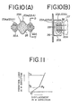
- Figs. 10(A) and 10(B) show a seventh embodiment.
- a pair of U-shaped second members 22A are placed within a first member 20A with their backs facing each other separated by an appropriate distance, and are connected by a rubber member 28 having two symmetrical large rubber projections 23A I at the middle thereof and four symmetrical small rubber projections 23A 2 near the pair of U-shaped members 22A, so that the rubber members 23A are provided with the elasticity change portion 25A due to shear.
- the vibration absorber for mounting a power unit since multistep elasticity characteristics are provided in dependence upon the shear and compression of the rubber member even while a medium frequency vibration is applied to the absorber, it is possible to realize the practical effect such that the vibration is appropriately and effectively damped, without producing shuddering, even while the vehicle is gradually accelerated or decelerated.
Landscapes
- Engineering & Computer Science (AREA)
- General Engineering & Computer Science (AREA)
- Mechanical Engineering (AREA)
- Health & Medical Sciences (AREA)
- Child & Adolescent Psychology (AREA)
- Vibration Prevention Devices (AREA)
- Springs (AREA)
- Arrangement Or Mounting Of Propulsion Units For Vehicles (AREA)
Applications Claiming Priority (2)
| Application Number | Priority Date | Filing Date | Title |
|---|---|---|---|
| JP52664/80 | 1980-04-21 | ||
| JP55052664A JPS602541B2 (ja) | 1980-04-21 | 1980-04-21 | 防振装置 |
Publications (3)
| Publication Number | Publication Date |
|---|---|
| EP0038547A2 true EP0038547A2 (de) | 1981-10-28 |
| EP0038547A3 EP0038547A3 (en) | 1982-05-26 |
| EP0038547B1 EP0038547B1 (de) | 1985-03-27 |
Family
ID=12921128
Family Applications (1)
| Application Number | Title | Priority Date | Filing Date |
|---|---|---|---|
| EP81102974A Expired EP0038547B1 (de) | 1980-04-21 | 1981-04-16 | Schwingungsdämpfer für Kraftfahrzeug |
Country Status (4)
| Country | Link |
|---|---|
| US (1) | US4392640A (de) |
| EP (1) | EP0038547B1 (de) |
| JP (1) | JPS602541B2 (de) |
| DE (1) | DE3169501D1 (de) |
Cited By (7)
| Publication number | Priority date | Publication date | Assignee | Title |
|---|---|---|---|---|
| EP0085188A1 (de) * | 1982-01-08 | 1983-08-10 | Nissan Motor Co., Ltd. | Isolierende Lagerung für einen Verbrennungsmotor oder dergleichen |
| FR2535261A1 (fr) * | 1982-10-27 | 1984-05-04 | Peugeot | Dispositif antibasculement pour groupe motopropulseur de vehicule automobile |
| EP0108000A1 (de) * | 1982-10-27 | 1984-05-09 | Automobiles Peugeot | Anti-Kippvorrichtung für Antriebsaggregat eines Kraftfahrzeuges |
| EP0268734A1 (de) * | 1986-10-28 | 1988-06-01 | WOCO Franz-Josef Wolf & Co. | Körperschallisolierendes weiches Lager |
| EP0302126A1 (de) * | 1987-08-03 | 1989-02-08 | WOCO Franz-Josef Wolf & Co. | Trockenlager |
| EP0335490A3 (de) * | 1988-03-29 | 1990-05-02 | Magnetic Peripherals Inc. | Plattenantriebseinheit |
| EP0449228A3 (en) * | 1990-03-27 | 1991-11-21 | Metzeler Gimetall Ag | Elastic engine mounting in wedged form |
Families Citing this family (30)
| Publication number | Priority date | Publication date | Assignee | Title |
|---|---|---|---|---|
| JPS57126794A (en) * | 1981-01-27 | 1982-08-06 | Sanshin Ind Co Ltd | Supporting structure for propulsion unit in outboard engine |
| JPS57200741A (en) * | 1981-06-03 | 1982-12-09 | Nissan Motor Co Ltd | Power unit mount body of car |
| JPS5997118U (ja) * | 1982-12-22 | 1984-07-02 | ダイハツ工業株式会社 | エンジンリヤマウンテイング装置 |
| JPS6014627A (ja) * | 1983-07-06 | 1985-01-25 | Nissan Motor Co Ltd | サスペンションメンバの筒状弾性ブッシュ |
| JPS60169441U (ja) * | 1984-04-19 | 1985-11-09 | トヨタ自動車株式会社 | 車両用クツシヨンゴム装置 |
| JPS6192329A (ja) * | 1984-10-11 | 1986-05-10 | Toyo Tire & Rubber Co Ltd | エンジン支持装置 |
| JPS61123225U (de) * | 1985-01-22 | 1986-08-02 | ||
| US4706946A (en) * | 1985-11-25 | 1987-11-17 | Thorn Richard P | Motion control strut |
| DE3609411C1 (de) * | 1986-03-20 | 1987-08-27 | Opel Adam Ag | Elastisches Lager zur Lagerung eines Antriebsaggregates in einem Kraftfahrzeug |
| JPS63112926U (de) * | 1987-01-16 | 1988-07-20 | ||
| DE3839914A1 (de) * | 1988-11-26 | 1990-05-31 | Freudenberg Carl Fa | Huelsengummifeder |
| US4964516A (en) * | 1989-09-18 | 1990-10-23 | Lord Corporation | Damped extended-motton strut |
| US5000428A (en) * | 1989-12-01 | 1991-03-19 | Lord Corporation | Fluid-damped strut |
| US5439203A (en) * | 1991-10-24 | 1995-08-08 | Toyoda Gosei Co., Ltd. | Vibration-damping bushing with sliding surface on insert located between inner and outer cylinders |
| JP3725346B2 (ja) * | 1998-09-02 | 2005-12-07 | 東洋ゴム工業株式会社 | 防振マウント |
| US6565061B1 (en) | 2000-09-28 | 2003-05-20 | Honeywell International Inc. | Radial snubber for vibration isolator |
| US7111705B2 (en) | 2004-02-02 | 2006-09-26 | Kurashiki Kako Co., Ltd. | Vibration isolating mount device |
| JP4617103B2 (ja) * | 2004-06-15 | 2011-01-19 | 倉敷化工株式会社 | 防振マウント装置 |
| US7568565B2 (en) * | 2004-08-17 | 2009-08-04 | Nes Technologies, Inc | Device, a system and a method for transferring vibrational energy |
| JP2006322552A (ja) * | 2005-05-19 | 2006-11-30 | Toyo Tire & Rubber Co Ltd | 防振装置 |
| JP2006329394A (ja) * | 2005-05-30 | 2006-12-07 | Toyo Tire & Rubber Co Ltd | 防振装置 |
| US7748689B2 (en) * | 2006-03-10 | 2010-07-06 | Paulstra Crc | Radially flexible bushing |
| US20070267259A1 (en) * | 2006-05-19 | 2007-11-22 | Textron Inc. | Rear suspension eyelet mount shock assembly |
| JP2009115136A (ja) * | 2007-11-02 | 2009-05-28 | Bridgestone Corp | 防振装置 |
| KR101184281B1 (ko) * | 2010-11-30 | 2012-09-21 | 기아자동차주식회사 | 차량용 롤로드 |
| CN103939521B (zh) * | 2014-04-29 | 2015-11-25 | 北京空间飞行器总体设计部 | 一种包含隔振器与非线性能量阱的被动混合减振装置及设计方法 |
| GB2537436B (en) * | 2015-09-10 | 2017-04-19 | Bentley Motors Ltd | Handling strut |
| GB201805838D0 (en) * | 2018-04-09 | 2018-05-23 | Dtr Vms Ltd | Bush |
| JP7218249B2 (ja) * | 2019-06-14 | 2023-02-06 | 株式会社プロスパイラ | 防振装置 |
| CN116872707A (zh) * | 2023-07-12 | 2023-10-13 | 奇瑞汽车股份有限公司 | 车辆悬置系统和车辆 |
Family Cites Families (12)
| Publication number | Priority date | Publication date | Assignee | Title |
|---|---|---|---|---|
| US1571713A (en) * | 1921-12-08 | 1926-02-02 | Elias J Emery | Buffer |
| FR1173461A (fr) | 1956-05-11 | 1959-02-25 | Daimler Benz Ag | Suspension d'essieu pour voitures automobiles |
| DE1430207A1 (de) | 1960-07-19 | 1968-12-12 | Opel Adam Ag | Lagerung des Antriebsaggregates eines Kraftfahrzeuges |
| FR1302704A (fr) | 1961-10-02 | 1962-08-31 | Gomma Antivibranti Applic | Butée anti-chocs, pour suspension de véhicules automobiles |
| FR1431821A (fr) | 1965-02-02 | 1966-03-18 | Commerciale Paulstra Soc | Perfectionnements apportés aux dispositifs de suspension des véhicules |
| DE6902616U (de) | 1969-01-24 | 1969-06-04 | Porsche F Kg | Elastisches lager, insbesondere elastisches keillager. |
| DE1931940A1 (de) | 1969-06-24 | 1971-02-11 | Lang Dr Georg | Elastisches Motorlager |
| DE2240157A1 (de) * | 1972-08-16 | 1974-02-28 | Metzeler Ag | Elastischer lagerkoerper |
| FR2262231A1 (en) | 1974-02-21 | 1975-09-19 | Paulstra Sa | Antivibration mounting for engines - different damping in each plane |
| FR2305646A1 (fr) | 1975-03-24 | 1976-10-22 | Peugeot & Renault | Support elastique, notamment pour moteur de vehicule |
| DE2703038C3 (de) * | 1977-01-26 | 1981-09-17 | Metzeler Kautschuk GmbH, 8000 München | Vorspannbares Lagerelement |
| DE7737712U1 (de) | 1977-12-10 | 1981-02-12 | Metzeler Kautschuk Gmbh, 8000 Muenchen | Vorspannbares Lagerelement |
-
1980
- 1980-04-21 JP JP55052664A patent/JPS602541B2/ja not_active Expired
-
1981
- 1981-04-13 US US06/253,570 patent/US4392640A/en not_active Expired - Lifetime
- 1981-04-16 EP EP81102974A patent/EP0038547B1/de not_active Expired
- 1981-04-16 DE DE8181102974T patent/DE3169501D1/de not_active Expired
Cited By (9)
| Publication number | Priority date | Publication date | Assignee | Title |
|---|---|---|---|---|
| EP0085188A1 (de) * | 1982-01-08 | 1983-08-10 | Nissan Motor Co., Ltd. | Isolierende Lagerung für einen Verbrennungsmotor oder dergleichen |
| US4568068A (en) * | 1982-01-08 | 1986-02-04 | Nissan Motor Company, Ltd. | Mounting insulator for internal combustion engine or the like |
| FR2535261A1 (fr) * | 1982-10-27 | 1984-05-04 | Peugeot | Dispositif antibasculement pour groupe motopropulseur de vehicule automobile |
| EP0108000A1 (de) * | 1982-10-27 | 1984-05-09 | Automobiles Peugeot | Anti-Kippvorrichtung für Antriebsaggregat eines Kraftfahrzeuges |
| US4632211A (en) * | 1982-10-27 | 1986-12-30 | Automobiles Peugeot | Anti-tilt device for a motor-drive unit of a motor vehicle |
| EP0268734A1 (de) * | 1986-10-28 | 1988-06-01 | WOCO Franz-Josef Wolf & Co. | Körperschallisolierendes weiches Lager |
| EP0302126A1 (de) * | 1987-08-03 | 1989-02-08 | WOCO Franz-Josef Wolf & Co. | Trockenlager |
| EP0335490A3 (de) * | 1988-03-29 | 1990-05-02 | Magnetic Peripherals Inc. | Plattenantriebseinheit |
| EP0449228A3 (en) * | 1990-03-27 | 1991-11-21 | Metzeler Gimetall Ag | Elastic engine mounting in wedged form |
Also Published As
| Publication number | Publication date |
|---|---|
| DE3169501D1 (en) | 1985-05-02 |
| EP0038547B1 (de) | 1985-03-27 |
| JPS56149216A (en) | 1981-11-19 |
| US4392640A (en) | 1983-07-12 |
| EP0038547A3 (en) | 1982-05-26 |
| JPS602541B2 (ja) | 1985-01-22 |
Similar Documents
| Publication | Publication Date | Title |
|---|---|---|
| EP0038547A2 (de) | Schwingungsdämpfer für Kraftfahrzeug | |
| EP0014742B1 (de) | Hydraulisch dämpfendes Einkammerlager | |
| US4566678A (en) | Polymeric apparatus and method of making the same | |
| DE68925650T2 (de) | Flüssigkeitsgefüllte Buchsenfeder mit einem beweglichen Glied in der Flüssigkeitskammer | |
| JPS6326441A (ja) | 粘性流体封入式ブツシユ | |
| US4200268A (en) | Shock-absorber | |
| CN112854506A (zh) | 结合碰撞阻尼的杆式调谐颗粒质量阻尼装置 | |
| EP0481144A1 (de) | Gedämpfte Strebe | |
| DE2816742A1 (de) | Elastisches lager | |
| US4796876A (en) | Engine mount | |
| US4546848A (en) | Differential gear housing supporting apparatus | |
| DE19929303A1 (de) | Luftdämpfer | |
| EP0268734A1 (de) | Körperschallisolierendes weiches Lager | |
| US4895355A (en) | Spring device for use in mounting apparatuses | |
| JPS5930006Y2 (ja) | 橋梁における制振装置 | |
| KR0142545B1 (ko) | 자동차 엔진의 롤 스톱퍼 마운팅 구조 | |
| DE3615070A1 (de) | Schwingungssystem | |
| JPS6145124A (ja) | 防振装置 | |
| EP0462510B1 (de) | Dämpfungseinheit, für Radaufhängungssystem in Kraftfahrzeugen | |
| EP0848183B1 (de) | Mehrkammer-Hydrauliklager | |
| DE8717411U1 (de) | Elastisches Lager, insbesondere Motorlager für Kraftfahrzeuge | |
| JPH04258549A (ja) | ダイナミックダンパ | |
| DE102015110612A1 (de) | Anordnung für ein Fahrzeugdach und System für ein Kraftfahrzeug | |
| SU1597460A1 (ru) | Рессорна подвеска измен емой жесткости | |
| SU934075A2 (ru) | Амортизатор |
Legal Events
| Date | Code | Title | Description |
|---|---|---|---|
| PUAI | Public reference made under article 153(3) epc to a published international application that has entered the european phase |
Free format text: ORIGINAL CODE: 0009012 |
|
| AK | Designated contracting states |
Designated state(s): DE FR GB |
|
| PUAL | Search report despatched |
Free format text: ORIGINAL CODE: 0009013 |
|
| AK | Designated contracting states |
Designated state(s): DE FR GB |
|
| 17P | Request for examination filed |
Effective date: 19820426 |
|
| GRAA | (expected) grant |
Free format text: ORIGINAL CODE: 0009210 |
|
| AK | Designated contracting states |
Designated state(s): DE FR GB |
|
| REF | Corresponds to: |
Ref document number: 3169501 Country of ref document: DE Date of ref document: 19850502 |
|
| ET | Fr: translation filed | ||
| RAP2 | Party data changed (patent owner data changed or rights of a patent transferred) |
Owner name: NISSAN MOTOR CO., LTD. |
|
| PLBE | No opposition filed within time limit |
Free format text: ORIGINAL CODE: 0009261 |
|
| STAA | Information on the status of an ep patent application or granted ep patent |
Free format text: STATUS: NO OPPOSITION FILED WITHIN TIME LIMIT |
|
| 26N | No opposition filed | ||
| PGFP | Annual fee paid to national office [announced via postgrant information from national office to epo] |
Ref country code: FR Payment date: 19910314 Year of fee payment: 11 |
|
| PG25 | Lapsed in a contracting state [announced via postgrant information from national office to epo] |
Ref country code: FR Effective date: 19921230 |
|
| REG | Reference to a national code |
Ref country code: FR Ref legal event code: ST |
|
| PGFP | Annual fee paid to national office [announced via postgrant information from national office to epo] |
Ref country code: GB Payment date: 19960409 Year of fee payment: 16 |
|
| PGFP | Annual fee paid to national office [announced via postgrant information from national office to epo] |
Ref country code: DE Payment date: 19960418 Year of fee payment: 16 |
|
| PG25 | Lapsed in a contracting state [announced via postgrant information from national office to epo] |
Ref country code: GB Effective date: 19970416 |
|
| GBPC | Gb: european patent ceased through non-payment of renewal fee |
Effective date: 19970416 |
|
| PG25 | Lapsed in a contracting state [announced via postgrant information from national office to epo] |
Ref country code: DE Free format text: LAPSE BECAUSE OF NON-PAYMENT OF DUE FEES Effective date: 19980101 |